ON Semiconductor RSL10 Getting Started
Hide thumbs
Also See for RSL10:
- Hardware reference manual (521 pages) ,
- Getting started (41 pages) ,
- Manual (37 pages)
Table of Contents
Advertisement
Quick Links
Download this manual
See also:
User Manual
Advertisement
Table of Contents

Related Manuals for ON Semiconductor RSL10


Summary of Contents for ON Semiconductor RSL10
- Page 1 Getting Started with RSL10 AND9697/D June 2019, Rev. P5 © SCILLC, 2019 Previous Edition © 2018 “All Rights Reserved”...
-
Page 2: Table Of Contents
......6 3. Getting Started with the Eclipse-Based ON Semiconductor IDE ....7 3.1 ON Semiconductor IDE and RSL10 CMSIS-Pack Installation Procedures . - Page 3 7. More Information ......41 7.1 Folder Structure of the RSL10 CMSIS-Pack Installation ....41 7.2 Documentation .
-
Page 4: Introduction
Bluetooth mesh networking CMSIS-Pack quickly enables mesh networking for any application. This document helps you to get started with the RSL10 SDK. It guides you through the process of connecting your RSL10 Evaluation and Development Board, installing an IDE and the CMSIS-Pack, configuring your environment, and building and debugging your first RSL10 application. -
Page 5: Setting Up The Hardware And Software
CHAPTER 2 Setting Up the Hardware and Software 2.1 Prerequisite Hardware The following items are needed before you can make connections: • RSL10 Evaluation and Development Board and a micro USB cable • A computer running Windows 2.2 C ONNECTING THE... -
Page 6: Preloaded Sample
“Peripheral Device with Sleep Mode” is on boards with a serial number lower than 1741xxxxx. • “Peripheral Device with Server” is on boards with a serial number higher than 1741xxxxx. For more information about sample applications, refer to the RSL10 Sample Code User’s Guide. 2.3 P REREQUISITE OFTWARE Install the latest version of J-Link. -
Page 7: Getting Started With The Eclipse-Based On Semiconductor Ide
EMICONDUCTOR NSTALLATION ROCEDURES If you have a previous version of the ON Semiconductor IDE (formerly known as the RSL10 Software Development Kit (SDK)) installed: Uninstall RSL10 Development Tools using Windows Control Panel. Check if the RSL10 SDK folder is still there; if it is, delete it. - Page 8 The RSL10 CMSIS-Pack now appears in the list of installed packs. In the Devices tab, if you expand All Devices > ONSemiconductor > RSL10 Series you can see RSL10 listed there. You can manage your installed packs in the Packs tab.
-
Page 9: Building Your First Sample Application With The On Semiconductor Ide
To use the IDE for the first time, follow the steps below: To start the IDE, go to the Windows Start menu, and select ON Semiconductor > ON Semiconductor IDE. When you open the IDE for the first time, you are prompted to select a workspace for the session. The workspace is the work area for all your IDE projects. - Page 10 Startup (libcmsis) components selected for blinky (see Figure 7 on page 11). NOTE: Sample projects are preconfigured with Release versions of RSL10 libraries, which are distributed as object files. In the RTE configuration, you can switch to the Source variant to include the source code of the library directly into your project (see Figure 7 on page 11).
-
Page 11: Build The Sample Code
ON Semiconductor Figure 7. RTE Configuration for the Blinky Example Project in the ON Semiconductor IDE 3.2.3 Build the Sample Code Follow these steps to build the sample code: Right click on the folder for blinky and click Build Project. Alternatively, you can select the project and click the hammer icon shown in Figure 8. - Page 12 Figure 8. Starting to Build a Project in the ON Semiconductor IDE When the build is running, the output of the build is shown in the ON Semiconductor IDE C/C++ Development Tooling (CDT) Build Console, as illustrated in Figure 9.
-
Page 13: Debugging The Sample Code
Figure 10. Output Files from Building a Sample Project NOTE: If the ON Semiconductor IDE has trouble finding the GNU toolchain, it might be caused by having other GNU toolchains installed. See Appendix B, “Arm Toolchain Support” on page 50 for more information. - Page 14 Development Board, see Section 6.4.1, “Downloading Firmware in Sleep Mode” on page 40. The ON Semiconductor IDE asks if you would like to open the Debug perspective. Answer Yes, and click on Remember my decision so that the question is not asked again.
-
Page 15: Peripheral Registers View With The On Semiconductor Ide
The ON Semiconductor IDE includes a peripheral register view plugin that enables you to visualize and modify all of the RSL10 registers during a debug session. It can be configured by setting the path to the SVD file in the Debug session. - Page 16 Now you can see all the RSL10 peripherals displayed. Select the peripheral that you need to monitor, and open the Memory window to show the RSL10 peripheral registers. The read only registers are highlighted in green. If you wish, you can drag your Memory window and place it side-by-side with your source code view (see Figure 15 on page 18).
- Page 17 ON Semiconductor Figure 14. Peripheral Registers View Perspective in Debug Session After Setting SVD Path Click on the Value tab of the GPIO register to change the (HIGH/LOW) state of GPIO6, as shown in Figure 15. You can observe that the LED (DIO6) on your board changes its state.
- Page 18 Getting Started with RSL10 Figure 15. Toggling RSL10 DIO Using the Peripheral Registers View www.onsemi.com...
-
Page 19: Getting Started With Keil
RSL10 Figure 17. Installing the The IDE prompts you to read and accept our license agreement, then installs the RSL10 CMSIS-Pack in the C:\Keil_v5 folder. After installation, use File > Refresh as shown in Figure 18 to update your pack proprieties. -
Page 20: Building Your First Sample Application With The Keil Uvision Ide
Figure 18. Refresh Pack after installation The RSL10 CMSIS-Pack now appears in the list of installed packs. In the Devices tab, if you expand All Devices > ONSemiconductor > RSL10 Series, you can see RSL10 listed there. You can manage your installed packs in the Packs tab. -
Page 21: Import The Sample Code
4.3.1 Import the Sample Code To import the sample code: In the Pack installer, click on the Examples tab to list all the example projects included in the RSL10 CMSIS-Pack. Choose the example project called blinky, and click the Copy button to import it into your workspace (see Figure 20 on page 21). -
Page 22: Build The Sample Code
Getting Started with RSL10 Figure 21. RTE Configuration for the Blinky Example Project in the Keil Vision IDE 4.3.2 Build the Sample Code Build the sample code as follows: Right click on Target 1 and choose Rebuild all target files. Alternatively, you can use the icon shown in the Figure 22. -
Page 23: Debugging The Sample Code
ON Semiconductor Figure 23. Example of Build Output The key resulting output in Project Explorer in the IDE includes: • blinky.hex: HEX file for loading into Flash memory ® • blinky.axf: Arm executable file, run from RAM, used for debugging •... - Page 24 Getting Started with RSL10 Figure 25. Debug Session in the Keil Vision IDE NOTE: Debug configurations are preconfigured for the sample applications in the IDE’s CMSIS-Pack. Flash downloading through the Download icon (Figure 26) or F8 is not supported for J-Link in the IDE at this point.
-
Page 25: Getting Started With Iar
2.3.27 Figure 28. Installing the RSL10 CMSIS-Pack for the IAR Embedded Workbench IDE The IDE prompts you to read and accept the license agreement, then installs the RSL10 CMSIS-Pack in the CMSIS-Pack root folder. After installation, click on the refresh icon with yellow arrows, which shows the text Reload Packs in the CMSIS Pack root folder when you hover over it with your cursor, in the Packs tab (as shown in Figure 29), to update your pack proprieties. -
Page 26: Building Your First Sample Application With The Iar Embedded Workbench
For more information about the sample applications, see the RSL10 Sample Code User’s Guide. 5.3.1 Import the Sample Code Import the sample code to your workspace as follows: In the IDE’s CMSIS Manager, click on the Examples tab to list all the example projects included in the RSL10 CMSIS-Pack. www.onsemi.com... - Page 27 Figure 31. IAR Embedded Workbench CMSIS Manager: Examples Tab Sample projects are preconfigured with Release versions of RSL10 libraries, which are distributed as object files. For the IDE, System library (libsyslib) and Startup (libcmsis) are preconfigured with the Source variant, so the source code of those libraries is included directly in both CMSIS Manager and IDE windows (see Figure 32 on page 27 and Figure 33 on page 28).
-
Page 28: Building The Sample Code
Getting Started with RSL10 Figure 33. RTE Configuration for the Blinky Example Project in the IAR Embedded Workbench window 5.3.2 Building the Sample Code To build the sample code: Right click on the folder for blinky and choose Rebuild all. Alternatively, you can use the icon shown in Figure 34. -
Page 29: Debugging The Sample Code
ON Semiconductor When the build is running, the output of the build is displayed in the Build Output view in the IDE, as illustrated in Figure 35. Figure 35. Example of Build Output The key resulting output shown in Project Explorer in the IDE includes: •... - Page 30 Getting Started with RSL10 Figure 37. J-link “Out of breakpoints” pop-up dialog If you are having trouble downloading firmware because an application with Sleep Mode is on the Evaluation and Development Board, see Section 6.4.1, “Downloading Firmware in Sleep Mode” on page 40.
- Page 31 ON Semiconductor Figure 38. Debug Session in the IAR Embedded Workbench www.onsemi.com...
-
Page 32: Advanced Debugging
Advanced Debugging 6.1 P RINTF EBUG APABILITIES macro is used to provide debug capability in RSL10 applications. The implementation PRINTF() printf() of the macro is user selectable to allow for different types of debug interfaces. The functionality is accessed PRINTF() via the tracing API. -
Page 33: Arm Cortex-M3 Core Breakpoints
ON Semiconductor set {int} &__VTOR = ISR_Vector_Table set $sp = *((int *) &ISR_Vector_Table) Figure 39. Setting Up a GDB Launch Configuration, Startup Tab 6.3 Arm Cortex-M3 Core Breakpoints A maximum of two hardware breakpoints can be set at a given time. If you need more than two breakpoints, you can use the Unlimited Flash Breakpoints feature available through J-Link. - Page 34 The following instructions show an example of how to perform this on the peripheral_server_sleep sample application in the ON Semiconductor IDE, but you can also adapt it for other applications that use sleep mode, and for other IDEs.
- Page 35 ON Semiconductor Figure 41. Setting Reset Type in the Debug Configuration Session Figure 42. Startup Tab: Debug Session that Initiates Restart www.onsemi.com...
- Page 36 Getting Started with RSL10 Debug session that connects to the running target: Create another new debug configuration under the GDB SEGGER heading, with new configuration details in the right panel. ii. Adjust the displayed values for your configuration then click on Apply (see Figure 43 and Figure 44 on page 37).
- Page 37 ON Semiconductor Figure 44. Startup Tab: Debug Session that Connects to the Running Target NOTE: If you are having trouble connecting to the running target, you can perform a software recovery by setting the Reset Type to 1 in the Debug session configuration as shown in Figure 44. The default Reset type is set to 0, which only resets the Arm Cortex-M3 core and leaves the device/ peripherals in a state where the J-Link cannot reconnect.
- Page 38 Getting Started with RSL10 Figure 45. First Debug Session Perspective Before Starting Execution Wait until the target enters Deep Sleep Mode. At this point the debug connection is lost; and even when the target is awake, it cannot establish a connection with JTAG. The following output is generated on the console (see Figure 46).
- Page 39 ON Semiconductor Figure 46. Debug Session Perspective when Debug Connection is Lost Stop the debug session and click on the Terminate icon to remove all terminated targets (see Figure 47). Figure 47. Terminate Targets Icon After the target exits Deep Sleep Mode, it is running in the infinite loop (step 1), and we can connect to the running target by starting the second debug session (see Figure 48).
-
Page 40: Downloading Firmware In Sleep Mode
Getting Started with RSL10 Figure 48. Second Debug Session Perspective After Connecting to the Running Target 6.4.1 Downloading Firmware in Sleep Mode If an application with Sleep Mode is currently on your board, and changing the Reset Type to 1 as described in Section 6.4, “Debugging with Low Power Sleep Mode”... -
Page 41: More Information
J-Link flash loader files. configuration Hardware, firmware and software documentation in PDF format. Also 3rd-party documentation documentation from other companies besides ON Semiconductor. Available from the books tab in the IDE. Contains evaluation board pictures. images Include files for the firmware components and libraries. Projects can point to this directory include and sub-directories when including firmware header files. - Page 42 Getting Started with RSL10 • ON Semiconductor IDE: documentation is accessible through the C/C++ perspective by opening any RTE configuration file, such as blinky.rteconfig, and selecting the tab Device (see Figure 49 on page 42). Keil Vision IDE: documentation is available in the Books tab, as shown in Figure 50 on page 43.
- Page 43 ON Semiconductor Figure 50. Accessing RSL10 Documentation from the Keil Vision IDE www.onsemi.com...
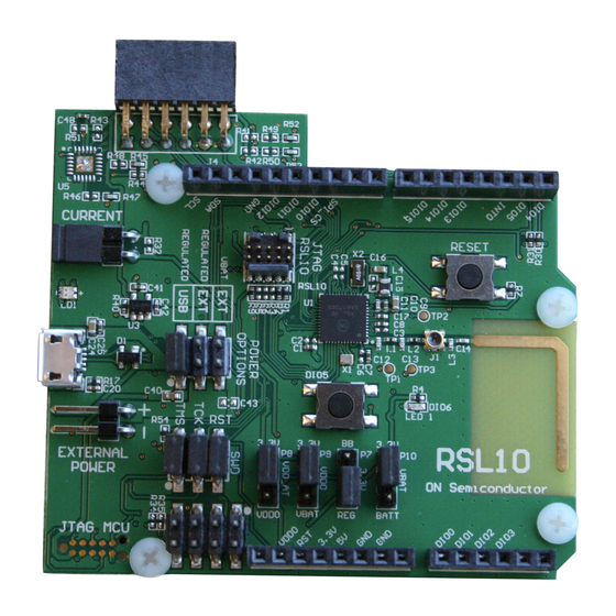
- Page 44 RSL10 Evaluation and Development Board. When you use this board with the software development tools, you can test and measure the performance and capabilities of the RSL10 radio SoC.
- Page 45 ON Semiconductor RSL10 Hardware Reference Describes all the functional features provided by the RSL10 SoC, including how these features are configured and how they can be used. This manual is a good place to start when you are designing real-time implementations of your algorithms. or planning a product based on the RSL10 SoC.
-
Page 46: Documentation In The Documentation.zip File
CMSIS-Pack as well as the following: Getting Started with RSL10 Bluetooth Low Energy Mesh Helps you to get started with the RSL10 mesh package. It guides you through the process of installing the mesh package alongside the RSL10 SDK, configuring your environment, and building and debugging your first RSL10 mesh network. - Page 47 Provides the information that you need to use the stand-alone flash loader. It describes the operations that the flash loader can perform, and explains how to configure the flash loader to connect to an RSL10 radio IC. The stand-alone flash loader is used to program, erase and read flash memory in RSL10.
-
Page 48: Migrating To Cmsis-Pack
If not, your project is not managed by CMSIS-Packs and needs to be migrated. The easiest way to migrate your existing Eclipse project to the new IDE is to start from one of the CMSIS-Pack RSL10 sample... -
Page 49: Using The Latest Rsl10 Firmware In A Previous Version Of The Eclipse-Based Ide
We recommend always updating your installation to the latest version of the Eclipse-based ON Semiconductor IDE. However, if your circumstances are such that this is impractical, you can manually update the RSL10 firmware files in a previous version of the Eclipse-based IDE. If this is your case, try the following steps: Download the RSL10 SDK CMSIS-Pack from www.onsemi.com/RSL10... -
Page 50: Arm Toolchain Support
When the user starts the ON Semiconductor IDE with the IDE.exe program (whose shortcut is located in Windows menu items), the arm_tools\bin directory is added to the path, to give the ON Semiconductor IDE access to the toolchain installed with the RSL10 software tools. - Page 51 LIMITATIONS OF LIABILITY: ON Semiconductor shall not be liable for any special, consequential, incidental, indirect or punitive damages, including, but not limited to the costs of requalification, delay, loss of profits or goodwill, arising out of or in connection with the board, even if ON Semiconductor is advised of the possibility of such damages. In no event shall ON Semiconductor’s aggregate liability from any obligation arising out of or in connection with the board, under any theory of liability, exceed the purchase price paid...
Need help?
Do you have a question about the RSL10 and is the answer not in the manual?
Questions and answers