Sign In
Upload
Manuals
Brands
OMRON Manuals
Temperature Controller
EJ1 EtherCAT
OMRON EJ1 EtherCAT Manuals
Manuals and User Guides for OMRON EJ1 EtherCAT. We have
8
OMRON EJ1 EtherCAT manuals available for free PDF download: User Manual, Quick Start Manual, Instruction Manual
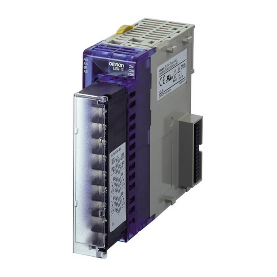
Omron EJ1 EtherCAT User Manual (324 pages)
Modular Temperature Controllers
Brand:
Omron
| Category:
Temperature Controller
| Size: 7 MB
Table of Contents
Table of Contents
21
Section 1 Outline
29
Outline
29
Appearance
30
Names of Parts
30
Names of Parts on Front Panel
30
Meanings of Indicators
31
Using Setting Switches
31
I/O Configuration
34
I/O Configuration and Main Functions
34
Main Unit Functions
35
Model Number Legend
36
Internal Block Diagrams
38
Section 2 Preparations
41
Preparations
41
Dimensions (Unit: MM)
42
Installation
42
Mounting and Removing Terminal Blocks
43
Terminal Arrangement
46
Wiring Terminals
46
Wiring Precautions
48
Wiring
49
Procedure
57
Using Tool Ports
57
Unit Configuration Examples
58
Connection Precautions
60
Section 3 Typical Control Examples
65
Typical Control Examples
65
Application
66
Minimum Configuration for Control
66
Setup
67
Wiring
67
Adjustment
69
Application
70
Multi-Channel Control
70
Setup
71
Wiring
71
Adjustment
72
Application
73
Control Linked to a Host Device
73
Wiring
74
Setup
75
Adjustment
76
Application
77
Controlling G3ZA Controllers Connected to Output Devices
77
Wiring
79
Adjustment
80
Setup
80
Section 4 Basic Units (Tc4 and Tc2) Functions
81
Basic Units (TC4 and TC2) Functions
81
Input Type
83
Setting Input Specifications
83
Analog Inputs
84
Temperature Inputs
84
Input Shift (Correction)
85
Input Filter
88
Control Output Assignments
89
Setting Output Specifications
89
Control Output Method
90
Minimum Output ON/OFF Width V1.2
90
Output on Scheduling Function
91
Output Scaling
93
Transfer Outputs
94
Setting Control Specifications
97
Starting and Stopping Control
97
Selecting the Control Method
98
Selecting the Output Mode
101
Setting the Set Point
104
Setting the SP Ramp
105
Remote SP
106
Setting the Manipulated Variable (MV)
109
Tuning
111
Disturbance Overshoot Adjustment Function
116
4-3-10 Operation During Errors
117
Alarm Types
119
Setting Alarm Specifications
119
Alarm Hysteresis
120
Alarm Value
120
Alarm Latch
121
Standby Sequence
121
Alarm Delay
122
Closed in Alarm or Open in Alarm
122
Alarm SP Selection
123
Channel Alarm Status
123
CT Assignment (TC2)
124
Detecting Current Errors
124
Heater Burnout Alarm (HB Alarm)
124
Heater Short Alarm (HS Alarm)
131
Heater Overcurrent Alarm (OC Alarm)
133
Loop Burnout Alarm (LBA)
135
Using the Loop Break Alarm (LBA)
135
Bank Function
137
Other Functions (TC4 and TC2)
137
Event Inputs (TC2)
138
Internal Buses (TC4 and TC2)
139
Using G3ZA Multi-Channel Power Controllers
141
Using the G3PW V1.1
145
Section 5 Advanced Unit (Hfu) Functions
149
Advanced Unit (HFU) Functions
149
Connectable Devices
150
Programless Communications
150
Checking Operation
151
Detailed Settings
165
Description of Operation
173
Operation Command Codes for Programless Communications
184
Bit-Specified Operation Commands
188
Programless Communications Errors
191
Connecting more than One HFU
192
Connecting more than One HFU V1.1
192
CS/CJ/NJ-Series Plcs
192
MELSEC-Q/Qna/Qnas-Series Plcs
195
HFU Communications Unit no
199
Auxiliary Output Allocations
201
HFU Internal Buses
201
Other HFU Functions
201
Section 6 Compoway/F Communications
205
Compoway/F Communications
205
Communications Settings
206
Communications Specifications
206
Other Communications Settings
207
Send Data Wait Time
207
Unit Number Setting
207
Frame Configuration
208
FINS-Mini Text
210
Number of Elements
210
PDU Structure
210
Variable Type and Address
210
Communications Data
211
List of FINS-Mini Command Services
211
Detailed Description of Services
212
Read from Variable Area
212
Write to Variable Area
213
Composite Read from Variable Area
214
Composite Write to Variable Area
215
Composite Registration Read
216
Composite Read Registration
217
Composite Read Registration Confirmation
218
Controller Attribute Read
219
Controller Status Read
220
6-4-10 Echoback Test
221
Operation Commands
222
Section 7 Modbus Communications V1.1
227
Modbus Communications
227
Communications Settings
228
Communications Specifications
228
Other Communications Settings
229
Send Data Wait Time
229
Unit Number Setting
229
Command Frames
230
Frames
230
Response Frames
231
Function Codes
232
Addresses
233
Communications Data
233
Number of Elements
233
Variable Areas
233
Detailed Description of Services
234
Multiple Read from Variable Area
234
Multiple Write to Variable Area
235
Single Write to Variable Area
236
Echoback Test
239
Section 8 Errors and Error Processing
241
Errors and Error Processing
241
Things to Check First
242
Determining Errors from Indicators
243
Determining the Error from the Status
245
Determining the Error from the Current Situation for Communications Errors
251
Determining the Error from the Current Situation for Temperature Measurement Errors
262
Determining the Error from the Current Situation for Temperature Control Errors
263
Determining the Error from the Current Situation for Output Errors
265
Determining the Error from the Current Situation for Heater Burnout Alarm Errors
266
Appendix
267
Ratings
268
Specifications
268
Characteristics
269
Current Transformer
271
Dimensions
271
Specifications
271
ASCII Table
272
Sensor Input Ranges
273
Parameter List
274
Status Lists
296
Parameters that Can be Allocated for Programless Communications
309
Index
313
Revision History
321
Advertisement
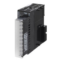
OMRON EJ1 EtherCAT User Manual (306 pages)
Modular Temperature Controllers
Brand:
OMRON
| Category:
Temperature Controller
| Size: 7 MB
Table of Contents
Table of Contents
20
Section 1 Outline
26
Outline
26
Names of Parts
27
Appearance
27
Names of Parts on Front Panel
27
Meanings of Indicators
28
Using Setting Switches
28
I/O Configuration and Main Functions
30
I/O Configuration
30
Main Unit Functions
31
Model Number Legend
32
Internal Block Diagrams
34
Preparations
36
Installation
37
Wiring Terminals
41
Using Tool Ports
51
Unit Configuration Examples
52
Section 3 Typical Control Examples
58
Typical Control Examples
58
Minimum Configuration for Control
59
Application
59
Wiring
60
Setup
60
Adjustment
62
Multi-Channel Control
63
Application
63
Wiring
64
Setup
64
Adjustment
65
Control Linked to a Host Device
66
Application
66
Wiring
67
Setup
68
Adjustment
69
Controlling G3ZA Controllers Connected to Output Devices
70
Application
70
Wiring
72
Setup
73
Adjustment
73
Section 4 Basic Units (Tc4 and Tc2) Functions
74
Basic Units (TC4 and TC2) Functions
74
Setting Input Specifications
76
Input Type
76
Temperature Inputs
77
Analog Inputs
77
Input Shift (Correction)
78
Input Filter
81
Setting Output Specifications
82
Control Output Assignments
82
Control Output Method
83
Minimum Output ON/OFF Width V1.2
83
Output on Scheduling Function
84
Output Scaling
86
Transfer Outputs
87
Setting Control Specifications
89
Starting and Stopping Control
89
Selecting the Control Method
90
Selecting the Output Mode
93
Setting the Set Point
96
Setting the SP Ramp
97
Remote SP
98
Setting the Manipulated Variable (MV)
101
Tuning
103
Disturbance Overshoot Adjustment Function
107
4-3-10 Operation During Errors
109
Setting Alarm Specifications
111
Alarm Types
111
Alarm Value
112
Alarm Hysteresis
112
Standby Sequence
113
Alarm Latch
113
Closed in Alarm or Open in Alarm
114
Alarm Delay
114
Alarm SP Selection
115
Channel Alarm Status
115
Detecting Current Errors
116
CT Assignment (TC2)
116
Heater Burnout Alarm (HB Alarm)
116
Heater Short Alarm (HS Alarm)
123
Heater Overcurrent Alarm (OC Alarm)
125
Using the Loop Break Alarm (LBA)
127
Loop Burnout Alarm (LBA)
127
Other Functions (TC4 and TC2)
129
Bank Function
129
Event Inputs (TC2)
130
Internal Buses (TC4 and TC2)
131
Using G3ZA Multi-Channel Power Controllers
133
Using the G3PW
136
Section 5 Advanced Unit (Hfu) Functions
140
Advanced Unit (HFU) Functions
140
Programless Communications
141
Connectable Devices
141
Checking Operation
142
Detailed Settings
154
Description of Operation
162
Operation Command Codes for Programless Communications
173
Bit-Specified Operation Commands
177
Programless Communications Errors
179
Connecting more than One HFU V1.1
180
SYSMAC CS/CJ-Series Plcs
180
MELSEC-Q/Qna/Qnas-Series Plcs
183
HFU Communications Unit no
187
Other HFU Functions
189
Auxiliary Output Allocations
189
HFU Internal Buses
189
Section 6 Compoway/F Communications
192
Compoway/F Communications
192
Communications Settings
193
Communications Specifications
193
Unit Number Setting
194
Other Communications Settings
194
Send Data Wait Time
194
Frame Configuration
195
FINS-Mini Text
197
PDU Structure
197
Variable Type and Address
197
Number of Elements
197
Communications Data
198
List of FINS-Mini Command Services
198
Detailed Description of Services
199
Read from Variable Area
199
Write to Variable Area
200
Composite Read from Variable Area
201
Composite Write to Variable Area
202
Composite Registration Read
203
Composite Read Registration
204
Composite Read Registration Confirmation
205
Controller Attribute Read
206
Controller Status Read
207
6-4-10 Echoback Test
208
Operation Commands
209
Section 7 Modbus Communications V1.1
214
Communications Settings
215
Communications Specifications
215
Unit Number Setting
216
Other Communications Settings
216
Send Data Wait Time
216
Frames
217
Command Frames
217
Response Frames
218
Function Codes
219
Variable Areas
220
Addresses
220
Number of Elements
220
Communications Data
220
Detailed Description of Services
221
Multiple Read from Variable Area
221
Multiple Write to Variable Area
222
Single Write to Variable Area
223
Echoback Test
226
Section 8 Errors and Error Processing
228
Errors and Error Processing
228
Things to Check First
229
Determining Errors from Indicators
230
Determining the Error from the Status
232
Determining the Error from the Current Situation for Communications Errors
237
Determining the Error from the Current Situation for Temperature Measurement Errors
246
Determining the Error from the Current Situation for Temperature Control Errors
247
Determining the Error from the Current Situation for Output Errors
249
Determining the Error from the Current Situation for Heater Burnout Alarm Errors
250
Appendix
252
Specifications
253
Ratings
253
Characteristics
254
Current Transformer
255
Specifications
255
Dimensions
255
ASCII Table
256
Sensor Input Ranges
257
Parameter List
258
Status Lists
280
Parameters that Can be Allocated for Programless Communications
293
Index
296
Revision History
304
Omron EJ1 EtherCAT User Manual (253 pages)
Modular Temperature Controller
Brand:
Omron
| Category:
Temperature Controller
| Size: 5 MB
Table of Contents
Table of Contents
18
Section 1
22
Outline
22
Names of Parts
23
Appearance
23
Names of Parts on Front Panel
23
Meanings of Indicators
23
Using Setting Switches
24
I/O Configuration and Main Functions
26
I/O Configuration
26
Main Unit Functions
27
Model Number Legend
28
Internal Block Diagrams
30
Section 2
32
Preparations
32
Installation
33
Wiring Terminals
37
Using Tool Ports
46
Unit Configuration Examples
47
Section 3
54
Typical Control Examples
54
Minimum Configuration for Control
55
Application
55
Wiring
56
Setup
56
Adjustment
58
Multi-Channel Control
59
Application
59
Wiring
60
Setup
60
Adjustment
61
Control Linked to a Host Device
62
Application
62
Wiring
63
Setup
64
Adjustment
65
Controlling G3ZA Controllers Connected to Output Devices
66
Application
66
Wiring
68
Setup
69
Adjustment
69
Section 4
70
Basic Units (TC4 and TC2) Functions
70
Setting Input Specifications
72
Input Type
72
Temperature Inputs
73
Analog Inputs
73
Input Shift (Correction)
74
Input Filter
77
Setting Output Specifications
78
Control Output Assignments
78
Control Output Method
78
Output on Scheduling Function
79
Output Scaling
81
Setting Control Specifications
83
Starting and Stopping Control
83
Selecting the Control Method
84
Selecting the Output Mode
87
Setting the Set Point
89
Setting the SP Ramp
90
Remote SP
91
Setting the Manipulated Variable (MV)
94
Tuning
96
Disturbance Overshoot Adjustment Function
99
4-3-10 Operation During Errors
100
Setting Alarm Specifications
102
Alarm Types
102
Alarm Value
103
Alarm Hysteresis
103
Standby Sequence
104
Alarm Latch
104
Closed in Alarm or Open in Alarm
105
Alarm Delay
105
Alarm SP Selection
106
Channel Alarm Status
106
Detecting Current Errors
107
CT Assignment (TC2)
107
Heater Burnout Alarm (HB Alarm)
107
Heater Short Alarm (HS Alarm)
114
Heater Overcurrent Alarm (OC Alarm)
116
Using the Loop Break Alarm (LBA)
118
Loop Burnout Alarm (LBA)
118
Other Functions (TC4 and TC2)
120
Bank Function
120
Event Inputs (TC2)
121
Internal Buses (TC4 and TC2)
122
Using G3ZA Multi-Channel Power Controllers
124
Section 5
128
Advanced Unit (HFU) Functions
128
Programless Communications
129
Connectable Devices
129
Checking Operation
130
Detailed Settings
138
Description of Operation
144
Operation Command Codes for Programless Communications
154
Programless Communications Errors
158
Other HFU Functions
159
Auxiliary Output Allocations
159
HFU Internal Buses
159
Section 6
162
Communications (Compoway/F)
162
Communications Settings
163
Communications Specifications
163
Unit Number Setting
164
Other Communications Settings
164
Send Data Wait Time
164
Frame Configuration
165
FINS-Mini Text
167
PDU Structure
167
Variable Type and Address
167
Number of Elements
167
Communications Data
168
List of FINS-Mini Command Services
168
Detailed Description of Services
169
Read from Variable Area
169
Write to Variable Area
170
Composite Read from Variable Area
171
Composite Write to Variable Area
172
Composite Registration Read
173
Composite Read Registration
174
Composite Read Registration Confirmation
175
Controller Attribute Read
176
Controller Status Read
177
6-4-10 Echoback Test
178
Operation Commands
179
Section 7
184
Errors and Error Processing
184
Things to Check First
185
Determining Errors from Indicators
186
Determining the Error from the Status
188
Determining the Error from the Current Situation for Communications Errors
193
Determining the Error from the Current Situation for Temperature Measurement Errors
202
Determining the Error from the Current Situation for Temperature Control Errors
203
Determining the Error from the Current Situation for Output Errors
205
Determining the Error from the Current Situation for Heater Burnout Alarm Errors
206
Appendix
208
Specifications
209
Ratings
209
Characteristics
210
Current Transformer
211
Specifications
211
Dimensions
211
ASCII Table
212
Sensor Input Ranges
213
Parameter List
214
Status Lists
230
Parameters that Can be Allocated for Programless Communications
242
Index
244
Revision History
252
Advertisement
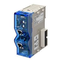
Omron EJ1 EtherCAT User Manual (124 pages)
Slave Unit
Brand:
Omron
| Category:
Control Unit
| Size: 4 MB
Table of Contents
Introduction
3
Terms and Conditions Agreement
4
Application Considerations
5
Disclaimers
5
Safety Precautions
6
Notation and Definitions for Precautionary Information
6
Symbols
6
Warnings and Cautions
7
Precautions for Safe Use
8
Precautions for Correct Use
11
Preparations for Use
12
Regulations and Standards
13
Revision History
14
Related Manuals
15
Ej1
15
G3PW Power Controllers
16
Meanings of Abbreviations and Terms
17
Contents
19
Sections in this Manual
19
Features and System Configuration
19
Table of Contents
20
Overview and Features
24
Overview
24
Features
24
System Configuration
25
Unit Models and Overview of Functions
27
Unit Model Number
27
Overview of Functions
27
Specifications and Procedures
29
Section 2 Specifications and Procedures
30
Specifications
30
General Specifications
30
Function Specifications
30
Ethercat Slave Communications Specifications
31
Application Procedures
32
Hardware Setup Procedure
32
Software Setup Procedure
33
Part Names and Functions
36
Appearance and Names of Parts on the Front Panel
36
Meanings of Indicators
37
Node Address Setting Switches
37
Ethercat Communications Connectors
38
Ethercat Communications Overview
39
Structure of CAN Application Protocol over Ethercat (Coe)
39
Ethercat Slave Information File (ESI Files)
40
State Transitions for Ethercat Communications
41
Process Data Objects (Pdos)
42
Service Data Objects (Sdos)
44
Installation and Connection
45
Installing the EJ1 Ethercat Slave Unit
46
Ethercat Network Wiring
47
Installation Precautions
47
Preparations for Installation
47
Recommended Ethercat Cables
48
Wiring the Temperature Controllers
49
Using the EJ1 Ethercat Slave Unit with PDO Communications
51
EJ1 PDO Communications Overview
52
How Data Is Sent and Received with PDO Communications
53
Compoway/F Commands and Responses
53
Control Commands and Responses
55
PDO Mapping Data Overview
56
Types of PDO Mapping Data
56
PDO Mapping Data List
57
PDO Mapping Data Details
58
Output Notification Data (Communications Master to EJ1 Ethercat Slave Unit)
58
Input Notification Data (EJ1 Ethercat Slave Unit to Communications Master)
60
Sysmac Error Status
64
Writing User Programming
65
Handshaking with the EJ1 Ethercat Slave Unit with User Programming
65
Handshaking with the EJ1 Ethercat Slave Unit with User Programming
66
Procedures for Sending Control Commands and Receiving Responses
67
Example Procedures for Sending Compoway/F Commands and Receiving Responses
68
Example of Sending and Receiving Data Without Dividing into Parts
68
Example Procedures for Sending Compoway/F Commands and Receiving
68
Responses
68
Example of Sending and Receiving Data in Parts
71
Setting Compoway/F Frames
75
Output Data and Input Data Contents
75
Storing Output Data and Input Data in Array Variables
77
Setting the PDO Mappings for I/O Data
78
Assigning Device Variables
82
Using the EJ1 Ethercat Slave Unit with SDO Communications
83
Section 6 Using the EJ1 Ethercat Slave Unit with SDO Communi-
84
Overview
84
Abort Codes
85
Troubleshooting
87
Section 7 Troubleshooting
88
Error Notification Methods
88
Error List
89
Errors Detected During Boot Process
89
Ethercat Communications Errors
90
Errors Detected During a Software Process
91
Error Notifications Based on the Sysmac Error Status
92
Sysmac Error Status
92
Checking and Responding to Event Codes
93
Error Notifications Provided with Emergency Messages
94
Emergency Messages
94
Error Notifications Based on the al Status
95
Maintenance and Inspection
97
Section 8 Maintenance and Inspection
98
Cleaning and Inspection
98
Cleaning
98
Inspection Methods
98
Inspection Items
99
Replacing Units
100
Unit Replacement Precautions
100
Unit Replacement Procedure
100
Appendices
101
A-1 Dimensions
102
A-1-1 Ej1N-Hfuc-Ect
102
Ej1N-Hfuc-Ect
102
A-2 Sample Programming
103
A-2-1 Items Common to All Programming Samples
103
Items Common to All Programming Samples
103
A-2-2 Sending Compoway/F Commands and Receiving Responses
106
A-2-3 Restart Port
108
A-3 Coe Objects
109
A-3-1 Object Dictionary Area
109
A-3-2 Data Type
109
Object Dictionary Area
109
Data Type
109
A-3-3 Communications Objects
110
A-3-4 PDO Mapping Objects
111
A-3-5 Sync Manager Communications Objects
114
Manufacturer-Specific Object 1
115
A-3-7 Device Profile Area
117
Index
117
Omron EJ1 EtherCAT User Manual (27 pages)
Modular Temperature Controller
Brand:
Omron
| Category:
Controller
| Size: 2 MB
Table of Contents
Unit Configuration Example
9
Nomenclature and Specification Settings
15
Basic Units
18
End Plate
19
Safety Precautions
20
Installation
21
Ordering Information
24
Specifications
24
Warranty and Application Considerations
26
Omron EJ1 EtherCAT Quick Start Manual (3 pages)
Modular Temperature Controller
Brand:
Omron
| Category:
Temperature Controller
| Size: 0 MB
Table of Contents
Accessories (Order Separately)
1
Specifications
1
Ratings
1
Options
2
Rail Mounting Equipment (Order Separately)
2
End Plate
2
Mounting to the DIN Rail
3
Mounting
3
Dismounting
3
Connecting to the G3ZA (EJ1N-TC)
3
Connecting to the G3PW (EJ1N-TC)
3
Omron EJ1 EtherCAT Instruction Manual (2 pages)
Brand:
Omron
| Category:
Temperature Controller
| Size: 1 MB
Table of Contents
Safety Precautions
1
Specifications
1
Wiring
1
Display
1
Names of Parts on Front Panel
1
Specification Settings
1
Switch Operation
1
Installation
1
Connections
1
Omron EJ1 EtherCAT Instruction Manual (2 pages)
Brand:
Omron
| Category:
Temperature Controller
| Size: 0 MB
Advertisement
Related Products
OMRON EJ1G
Omron EJ1G-TC2A-QNH
Omron EJ1G-TC2B-QNH
Omron EJ1G-TC4A-QQ
Omron EJ1G-TC4B-QQ
Omron EJ1G-HFUA-NFLK
Omron EJ1G-HFUB-NFLK
Omron EJ1G-HFUA-NFL2
Omron EJ1G-HFUB-NFL2
Omron EJ1C-EDUA-NFLK
OMRON Categories
Blood Pressure Monitor
Controller
Accessories
Switch
Inverter
More OMRON Manuals
Login
Sign In
OR
Sign in with Facebook
Sign in with Google
Upload manual
Upload from disk
Upload from URL