Sign In
Upload
Manuals
Brands
Nuvoton Manuals
Microcontrollers
NuMicro Family
Nuvoton NuMicro Family Manuals
Manuals and User Guides for Nuvoton NuMicro Family. We have
1
Nuvoton NuMicro Family manual available for free PDF download: Technical Reference Manual
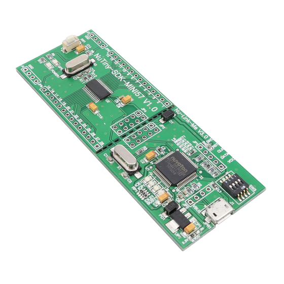
Nuvoton NuMicro Family Technical Reference Manual (475 pages)
Brand:
Nuvoton
| Category:
Microcontrollers
| Size: 5 MB
Table of Contents
Table of Contents
2
General Description
12
Features
13
Abbreviations
17
Table 3-1 List of Abbreviations
17
Parts Information List and Pin Configuration
18
Numicro Mini57 Naming Rule
18
Figure 4.1-1 Numicro Mini57 Series Selection Code
18
Numicro Mini57 Series Selection Guide
19
Table 4.2-1 Numicro Mini57 Series Selection Guide
19
Pin Configuration
20
TSSOP 28-Pin
20
Figure 4.3-1 Numicro ® Mini57 Series TSSOP 28-Pin Diagram
20
Figure 4.3-2 Numicro ® Mini57 Series TSSOP 28-Pin Multi-Function Diagram
20
TSSOP 20-Pin
21
Figure 4.3-3 Numicro ® Mini57 Series TSSOP 20-Pin Diagram
21
Figure 4.3-4 Numicro ® Mini57 Series TSSOP 20-Pin Multi-Function Diagram
21
QFN 33-Pin
22
Figure 4.3-5 Numicro ® Mini57 Series QFN 33-Pin Diagram
22
Figure 4.3-6 Numicro ® Mini57 Series QFN 33-Pin Multi-Function Diagram
23
Pin Description
24
Mini57 Series Pin Description
24
Table 4.4-1 TSSOP28 Pin Description
27
Table 4.4-2 TSSOP20 Pin Description
31
Table 4.4-3 QFN33 Pin Description
35
GPIO Multi-Function Pin Summary
36
Table 4.4-4 TSSOP20 Multi-Function Pin Summary
38
Block Diagram
39
Numicro Mini57 Block Diagram
39
Figure 5.1-1 Numicro Mini57 Block Diagram
39
Functional Description
40
ARM ® Cortex ® -M0 Core
40
Overview
40
Features
40
Figure 6.1-1 Functional Block Diagram
40
System Manager
42
Overview
42
System Reset
42
Figure 6.2-1 System Reset Resources
43
Table 6.2-1 Reset Value of Registers
44
Figure 6.2-2 Nreset Reset Waveform
45
Figure 6.2-3 Power-On Reset (POR) Waveform
45
Figure 6.2-4 Low Voltage Reset (LVR) Waveform
46
Figure 6.2-5 Brown-Out Detector (BOD) Waveform
47
Power Modes and Wake-Up Sources
48
Figure 6.2-6 Power Mode State Machine
48
Table 6.2-2 Power Mode Difference Table
48
Table 6.2-3 Clocks in Power Modes
49
Table 6.2-4 Condition of Entering Power-Down Mode Again
50
System Power Architecture
51
Mini57 Series Power Architecture Diagram
51
System Memory Mapping
52
Table 6.2-5 Memory Mapping Table
52
Register Protection
53
Table 6.2-6 Protected Registers
54
Memory Organization
55
Figure 6.2-8 Numicro Mini57 Flash, Security and Configuration Map
55
Table 6.2-7 Address Space Assignments for On-Chip Modules
56
Figure 6.2-9 SRAM Block Diagram
57
Register Map
58
Register Description
59
System Timer (Systick)
79
Nested Vectored Interrupt Control (NVIC)
84
Table 6.2-8 Exception Model
85
Table 6.2-9 System Interrupt Map Vector Table
86
Table 6.2-10 Vector Table Format
86
System Control Registers
104
Clock Controller
113
Overview
113
Figure 6.3-1 Clock Generator Block Diagram
113
Figure 6.3-2 Clock Generator Global View Diagram
114
Auto Trim
115
System Clock and Systick Clock
115
Figure 6.3-3 System Clock Block Diagram
115
Peripherals Clock Source Selection
116
Figure 6.3-4 Systick Clock Control Block Diagram
116
Figure 6.3-5 Peripherals Bus Clock Source Selection for PCLK
117
Power-Down Mode Clock
118
Frequency Divider Output
118
Table 6.3-1 Peripheral Clock Source Selection Table
118
Figure 6.3-6 Clock Source of Frequency Divider
119
Figure 6.3-7 Block Diagram of Frequency Divider
119
Register Map
120
Register Description
121
Table 6.3-2 Power-Down Mode Control Table
123
Flash Memory Controller (FMC)
133
Overview
133
Features
133
Block Diagram
133
Figure 6.4-1 Flash Memory Control Block Diagram
134
Functional Description
135
Table 6.4-1 Flash Memory Address Map
135
Figure 6.4-2 Flash Memory Organization
136
Table 6.4-2 Data Flash Table
136
Figure 6.4-3 Data Flash Shared with APROM
137
Figure 6.4-4 SPROM Security Mode
139
Figure 6.4-5 Boot Select (BS) for Power-On Action
144
Figure 6.4-6 Flash Memory Mapping of CBS in CONFIG0
145
Table 6.4-3 Boot Selection
145
Table 6.4-4 Boot Selection and Supports Function
145
Figure 6.4-7 Executable Range of Code with IAP Function Enabled
146
Figure 6.4-8 Example Flow of Boot Selection by BS Bit When CBS[0] = 1
147
Figure 6.4-9 ISP Flow Example
149
Table 6.4-5 ISP Command Table
149
Register Map
150
Register Description
151
General Purpose I/O (GPIO)
162
Overview
162
Features
162
Figure 6.5-1 I/O Pin Block Diagram
162
Block Diagram
163
Basic Configuration
163
Functional Description
163
Figure 6.5-2 GPIO Controller Block Diagram
163
Figure 6.5-3 Push-Pull Output
164
Figure 6.5-4 Open-Drain Output
165
Figure 6.5-5 Quasi-Bidirectional I/O Mode
165
GPIO Interrupt and Wake-Up Function
166
Register Map
167
Register Description
170
Timer Controller (TIMER)
187
Overview
187
Features
187
Block Diagram
188
Figure 6.6-1 Timer Controller Block Diagram
188
Figure 6.6-2 Clock Source of Timer Controller
188
Basic Configuration
189
Functional Description
189
Figure 6.6-3 Continuous Counting Mode
190
Figure 6.6-4 Free-Counting Capture Mode
191
Figure 6.6-5 External Reset Counter Mode
192
Table 6.6-1 Input Capture Mode Operation
193
Figure 6.6-6 Continuous Capture Mode Block
194
Figure 6.6-7 Continuous Capture Mode Behavior
195
Register Map
196
Register Description
197
Enhanced Input Capture Timer (ECAP)
209
Overview
209
Features
209
Block Diagram
209
Figure 6.7-1 Enhanced Input Capture Timer/Counter Architecture
209
Input Noise Filter
210
Figure 6.7-2 Enhanced Input Capture Timer/Counter Clock Source Control
210
Figure 6.7-3 Noise Filter Sampling Clock Selection
210
Figure 6.7-4 Noise Filter
210
Operation of Input Capture Timer/Counter
211
Figure 6.7-5 Enhanced Input Capture Timer/Counter Functions Block
212
Input Capture Timer/Counter Interrupt Architecture
213
Figure 6.7-6 Enhanced Input Capture Timer/Counter Interrupt Architecture Diagram
213
Register Map
214
Register Description
215
Enhanced PWM Generator (EPWM)
225
Overview
225
Features
225
Block Diagram
226
Figure 6.8-1 EPWM Clock Source
226
Figure 6.8-2 EPWM Block Diagram
227
Figure 6.8-3 EPWM Generator 0/1 Architecture Diagram
227
Figure 6.8-4 EPWM Generator 2/3 Architecture Diagram
227
Basic Configuration
228
Functional Description
228
Figure 6.8-5 EPWM Generator 4/5 Architecture Diagram
228
Figure 6.8-6 EPWM Edge-Aligned Waveform Output
229
Figure 6.8-7 EPWM Edge-Aligned Mode Operation Timing
230
Figure 6.8-8 EPWM Edge-Aligned Interrupt Diagram
231
Figure 6.8-9 EPWM Edge-Aligned Flow Diagram
232
Figure 6.8-10 EPWM Legend of Internal Comparator Output of PWM-Timer
233
Figure 6.8-11 EPWM-Timer Operation Timing
233
Figure 6.8-12 EPWM Center-Aligned Type
234
Figure 6.8-13 EPWM Center-Aligned Mode Operation Timing
235
Figure 6.8-14 EPWM Center-Aligned Waveform Output
236
Figure 6.8-15 EPWM Center-Aligned Interrupt Diagram
236
Figure 6.8-16 EPWM Center-Aligned Flow Diagram
237
Figure 6.8-17 EPWM Dead-Time Insertion
239
Figure 6.8-18 EPWM Asymmetric Mode Timing Diagram
240
Figure 6.8-19 EPWM One-Shot Mode Architecture
240
Figure 6.8-20 EPWM Initial State and Polarity Control with Rising Edge Dead-Time Insertion
241
Figure 6.8-21 EPWM Interrupt Architecture
242
Figure 6.8-22 EPWM Brake Architecture
243
Figure 6.8-23 EPWM 3-Phase Motor Mask Diagram
244
Figure 6.8-24 EPWM 3-Phase Motor Mask Example 1
245
Figure 6.8-25 EPWM 3-Phase Motor Mask Example 2
245
Register Map
247
Register Description
248
Basic PWM Generator (BPWM)
275
Overview
275
Features
275
Block Diagram
275
PWM-Timer Operation
276
Figure 6.9-1 PWM Clock Source Control
276
Figure 6.9-2 PWM Architecture Diagram
276
Figure 6.9-3 Legend of Internal Comparator Output of PWM-Timer
277
Figure 6.9-4 PWM-Timer Operation Timing
278
Figure 6.9-5 PWM Edge-Aligned Interrupt Generate Timing Waveform
278
Figure 6.9-6 Center-Aligned Type Output Waveform
279
Figure 6.9-7 PWM Center-Aligned Interrupt Generate Timing Waveform
280
Figure 6.9-8 PWM Double Buffering Illustration
281
Figure 6.9-9 PWM Controller Output Duty Ratio
281
Figure 6.9-10 Paired-PWM Output with Dead-Zone Generation Operation
282
Figure 6.9-11 PWM Interrupt Architecture Diagram
282
Register Map
284
Register Description
285
Watchdog Timer (WDT)
295
Overview
295
Features
295
Block Diagram
295
Figure 6.10-1 Watchdog Timer Block Diagram
295
Clock Control
296
Basic Configuration
296
Functional Description
296
Figure 6.10-2 Watchdog Timer Clock Control Diagram
296
Figure 6.10-3 Watchdog Timer Time-Out Interval and Reset Period Timing
297
Table 6.10-1 Watchdog Timer Time-Out Interval Period Selection
297
Registers Map
298
Register Description
299
USCI - Universal Serial Control Interface Controller
301
Overview
301
Features
301
Block Diagram
301
Figure 6.11-1 USCI Block Diagram
301
Functional Description
302
Table 6.11-1 Input Signals for Different Protocols
302
Figure 6.11-2 Input Conditioning for Uscix_Dat[1:0] and Uscix_Ctl[1:0]
303
Figure 6.11-3 Input Conditioning for Uscix_Clk
303
Table 6.11-2 Output Signals for Different Protocols
304
Figure 6.11-4 Block Diagram of Data Buffering
305
Figure 6.11-5 Data Access Structure
305
Figure 6.11-6 Transmit Data Path
306
Figure 6.11-7 Receive Data Path
307
Figure 6.11-8 Protocol-Relative Clock Generator
308
Figure 6.11-9 Basic Clock Divider Counter
309
Figure 6.11-10 Block of Timing Measurement Counter
309
Figure 6.11-11 Sample Time Counter
310
Figure 6.11-12 Event and Interrupt Structure
311
Table 6.11-3 Data Transfer Events and Interrupt Handling
311
Table 6.11-4 Protocol-Specific Events and Interrupt Handling
312
USCI - UART Mode
313
Overview
313
Features
313
Block Diagram
313
Figure 6.12-1 USCI - UART Mode Block Diagram
313
Basic Configuration
314
Functional Description
314
Figure 6.12-2 UART Signal Connection for Full-Duplex Communication
314
Table 6.12-1 Input Signals for UART Protocols
315
Table 6.12-2 Output Signals for Different Protocols
315
Figure 6.12-3 UART Standard Frame Format
316
Figure 6.12-4 UART Bit Timing (Data Sample Time)
318
Table 6.12-3 Baud Rate Relationship
319
Figure 6.12-5 UART Auto Baud Rate Control
320
Figure 6.12-6 Incoming Data Wake-Up
321
Register Map
324
Register Description
325
USCI - SPI Mode
346
Overview
346
Features
346
Figure 6.13-1 SPI Master Mode Application Block Diagram (X=0, 1)
346
Figure 6.13-2 SPI Slave Mode Application Block Diagram (X=0, 1)
346
Block Diagram
347
Basic Configuration
347
Figure 6.13-3 USCI - SPI Mode Block Diagram
347
Functional Description
348
Figure 6.13-4 4-Wire Full-Duplex SPI Communication Signals (Master Mode)
348
Table 6.13-1 SPI Communication Signals (X=0, 1)
348
Figure 6.13-5 4-Wire Full-Duplex SPI Communication Signals (Slave Mode)
349
Table 6.13-2 Serial Bus Clock Configuration
349
Figure 6.13-6 SPI Communication with Different SPI Clock Configuration (Sclkmode=0X0)
350
Figure 6.13-7 SPI Communication with Different SPI Clock Configuration (Sclkmode=0X1)
350
Figure 6.13-8 SPI Communication with Different SPI Clock Configuration (Sclkmode=0X2)
351
Figure 6.13-9 SPI Communication with Different SPI Clock Configuration (Sclkmode=0X3)
351
Figure 6.13-10 16-Bit Data Length in One Word Transaction with MSB First Format
352
Figure 6.13-11 Word Suspend Interval between Two Transaction Words
353
Figure 6.13-12 Auto Slave Select (SUSPITV ≧ 0X3)
354
Figure 6.13-13 Auto Slave Select (SUSPITV < 0X3)
354
Figure 6.13-14 SPI Timing in Master Mode
357
Figure 6.13-15 SPI Timing in Master Mode (Alternate Phase of Serial Bus Clock)
357
Figure 6.13-16 SPI Timing in Slave Mode
358
Figure 6.13-17 SPI Timing in Slave Mode (Alternate Phase of Serial Bus Clock)
358
Register Map
361
Register Description
362
USCI - I C Mode
384
Overview
384
Features
384
Figure 6.14-1 I 2 C Bus Timing
384
Block Diagram
385
Basic Configuration
385
Functional Description
385
Figure 6.14-2 USCI - I²C Mode Block Diagram
385
Figure 6.14-3 I 2 C Protocol
386
Figure 6.14-4 START and STOP Conditions
386
Figure 6.14-5 Bit Transfer on I C Bus
388
Figure 6.14-6 Acknowledge on I C Bus
388
Figure 6.14-7 Arbitration Lost
390
Figure 6.14-8 Control I
392
Status
392
Figure 6.14-9 Master Transmits Data to Slave with a 7-Bit Address
393
Figure 6.14-10 Master Reads Data from Slave with a 7-Bit Address
393
Figure 6.14-11 Master Transmits Data to Slave by 10-Bit Address
393
Figure 6.14-12 Master Reads Data from Slave by 10-Bit Address
394
Figure 6.14-13 Master Transmitter Mode Control Flow with 7-Bit Address
394
Figure 6.14-14 Master Receiver Mode Control Flow with 7-Bit Address
395
Figure 6.14-15 Save Mode Control Flow with 7-Bit Address
396
Figure 6.14-16 GC Mode with 7-Bit Address
398
Figure 6.14-17 Setup Time Wrong Adjustment
399
Table 6.14-1 Relationship between I
399
Baud Rate and PCLK
399
Figure 6.14-18 Hold Time Wrong Adjustment
400
Figure 6.14-19 I 2 C Time-Out Count Block Diagram
400
Figure 6.14-20 EEPROM Random Read
401
Figure 6.14-21 Protocol of EEPROM Random Read
402
Register Map
403
Register Description
404
Hardware Divider (HDIV)
422
Overview
422
Features
422
Basic Configuration
422
Functional Description
423
Figure 6.15-1 Hardware Divider Operation Flow
423
Register Map
424
Register Description
425
Analog to Digital Converter (ADC)
430
Overview
430
Features
430
Block Diagram
430
Figure 6.16-1 ADC Control Block Diagram
430
Basic Configuration
431
Functional Description
431
Figure 6.16-2 ADC Peripheral Clock Control
431
Figure 6.16-3 Single Mode Conversion Timing Diagram
432
Figure 6.16-4 ADC Hardware Trigger Source
433
Figure 6.16-5 Independent Sample Mode Conversion Timing Diagram
433
Figure 6.16-6 Simultaneous Simple Mode Conversion Timing Diagram
434
Figure 6.16-7 Simultaneous Sequential 4R Mode Conversion Timing Diagram
434
Register Map
435
Register Description
436
Analog Comparator (ACMP)
452
Overview
452
Features
452
Block Diagram
453
Basic Configuration
453
Figure 6.17-1 Analog Comparator Block Diagram
453
Functional Description
454
Figure 6.17-2 Analog Comparator Controller Interrupt Sources
454
Figure 6.17-3 Comparator Hysteresis Function
454
Comparator Reference Voltage (CRV)
455
Figure 6.17-4 Comparator Reference Voltage Block Diagram
455
Register Map
456
Register Description
457
Programmable Gain Amplifier
467
Overview
467
Features
467
Block Diagram
467
Register Map
467
Figure 6.18-1 OP Amplifier Block Diagram
467
Register Description
468
Application Circuit
469
Electrical Characteristics
470
Package Dimensions
471
28-Pin TSSOP (4.4X9.7X1.0 MM)
471
20-Pin TSSOP (4.4X6.5X0.9 MM)
472
33-Pin QFN33 (4X4X0.8 MM)
473
Revision History
474
Advertisement
Advertisement
Related Products
Nuvoton NuMicro series
Nuvoton NuMicro Nu-Link-Gang
Nuvoton NuMicro ISP
Nuvoton NuMicro NUC472 Series
Nuvoton NuMaker-M031TC
Nuvoton NuMicro NuMaker-IoT-M263A
Nuvoton NuMicro NuMaker-M032KG
Nuvoton NuMicro NuMaker-M483KG
Nuvoton NuMaker-M252KG
Nuvoton NuMicro NuMaker-M031TB
Nuvoton Categories
Motherboard
Microcontrollers
Computer Hardware
Amplifier
Control Unit
More Nuvoton Manuals
Login
Sign In
OR
Sign in with Facebook
Sign in with Google
Upload manual
Upload from disk
Upload from URL