Sign In
Upload
Manuals
Brands
Nord Drivesystems Manuals
Inverter
SK280E-FDS
Nord Drivesystems SK280E-FDS Manuals
Manuals and User Guides for Nord Drivesystems SK280E-FDS. We have
2
Nord Drivesystems SK280E-FDS manuals available for free PDF download: User Manual, Supplementary Manual
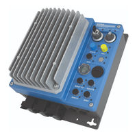
Nord Drivesystems SK280E-FDS User Manual (212 pages)
Brand:
Nord Drivesystems
| Category:
DC Drives
| Size: 3 MB
Table of Contents
Table 1: Version List BU0250
3
Table of Contents
5
1 General
9
Overview
10
Delivery
11
Table 2: Additional Features
11
Scope of Delivery
12
Safety, Installation and Application Information
14
Warning and Hazard Information
18
Warning and Hazard Information on the Product
18
Table 3: Warning and Hazard Information on the Product
18
Warning and Hazard Information in the Document
19
Standards and Approvals
19
Table 4: Standards and Approvals
19
UL and CSA Approval
20
Type Code / Nomenclature
23
Type Plate
23
Field Distribution Type Codes
25
Power Rating / Motor Size
26
Version with Protection Class IP55 / IP65
26
2 Assembly and Installation
27
Installation
27
Option Slots and Equipment Versions
29
Option Slots
29
Connection Level
29
Control Level
30
Maintenance Switch Level
30
Configuration Variants
31
Configurable Options
31
Configuration of Option Slots of the Control Level
32
Configuration of Option Slots on the Connection Level
35
Configuration of the Option Slot for the Maintenance Switch Level
39
Electrical Connection
40
Wiring Guidelines
41
Electrical Connection of Power Unit
42
Mains Connection
42
Motor Cable
43
Brake Resistor (B+, B-, PE)
44
Electromechanical Brake
45
Electrical Connection of the Control Unit
46
Control Connection Details
48
Basic Control Unit Configuration
50
Colour and Contact Assignments for the Incremental Encoder (HTL)
51
3 Display, Operation and Options
52
Displays
52
Control and Parametrisation Options
56
Control and Parameterisation Units, Use
56
Figure 1: Simplebox, Handheld, SK CSX-3H
56
Figure 2: Parameterbox, Handheld, SK PAR-3H
56
Connection of Multiple Devices to One Parametrisation Tool
57
Optional Modules
58
Cu4
58
Optional Plug-In EEPROM
59
4 Commissioning
62
Starting up the Device
62
Factory Settings
63
Selecting the Operating Mode for Motor Control
64
Explanation of the Operating Modes (P300)
64
Overview of Control Parameter Settings
66
Motor Control Commissioning Steps
67
Temperature Sensors
67
AS Interface (AS-I)
68
The Bus System
68
Features and Technical Data
70
Bus Structure and Topology
71
Commissioning
73
Connection
73
Displays
73
Configuration
74
Addressing
75
Certificate
76
5 Parameter
77
Parameter Overview
80
Description of Parameters
83
Operating Displays
84
Basic Parameters
86
Motor Data / Characteristic Curve Parameters
93
Speed Control
101
Control Terminals
110
Additional Parameters
131
Figure 3: SK CU4
144
Positioning
151
Information
151
6 Operating Status Messages
164
Display of Messages
165
Diagnostic Leds on Device
165
Messages
166
FAQ Operational Problems
174
Table 5: FAQ Operational Problems
175
7 Technical Data
176
General Data for Frequency Inverter
176
Technical Data for Determining the Energy Efficiency Level
177
Electrical Data
178
Electrical Data 3~400 V
178
8 Additional Information
180
Setpoint Processing
180
Figure 4 Setpoint Processing
180
Process Controller
181
Figure 5: Process Controller Flow Diagram
181
Process Controller Application Example
182
Process Controller Parameter Settings
183
Electromagnetic Compatibility (EMC)
184
General Provisions
184
EMC Evaluation
185
Table 6: EMC Comparison between en 61800-3 and en 55011
185
EMC of Device
186
Table 7: Overview According to Product Standard en 61800-3
187
EU Declaration of Conformity
188
Reduced Output Power
189
Increased Heat Dissipation Due to Pulse Frequency
189
Figure 6: Heat Losses Due to Pulse Frequency
189
Reduced Overcurrent Due to Time
190
Table 8: Overcurrent Relative to Time
190
Reduced Overcurrent Due to Output Frequency
191
Table 9: Overcurrent Relative to Pulse and Output Frequency
191
Reduced Output Current Due to Low Voltage
192
Reduced Output Current Due to the Heat Sink Temperature
192
Figure 7: Reduced Output Current Due to Low Voltage
192
Operation on the FI Circuit Breaker
193
System Bus
193
Energy Efficiency
195
Figure 8: Energy Efficiency Due to Automatic Flux Optimisation
195
Standardisation of Setpoint / Target Values
196
Definition of Setpoint and Actual Value Processing (Frequencies)
197
Table 10: Processing of Setpoints and Actual Values in the Frequency Inverter
197
Connection Accessories
198
Power Connections - Mating Connectors
198
M12 y Distributor
199
Motor Cable
200
Low Voltage Cable
200
Daisy Chain Cable
200
Encoder Cables
201
9 Maintenance and Servicing Information
202
Maintenance Instructions
202
Service Notes
203
Abbreviations
204
Advertisement
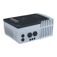
Nord Drivesystems SK280E-FDS Supplementary Manual (84 pages)
POSICON positioning control
Brand:
Nord Drivesystems
| Category:
Inverter
| Size: 1 MB
Table of Contents
Table of Contents
4
1 Introduction
8
General
8
Documentation
8
Document History
8
Copyright Notice
8
Publisher
9
About this Manual
9
Other Applicable Documents
9
Presentation Conventions
10
Warning Information
10
Other Information
10
2 Safety
11
Intended Use
11
Selection and Qualification of Personnel
11
Qualified Personnel
11
Qualified Electrician
11
Safety Information
12
3 Electrical Connection
13
Connection to SK 200E
13
Control Terminal Details
14
Connection to SK 250E-FDS
17
Control Level
17
Control Connection Details
21
Encoders
22
Canopen Absolute Encoders
22
Approved Canopen Absolute Encoders (with Bus Cover)
22
Contact Assignment for Canopen Encoders (SK 200E
22
Contact Assignment for Canopen Encoders (SK 250E-FDS
22
Table 1: Canopen Encoders Approved by NORD
22
Colour and Contact Assignments for the Incremental Encoder (HTL)
23
Colour and Contact Assignments for the Incremental Encoder (HTL)
24
4 Function Description
25
Introduction
25
Position Detection
25
Position Detection with Incremental Encoders
25
Approach Reference Point
26
Residual Position
27
Position Detection with Absolute Encoders
28
Supplementary Settings - Canopen Absolute Encoders
28
Table 2: Canopen Encoder Cycle Time Dependent on the Baud Rate
29
Referencing an Absolute Encoder
30
Manual Commissioning of the Canopen Absolute Encoder
30
Encoder Monitoring
31
Linear or Optimised Path Positioning Method
32
Table 3: Parameter P604 Encoder Type Selection
32
Optimised Path Positioning
33
Figure 1: Rotary Platform Positioning with a Single-Turn Application
34
Figure 2: Rotary Platform Positioning with a Multiturn Application
35
Setpoint Specification
36
Absolute Set Position (Position Array) Via Digital Inputs / BUS IO Bits
36
Relative Set Position (Position Increment Array) Via Digital Inputs / BUS IO Bits
37
Bus Setpoints
38
Absolute Set Position (Position Array) Via Field Bus
38
Relative Set Position (Position Increment Array) Via Field Bus
38
Teach - In" - Function for Saving Positions
39
Speed Ratio of Setpoint and Actual Values
40
Position Control
41
Position Control - Position Control Variants (P600)
41
Position Control - Method of Operation
43
Figure 3: Position Control Sequence
43
Remaining Path Positioning
44
Synchronous Control
45
Communication Settings
46
Ramp Time and Maximum Frequency Settings on the Slave
47
Setting the Speed and Position Controls
47
Taking a Speed Ratio between Master and Slave into Account
48
Monitoring Functions
49
Achievable Precision of Position Monitoring
49
Master Switch-Off on Slave Error or Position Slip Error
49
Slip Error Monitoring on the Slave
50
Table 4: Assignment of Addresses
50
Slave Reference Point Run - Axis in a Synchronous Application
51
Offset Switching in Synchronous Operation
51
Flying Saw (Extended Synchronous Operation Function)
52
Figure 4: Example of the Flaying Saw Principle
53
Determination of Acceleration Path and Initiator Position
54
Diagonal Saw
55
Figure 5: Flying Saw - Diagonal Saw
55
Output Messages
56
Table 5: Digital Output Messages for Positioning Function
56
5 Commissioning
57
6 Parameters
59
Description of Parameters
59
Figure 6: Explanation of Parameter Description
59
Operating Displays
60
Speed Control
60
Control Terminals
61
Additional Parameters
65
Positioning
68
7 Operating Status Messages
74
Messages
74
FAQ Operational Problems
76
Operation with Speed Feedback, Without Position Control
76
Operation with Active Position Control
76
Position Control with Incremental Encoders
77
Position Control with Absolute Encoders
77
8 Technical Data
78
9 Appendix
79
Service and Commissioning Information
79
Documents and Software
79
Keyword Index
80
Abbreviations
81
Advertisement
Related Products
Nord Drivesystems SK 280E
Nord Drivesystems SK 200E Series
Nord Drivesystems SK 200E
Nord Drivesystems NORDAC FLEX SK 215E Series
Nord Drivesystems NORDAC FLEX SK 205E Series
Nord Drivesystems NORDAC FLEX SK 225E Series
Nord Drivesystems NORDAC FLEX SK 235E Series
Nord Drivesystems NORDAC FLEX SK 220E Series
Nord Drivesystems NORDAC FLEX SK 210E Series
Nord Drivesystems NORDAC FLEX SK 230E Series
Nord Drivesystems Categories
DC Drives
Inverter
Industrial Equipment
Engine
Controller
More Nord Drivesystems Manuals
Login
Sign In
OR
Sign in with Facebook
Sign in with Google
Upload manual
Upload from disk
Upload from URL