Sign In
Upload
Manuals
Brands
National Instruments Manuals
I/O Systems
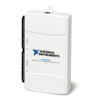
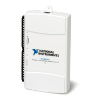
NI USB-621 Series
National Instruments NI USB-621 Series Manuals
Manuals and User Guides for National Instruments NI USB-621 Series. We have
2
National Instruments NI USB-621 Series manuals available for free PDF download: User Manual
National Instruments NI USB-621 Series User Manual (185 pages)
DAQ M Series Bus-Powered M Series USB Devices
Brand:
National Instruments
| Category:
I/O Systems
| Size: 4 MB
Table of Contents
Important Information
3
Table of Contents
5
About this Manual
12
Conventions
12
Related Documentation
13
NI-Daqmx for Windows
13
NI-Daqmx Base (Linux/Mac os X/Labview PDA 8.X)
13
Measurement Studio
15
Device Documentation and Specifications
16
ANSI C Without ni Application Software
16
NET Languages Without ni Application Software
16
Technical Support on the Web
17
Training Courses
17
Chapter 1 Getting Started
18
Installing NI-Daqmx
18
Installing Other Software
18
Installing the Hardware
18
Device Pinouts
18
Device Specifications
19
Applying Signal Labels to the USB-621X
19
USB Cable Strain Relief
20
Mounting the USB-621X
21
Desktop Use
21
DIN Rail Mounting
21
Panel Mounting
22
Chapter 2 DAQ System Overview
24
DAQ Hardware
24
Daq-Stc2
25
Calibration Circuitry
25
Signal Conditioning
26
Sensors and Transducers
26
Cables and Accessories
27
USB-621X Mass Termination Custom Cabling
27
Programming Devices in Software
28
Chapter 3 Connector and LED Information
29
I/O Connector Signal Descriptions
29
+5 V Power
31
+5 V Power as an Output
31
+5 V Power as an Input
31
USB Device Fuse Replacement
31
PWR/ACT LED Indicator
33
Chapter 4 Analog Input
34
Analog Input Range
35
Analog Input Ground-Reference Settings
36
Configuring AI Ground-Reference Settings in Software
38
Multichannel Scanning Considerations
38
Analog Input Data Acquisition Methods
41
Analog Input Digital Triggering
43
Field Wiring Considerations
43
Analog Input Timing Signals
44
AI Sample Clock Signal
47
Using an Internal Source
47
Using an External Source
47
Routing AI Sample Clock to an Output Terminal
47
Other Timing Requirements
47
AI Sample Clock Timebase Signal
48
AI Convert Clock Signal
49
Using an Internal Source
49
Using an External Source
49
Routing AI Convert Clock to an Output Terminal
49
Using a Delay from Sample Clock to Convert Clock
50
Other Timing Requirements
50
AI Convert Clock Timebase Signal
52
AI Hold Complete Event Signal
52
AI Start Trigger Signal
53
Using a Digital Source
53
Routing AI Start Trigger to an Output Terminal
53
AI Reference Trigger Signal
54
Using a Digital Source
55
Routing AI Reference Trigger to an Output Terminal
55
AI Pause Trigger Signal
55
Getting Started with AI Applications in Software
55
Connecting Analog Input Signals on USB-6210/6211/6212 Devices
56
Floating Signal Sources
57
Connecting Floating Signal Sources
58
What Are Floating Signal Sources
58
When to Use Differential Connections with Floating Signal Sources
58
When to Use Referenced Single-Ended (RSE) Connections with Floating Signal Sources
58
When to Use Non-Referenced Single-Ended (NRSE) Connections with Floating Signal Sources
59
Using Differential Connections for Floating Signal Sources
60
Using Non-Referenced Single-Ended (NRSE) Connections for Floating Signal Sources
63
Using Referenced Single-Ended (RSE) Connections for Floating Signal Sources
64
Connecting Ground-Referenced Signal Sources
64
What Are Ground-Referenced Signal Sources
64
When to Use Differential Connections with Ground-Referenced Signal Sources
65
When to Use Non-Referenced Single-Ended (NRSE) Connections with Ground-Referenced Signal Sources
65
When to Use Referenced Single-Ended (RSE) Connections with Ground-Referenced Signal Sources
66
Using Differential Connections for Ground-Referenced Signal Sources
66
Using Non-Referenced Single-Ended (NRSE) Connections for Ground-Referenced Signal Sources
67
Connecting Analog Input Signals on USB-6215/6216/6218 Devices
69
Taking Differential Measurements
69
Taking Referenced Single-Ended (RSE) Measurements
70
Taking Non-Referenced Single-Ended (NRSE) Measurements
71
Chapter 5 Analog Output
72
AO Range
73
Minimizing Glitches on the Output Signal
73
Analog Output Data Generation Methods
73
Analog Output Digital Triggering
74
Connecting Analog Output Signals
75
Analog Output Timing Signals
75
AO Start Trigger Signal
76
Using a Digital Source
76
Routing AO Start Trigger to an Output Terminal
77
AO Pause Trigger Signal
77
Using a Digital Source
78
AO Sample Clock Signal
78
Using an Internal Source
78
Using an External Source
79
Routing AO Sample Clock to an Output Terminal
79
Other Timing Requirements
79
AO Sample Clock Timebase Signal
79
Getting Started with AO Applications in Software
80
Chapter 6 Digital I/O
81
Digital I/O on USB-6210/6211/6215/6218 Devices
81
Static DIO on USB-6210/6211/6215/6218 Devices
82
I/O Protection on USB-6210/6211/6215/6218 Devices
82
Increasing Current Drive on USB-6210/6211/6215/6218 Devices
83
Connecting Digital I/O Signals on USB-6210/6211/6215/6218 Devices
83
Getting Started with DIO Applications in Software on USB-6210/6211/6215/6218 Devices
84
Digital I/O on USB-6212/6216 Devices
84
Static DIO on USB-6212/6216 Devices
85
I/O Protection on USB-6212/6216 Devices
85
Programmable Power-Up States on USB-6212/6216 Devices
86
Increasing Current Drive on USB-6212/6216 Devices
86
Connecting Digital I/O Signals on USB-6212/6216 Devices
86
Getting Started with DIO Applications in Software on USB-6212/6216 Devices
87
Chapter 7 PFI
88
Using PFI Terminals as Timing Input Signals
89
Exporting Timing Output Signals Using PFI Terminals
90
Using PFI Terminals as Static Digital I/Os
90
Connecting PFI Input Signals
91
PFI Filters
91
I/O Protection
93
Programmable Power-Up States
93
Chapter 8 Counters
94
Counter Input Applications
95
Counting Edges
95
Single Point (On-Demand) Edge Counting
95
Buffered (Sample Clock) Edge Counting
96
Controlling the Direction of Counting
97
Pulse-Width Measurement
97
Single Pulse-Width Measurement
97
Buffered Pulse-Width Measurement
98
Period Measurement
99
Single Period Measurement
99
Buffered Period Measurement
100
Semi-Period Measurement
101
Single Semi-Period Measurement
101
Buffered Semi-Period Measurement
101
Frequency Measurement
102
Choosing a Method for Measuring Frequency
106
Position Measurement
108
Measurements Using Quadrature Encoders
108
Measurements Using Two Pulse Encoders
110
Two-Signal Edge-Separation Measurement
111
Single Two-Signal Edge-Separation Measurement
111
Buffered Two-Signal Edge-Separation Measurement
112
Counter Output Applications
113
Simple Pulse Generation
113
Single Pulse Generation
113
Single Pulse Generation with Start Trigger
113
Retriggerable Single Pulse Generation
114
Pulse Train Generation
115
Continuous Pulse Train Generation
115
Frequency Generation
116
Using the Frequency Generator
116
Frequency Division
117
Pulse Generation for ETS
117
Counter Timing Signals
118
Counter N Source Signal
119
Routing a Signal to Counter N Source
119
Routing Counter N Source to an Output Terminal
119
Counter N Gate Signal
120
Routing a Signal to Counter N Gate
120
Routing Counter N Gate to an Output Terminal
120
Counter N aux Signal
120
Routing a Signal to Counter N aux
120
Counter N A, Counter N B, and Counter N Z Signals
121
Routing Signals to A, B, and Z Counter Inputs
121
Counter N Up_Down Signal
121
Counter N HW Arm Signal
121
Routing Signals to Counter N HW Arm Input
122
Counter N Internal Output and Counter N TC Signals
122
Routing Counter N Internal Output to an Output Terminal
122
Frequency Output Signal
122
Routing Frequency Output to a Terminal
122
Default Counter/Timer Pinouts
123
Counter Triggering
124
Other Counter Features
125
Sample Clock
125
Cascading Counters
126
Counter Filters
126
Prescaling
127
Duplicate Count Prevention
128
Example Application that Works Correctly (no Duplicate Counting)
128
Example Application that Works Incorrectly (Duplicate Counting)
129
Example Application that Prevents Duplicate Count
129
Enabling Duplicate Count Prevention in NI-Daqmx
130
Chapter 9 Isolation and Digital Isolators on USB-6215/6216/6218 Devices
131
Digital Isolation
132
Benefits of an Isolated DAQ Device
132
Reducing Common-Mode Noise
133
Creating an AC Return Path
133
Isolated Systems
134
Non-Isolated Systems
134
Chapter 10 Digital Routing and Clock Generation
135
80 Mhz Timebase
135
100 Khz Timebase
135
Chapter 11 Bus Interface
136
USB Signal Stream
136
Data Transfer Methods
136
Changing Data Transfer Methods
137
Chapter 12 Triggering
138
Triggering with a Digital Source
138
Device-Specific Information
140
Appendix B
141
Appendix C
141
Figure
141
USB-6210 Pinout
141
USB-6211/6215 Pinout
143
Appendix A
143
Usb-6211/6215
143
Figure
143
USB-6212/6216 Screw Terminal Pinout
145
USB-6212/6216 Screw Terminal
145
USB-6212/6216 Mass Termination
147
USB-6212/6216 Mass Termination Pinout
148
Usb-6218
152
Figure
152
USB-6218 Pinout
152
Troubleshooting
154
Technical Support and Professional Services
157
Advertisement
National Instruments NI USB-621 Series User Manual (178 pages)
Bus-Powered M Series USB Devices
Brand:
National Instruments
| Category:
Computer Hardware
| Size: 4 MB
Table of Contents
Important Information
3
Table of Contents
5
About this Manual
13
Conventions
13
Related Documentation
14
NI-Daqmx for Windows
14
Labview
14
Labwindows™/CVI
15
Measurement Studio
15
ANSI C Without ni Application Software
15
NET Languages Without ni Application Software
16
Device Documentation and Specifications
16
Training Courses
16
Technical Support on the Web
16
Chapter 1 Getting Started
17
Installing NI-Daqmx
18
Installing Other Software
18
Installing the Hardware
19
Device Pinouts
19
Device Specifications
19
Device Accessories
19
Chapter 2 DAQ System Overview
20
DAQ Hardware
20
Daq-Stc2
21
Calibration Circuitry
21
Signal Conditioning
22
Sensors and Transducers
22
Programming Devices in Software
23
Chapter 3 Connector Information
24
I/O Connector Signal Descriptions
24
+5 V Power
25
+5 V Power as an Output
25
+5 V Power as an Input
26
Chapter 4 Analog Input
27
Analog Input Circuitry
27
Analog Input Range
28
Analog Input Ground-Reference Settings
29
Figure
30
Configuring AI Ground-Reference Settings in Software
31
Figure
31
Multichannel Scanning Considerations
32
Use Low Impedance Sources
32
Appendix B
32
Appendix C
32
Figure
32
Carefully Choose the Channel Scanning Order
33
Avoid Switching from a Large to a Small Input Range
33
Insert Grounded Channel between Signal Channels
33
Minimize Voltage Step between Adjacent Channels
34
Avoid Scanning Faster than Necessary
34
Example 1
34
Example 2
35
Analog Input Data Acquisition Methods
35
Software-Timed Acquisitions
35
Hardware-Timed Acquisitions
35
Buffered
36
Non-Buffered
36
Analog Input Digital Triggering
36
Analog Input Timing Signals
37
AI Sample Clock Signal
40
Using an Internal Source
41
Using an External Source
41
Routing AI Sample Clock Signal to an Output Terminal
41
Other Timing Requirements
41
AI Sample Clock Timebase Signal
42
AI Convert Clock Signal
42
Using an Internal Source
43
Using an External Source
43
Routing AI Convert Clock Signal to an Output Terminal
43
Using a Delay from Sample Clock to Convert Clock
43
Other Timing Requirements
44
AI Convert Clock Timebase Signal
46
AI Hold Complete Event Signal
47
AI Start Trigger Signal
47
Using a Digital Source
47
Routing AI Start Trigger to an Output Terminal
47
AI Reference Trigger Signal
48
Using a Digital Source
49
Routing AI Reference Trigger Signal to an Output Terminal
49
AI Pause Trigger Signal
49
Field Wiring Considerations
37
Getting Started with AI Applications in Software
50
Chapter 5 Connecting AI Signals on the USB-6210/6211 Devices
51
Connecting Floating Signal Sources
53
What Are Floating Signal Sources
53
When to Use Differential Connections with Floating Signal Sources
53
When to Use Referenced Single-Ended (RSE) Connections with Floating Signal Sources
53
When to Use Non-Referenced Single-Ended (NRSE) Connections with Floating Signal Sources
54
Using Differential Connections for Floating Signal Sources
55
Using Non-Referenced Single-Ended (NRSE) Connections for Floating Signal Sources
58
Using Referenced Single-Ended (RSE) Connections for Floating Signal Sources
59
Connecting Ground-Referenced Signal Sources
59
What Are Ground-Referenced Signal Sources
59
When to Use Differential Connections with Ground-Referenced Signal Sources
60
When to Use Non-Referenced Single-Ended (NRSE) Connections with Ground-Referenced Signal Sources
60
When to Use Referenced Single-Ended (RSE) Connections with Ground-Referenced Signal Sources
61
Using Differential Connections for Ground-Referenced Signal Sources
62
Using Non-Referenced Single-Ended (NRSE) Connections for Ground-Referenced Signal Sources
63
Chapter 6 Connecting AI Signals on the USB-6215/6218 Devices
64
Differential Measurements
64
Differential Pairs
64
Referenced Single-Ended (RSE) Measurements
66
Non-Referenced Single-Ended (NRSE) Measurements
67
Chapter 7 Analog Output
68
Analog Output Circuitry
68
AO Range
69
Minimizing Glitches on the Output Signal
69
Analog Output Data Generation Methods
69
Software-Timed Generations
69
Hardware-Timed Generations
69
Analog Output Digital Triggering
71
Connecting Analog Output Signals
71
Analog Output Timing Signals
72
AO Start Trigger Signal
72
Using a Digital Source
72
Routing AO Start Trigger Signal to an Output Terminal
73
AO Pause Trigger Signal
73
Using a Digital Source
73
AO Sample Clock Signal
74
Using an Internal Source
74
Using an External Source
74
Routing AO Sample Clock Signal to an Output Terminal
74
Other Timing Requirements
74
AO Sample Clock Timebase Signal
75
Getting Started with AO Applications in Software
76
Chapter 8 Digital I/O
77
Static DIO
78
I/O Protection
78
Increasing Current Drive
78
Connecting Digital I/O Signals
79
Getting Started with DIO Applications in Software
80
Chapter 9 Counters
81
Counter Input Applications
82
Counting Edges
82
Single Point (On-Demand) Edge Counting
82
Buffered (Sample Clock) Edge Counting
83
Non-Cumulative Buffered Edge Counting
84
Controlling the Direction of Counting
84
Pulse-Width Measurement
85
Single Pulse-Width Measurement
85
Buffered Pulse-Width Measurement
85
Period Measurement
86
Single Period Measurement
87
Buffered Period Measurement
87
Semi-Period Measurement
89
Single Semi-Period Measurement
89
Buffered Semi-Period Measurement
89
Frequency Measurement
90
Method 1-Measure Low Frequency with One Counter
90
Method 1B-Measure Low Frequency with One Counter (Averaged)
91
Method 2-Measure High Frequency with Two Counters
91
Method 3-Measure Large Range of Frequencies Using Two Counters
92
Choosing a Method for Measuring Frequency
93
Position Measurement
95
Measurements Using Quadrature Encoders
95
Measurements Using Two Pulse Encoders
97
Two-Signal Edge-Separation Measurement
98
Single Two-Signal Edge-Separation Measurement
98
Buffered Two-Signal Edge-Separation Measurement
99
Counter Output Applications
100
Simple Pulse Generation
100
Single Pulse Generation
100
Single Pulse Generation with Start Trigger
100
Retriggerable Single Pulse Generation
101
Pulse Train Generation
102
Continuous Pulse Train Generation
102
Frequency Generation
103
Using the Frequency Generator
103
Frequency Division
104
Pulse Generation for ETS
104
Counter Timing Signals
105
Counter N Source Signal
106
Routing a Signal to Counter N Source
106
Routing Counter N Source to an Output Terminal
106
Counter N Gate Signal
107
Routing a Signal to Counter N Gate
107
Routing Counter N Gate to an Output Terminal
107
Counter N aux Signal
107
Routing a Signal to Counter N aux
107
Counter N A, Counter N B, and Counter N Z Signals
108
Routing Signals to A, B, and Z Counter Inputs
108
Counter N Up_Down Signal
108
Counter N HW Arm Signal
108
Routing Signals to Counter N HW Arm Input
108
Counter N Internal Output and Counter N TC Signals
109
Routing Counter N Internal Output to an Output Terminal
109
Frequency Output Signal
109
Routing Frequency Output to a Terminal
109
Default Counter/Timer Pinouts
109
Counter Triggering
111
Arm Start Trigger
111
Start Trigger
111
Pause Trigger
111
Other Counter Features
112
Sample Clock
112
Cascading Counters
113
Counter Filters
113
Prescaling
114
Duplicate Count Prevention
115
Example Application that Works Correctly (no Duplicate Counting)
116
Example Application that Works Incorrectly (Duplicate Counting)
117
Example Application that Prevents Duplicate Count
117
Enabling Duplicate Count Prevention in NI-Daqmx
118
Chapter 10 PFI
119
Using PFI Terminals as Timing Input Signals
120
Exporting Timing Output Signals Using PFI Terminals
121
Using PFI Terminals as Static Digital I/Os
121
Connecting PFI Input Signals
121
PFI Filters
122
I/O Protection
124
Programmable Power-Up States
124
Chapter 11 Isolation and Digital Isolators
125
Digital Isolation
126
Benefits of an Isolated DAQ Device
126
Reducing Common-Mode Noise
126
Creating an AC Return Path
127
Isolated Systems
127
Non-Isolated Systems
127
Chapter 12 Digital Routing and Clock Generation
129
80 Mhz Timebase
129
100 Khz Timebase
130
Chapter 13 Bus Interface
131
USB Signal Streams
131
Data Transfer Methods
131
USB Signal Stream
131
Programmed I/O
132
Changing Data Transfer Methods
132
Chapter 14 Triggering
133
Triggering with a Digital Source
133
Appendix A Device-Specific Information
135
USB-6210 Pinout
135
Usb-6211/6215
138
Usb 6218
141
USB 6218 Pinout
141
Troubleshooting
145
Analog Input
145
Analog Output
147
Technical Support and Professional Services
148
Advertisement
Related Products
National Instruments NI 6239
National Instruments NI 9222
National Instruments NI 9265
National Instruments NI 9208E
National Instruments NI 9225
National Instruments NI 9219E
National Instruments NI-9244
National Instruments NI 6738
National Instruments NI 6739
National Instruments NI PS-26
National Instruments Categories
Control Unit
I/O Systems
Controller
Computer Hardware
Measuring Instruments
More National Instruments Manuals
Login
Sign In
OR
Sign in with Facebook
Sign in with Google
Upload manual
Upload from disk
Upload from URL