Sign In
Upload
Manuals
Brands
Motorola Manuals
Motherboard
MCP750
Motorola MCP750 CompactPCI Single Board Manuals
Manuals and User Guides for Motorola MCP750 CompactPCI Single Board. We have
2
Motorola MCP750 CompactPCI Single Board manuals available for free PDF download: Installation And Use Manual
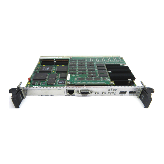
Motorola MCP750 Installation And Use Manual (163 pages)
Hot Swap CompactPCI Single Board Computer
Brand:
Motorola
| Category:
Single board computers
| Size: 23 MB
Table of Contents
Installation and Use
2
Safety Summary
4
EMI Caution
5
Lithium Battery Caution
5
Table of Contents
8
About this Manual
16
Summary of Changes
16
Overview of Contents
17
Comments and Suggestions
18
Conventions Used in this Manual
18
1Hardware Preparation and Installation
20
Introduction
20
Figure 1-1. MCP750HA Base Board Block Diagram
21
Equipment Required
22
Overview of Start-Up Procedure
23
Table 1-1. Startup Overview
23
Unpacking Instructions
24
Flash Bank Selection (J9)
25
Hardware Configuration
25
MCP750HA Base Board Preparation
25
Figure 1-2. MCP750HA Switches, Headers, Connectors, and Leds
27
Compact FLASH Memory Card Installation
28
ESD Precautions
28
Hardware Installation
28
Figure 1-3. Compact FLASH Placement on MCP750HA
29
RAM300 Memory Mezzanine Installation
30
Figure 1-4. RAM300 Placement on MCP750HA
31
PMC Module Installation
32
Figure 1-5. PMC Module Placement on MCP750HA
33
MCP750HA Module Installation
34
Figure 1-6. MCP750HA Board Insertion Sequence
36
MCP750HA Module Power Requirements
37
System Considerations
37
Applying Power
38
Introduction
38
Figure 2-1. Ppcbug System Startup
39
Memory Maps
39
Default Processor Memory Map
40
Processor Memory Map
40
Table 2-1. Processor Default View of the Memory Map
40
PCI Local Bus Memory Map
41
Compactpci Memory Map
42
PCI Arbitration
42
Interrupt Handling
43
DMA Channels
44
Sources of Reset
44
Table 2-2. PBC DMA Channel Assignments
44
Endian Issues
45
Table 2-3. Classes of Reset and Effectiveness
45
PCI and Ethernet
46
PCI Domain
46
Processor/Memory Domain
46
Role of the Raven ASIC
46
3Functional Description
47
Features
47
Introduction
47
Table 3-1. MCP750HA Features
47
General Description
48
Figure 3-1. MCP750HA Block Diagram
50
Block Diagram
51
Compactpci Interface
51
Hot Swap Circuitry
51
PCI Expansion Connector (J4)
52
Domain Ownership
53
Figure 3-2. Active/Passive System
53
Ethernet Interface
54
PCI Mezzanine Interface
55
Asynchronous Serial Ports
56
PC97307 ISA Super I/O Device
56
Floppy Disk/Tape Drive Controller
57
Parallel Port/Printer Interface
57
Keyboard and Mouse Interface
58
PCI Peripheral Bus Controller (PBC)
58
EIDE Series Termination
59
Real-Time Clock/Nvram/Watchdog Timer Function
59
Table 3-2. Series Termination for Ultra DMA EIDE
59
Programmable Timers
60
Raven General Purpose Timers
60
Interval Timers
61
M48T559 Watchdog Timer
61
Raven Watchdog Timers
61
16-Bit Timers
62
Serial Communications Interface
62
MCP750HA Board Identifier
63
Table 3-3. Old CPU Configuration Register
63
Z8536 CIO Device
63
Base Module Feature Register
64
Table 3-4. Base Module Status Register
64
Figure 3-3. Serial Port Signal Multiplexing
65
Serial Port Signal Multiplexing
65
Signal Multiplexing (MX)
65
Table 3-5. Multiplexing Sequence of the MX Function
66
ABORT(ABT) Switch (S2)
67
Figure 3-4. MX Signal Timings
67
RESET(RST) Switch (S1)
67
Front Panel Indicators (DS1 - DS4)
68
Reset and Abort Header (J21)
68
Fuses and Polyswitches (Resettable Fuses)
69
Speaker Control
69
Table 3-6. Fuse Assignments
69
Flash Memory
70
MPC750 Processor
70
Compact FLASH Memory Card
71
RAM300 Memory Module
71
TMCP700 Transition Module
71
Serial Interface Modules
72
Table 3-7. SIM Type Identification
72
4Connector Pin Assignments
74
Common Connectors
74
MCP750HA Connectors
74
Compactpci Connectors (J1/J2)
75
Table 4-1. Compactpci Connector J1
75
Table 4-2. Compactpci Connector J2
76
Compactpci Hsc/User I/O Connector (J3)
77
Table 4-3. J3 User I/O Connector
77
Local Bus Expansion Connector (J4)
78
Table 4-4. J4 Local PCI Expansion Connector
78
Table 4-5. J5 User I/O Connector
79
Table 4-6. PCI Mezzanine Card Connector
80
Table 4-7. PCI Mezzanine Card Connector
82
10Baset/100Basetx Connector (J8)
83
Front USB Connectors (J17/J18)
83
Table 4-8. USB 0 Connector J18
83
Table 4-9. USB 1 Connector J17
83
COM1 Connector (J15)
84
Table 4-10. 10Baset/100Basetx Connector J8
84
Table 4-11. COM1 Connector J15
84
Debug Connector (J16)
85
Reset and Abort Header (J21)
85
Table 4-12. Reset/Abort Header J21
85
Table 4-13. Debug Connector (J16)
85
DRAM Mezzanine Connector (J7)
89
Table 4-14. DRAM Mezzanine Connector (J7)
89
EIDE Compact FLASH Connector (J20)
92
Table 4-15. EIDE Compact FLASH Connector J20
92
Ppcbug Basics
94
Ppcbug Overview
94
Memory Requirements
96
MPU, Hardware, and Firmware Initialization
96
Ppcbug Implementation
96
Using Ppcbug
99
Debugger Commands
100
Standard Commands
100
Table 5-1. Debugger Commands
100
High Availability Commands
104
Table 5-2. High Availability Specific Debugger Commands
104
Table 5-3. Unsupported Debugger Commands
104
Unsupported Commands
104
Debugger System Call Interfaces
105
High Availability System Call Interfaces
105
Table 5-4. High Availability Specific Debugger System Calls
105
Unsupported System Call Interfaces
105
Bug Diagnostics
106
Table 5-5. Unsupported Debugger System Calls
106
Diagnostic Tests
107
Table 5-6. Specific Diagnostic Test Groups
107
High Availability Diagnostic Commands
108
Table 5-7. Ppcbug Diagnostic Commands for High Availability Systems
108
Table 5-8. Unsupported Ppcbug Diagnostic Commands
109
Unsupported Ppcbug Diagnostic Commands
109
6CNFG and ENV Commands
110
CNFG - Configure Board Information Block
110
Overview
110
ENV - Set Environment
111
Configuring the Ppcbug Parameters
112
APPENDIX A Specifications
124
Specifications
124
Table A-1. MCP750HA Specifications
124
Cooling Requirements
125
EMC Compliance
125
Introduction
127
Unpacking Instructions
127
TMCP700 Transition Module Preparation
127
Serial Ports 1 and 2
130
Configuration of Serial Ports 3 and 4
130
ESD Precautions
135
TMCP700 Transition Module Installation
135
TMCP700 Transition Module
137
Compactpci Connectors (J3/J4/J5
138
Serial Ports 1 and 2 (J10/J11) (TMCP700 I/O Mode
138
Table B-1. Serial Connections - Ports 1 and 2 (J10 and J11) (TMCP700
138
Serial Ports 3 and 4 (J6/J24) (TMCP700 I/O Mode
139
Table B-2. Serial Connections - Ports 3 and 4 (J6 and J24) (TMCP700
139
Parallel Connector (J7) (TMCP700 I/O Mode
140
Table B-3. Parallel Connector J7 (TMCP700
140
Keyboard/Mouse Connector (J16) (TMCP700 I/O Mode
141
USB Connectors (J18/J19) (Optional TMCP700 I/O Mode
141
Table B-4. Keyboard/Mouse Connector J16 (TMCP700
141
EIDE Connector (J15
142
Table B-5. EIDE Connector (J15
142
Floppy Port Connector (J17
143
5VDC Power Connector (J14
143
Table B-6. Floppy Connector (J17
143
Speaker Output Connector (J13
144
PMC I/O Connectors (J2/J21
144
Table B-7. +5Vdc Power Connector (J14
144
Table B-8. Speaker Output Connector (J13
144
Table B-9. PMC I/O Connector (J2
144
Table B-10. PMC I/O Connector (J21
146
Crelated Documentation
148
Motorola Computer Group Documents
148
Table C-1. Motorola Computer Group Documents
148
Manufacturers' Documents
149
Table C-2. Manufacturer's Documents
149
Related Specifications
150
Table C-3. Related Specifications
159
Advertisement
Motorola MCP750 Installation And Use Manual (154 pages)
CompactPCI Single Board Computer
Brand:
Motorola
| Category:
Motherboard
| Size: 1 MB
Table of Contents
Do Not Operate in an Explosive Atmosphere
3
Do Not Substitute Parts or Modify Equipment
3
Ground the Instrument
3
Safety Summary
3
Emi Caution
4
Table of Contents
7
About this Manual
14
Summary of Changes
15
Overview of Contents
15
Comments and Suggestions
16
Conventions Used in this Manual
16
CHAPTER 1 Hardware Preparation and Installation
18
Introduction
18
Figure 1-1. MCP750 Base Board Block Diagram
19
Equipment Required
20
Overview of Start-Up Procedure
21
Table 1-1. Startup Overview
21
Unpacking Instructions
22
Hardware Configuration
22
MCP750 Base Board Preparation
23
Flash Bank Selection (J6)
23
Figure 1-2. MCP750 Switches, Headers, Connectors, Fuses, Leds
25
TMCP700 Transition Module Preparation
26
Figure 1-3. TMCP700 Connector and Header Locations
27
Configuration of Serial Ports 3 and 4
28
Serial Ports 1 and 2
28
Figure 1-4. MCP750/TMCP700 Serial Ports 1 and 2 (DTE Only)
30
Figure 1-5. TMCP700 Serial Ports 3 and 4 DCE Configuration
31
Figure 1-6. TMCP700 Serial Ports 3 and 4 DTE Configuration
32
ESD Precautions
33
Hardware Installation
33
Compact FLASH Memory Card Installation
33
Figure 1-7. Compact FLASH Placement on MCP750
34
RAM300 Memory Mezzanine Installation
35
Figure 1-8. RAM300 Placement on MCP750
36
PMC Module Installation
37
Figure 1-9. PMC Module Placement on MCP750
38
MCP750 Module Installation
39
TMCP700 Transition Module Installation
41
Figure 1-10. TMCP700/MCP750 Mating Configuration
42
System Considerations
43
MCP750 Module Power Requirements
43
CHAPTER 2 Operating Instructions
45
Introduction
45
Applying Power
45
Memory Maps
46
Figure 2-1. Ppcbug System Startup
46
Processor Memory Map
47
Default Processor Memory Map
47
Table 2-1. Processor Default View of the Memory Map
47
PCI Local Bus Memory Map
48
Compactpci Memory Map
49
PCI Arbitration
49
Interrupt Handling
50
DMA Channels
51
Sources of Reset
51
Table 2-2. PBC DMA Channel Assignments
51
Endian Issues
52
Processor/Memory Domain
52
Table 2-3. Classes of Reset and Effectiveness
52
Role of the Raven ASIC
53
PCI Domain
53
PCI and Ethernet
53
CHAPTER 3 Functional Description
54
Introduction
54
Features
54
Table 3-1. MCP750 Features
54
General Description
55
Block Diagram
57
Figure 3-1. MCP750 Block Diagram
57
Compactpci Interface
58
Ethernet Interface
58
PC87307 ISA Super I/O Device (ISASIO)
60
Asynchronous Serial Ports
61
Floppy Disk/Tape Drive Controller
61
Parallel Port/Printer Interface
61
Keyboard and Mouse Interface
62
PCI Mezzanine Interface
60
PCI Peripheral Bus Controller (PBC)
62
Real-Time Clock/Nvram/Watchdog Timer Function
63
Programmable Timers
64
Raven General Purpose Timers
64
Raven Watchdog Timers
64
16-Bit Timers
65
Interval Timers
65
M48T559 Watchdog Timer
65
Serial Communications Interface
66
Z8536 CIO Device
66
Base Module Feature Register
67
Serial Port Signal Multiplexing
67
Figure 3-2. Serial Port Signal Multiplexing
68
Signal Multiplexing (MX)
68
Table 3-2. Multiplexing Sequence of the MX Function
69
ABORT(ABT) Switch (S2)
70
RESET(RST) Switch (S1)
70
Figure 3-3. MX Signal Timings
70
Front Panel Indicators (DS1 - DS4)
70
Fuses and Polyswitches (Resettable Fuses)
71
Table 3-3. Fuse Assignments
71
MPC750 Processor
72
Speaker Control
72
Flash Memory
73
RAM300 Memory Module
73
Compact FLASH Memory Card
74
TMCP700 Transition Module
74
Serial Interface Modules
75
Table 3-4. SIM Type Identification
75
CHAPTER 4 Connector Pin Assignments
76
MCP750 Connectors
76
Common Connectors
77
Compactpci Connectors (J1/J2)
77
Table 4-1. J1 Compactpci Connector
77
Table 4-2. J2 Compactpci Connector
78
Compactpci User I/O Connector (J3)
79
Table 4-3. J3 User I/O Connector
80
Local Bus Expansion Connector (J4)
81
Table 4-4. J4 Local PCI Expansion Connector
81
User I/O Connector (J5)
82
Table 4-5. J5 User I/O Connector
82
PCI Mezzanine Card Connectors (J11/J12/J13/J14)
83
Table 4-6. PCI Mezzanine Card Connector
83
Table 4-7. PCI Mezzanine Card Connector
84
Front USB Connectors (J17/J18)
85
Table 4-8. USB 0 Connector J18
85
10/100 Base-T Connector (J8)
86
Table 4-9. USB 1 Connector J17
86
Table 4-10. 10/100 Base-T Connector J8
86
COM1 Connector (J15)
87
Debug Connector (J19)
87
Table 4-11. COM1 Connector J15
87
Table 4-12. Debug Connector (J19)
87
DRAM Mezzanine Connector (J10)
92
Table 4-13. DRAM Mezzanine Connector (J10)
92
EIDE Compact FLASH Connector (J9)
95
Table 4-14. EIDE Compact FLASH Connector J9
95
TMCP700 Transition Module
96
Compactpci Connectors (J3/J4/J5)
97
Serial Ports 1 and 2 (J10/J11) (TMCP700 I/O Mode)
97
Table 4-15. Serial Connections - Ports 1 and 2 (J10 and J11) (TMCP700 )
97
Serial Ports 3 and 4 (J6/J24) (TMCP700 I/O Mode)
98
Table 4-16. Serial Connections - Ports 3 and 4 (J6 and J24) (TMCP700)
98
Parallel Connector (J7) (TMCP700 I/O Mode)
99
Table 4-17. Parallel Connector J7 (TMCP700)
99
Keyboard/Mouse Connector (J16) (TMCP700 I/O Mode)
100
USB Connectors (J18/J19) (Optional TMCP700 I/O Mode)
100
Table 4-18. Keyboard/Mouse Connector J16 (TMCP700)
100
EIDE Connector (J15)
101
Table 4-19. EIDE Connector (J15)
101
Floppy Port Connector (J17)
102
5Vdc Power Connector (J14)
102
Table 4-20. Floppy Connector (J17)
102
Speaker Output Connector (J13)
103
PMC I/O Connectors (J2/J21)
103
Table 4-21. +5Vdc Power Connector (J14)
103
Table 4-22. Speaker Output Connector (J13)
103
Table 4-23. PMC I/O Connector (J2)
103
Table 4-24. PMC I/O Connector (J21)
105
CHAPTER 5 Ppcbug
107
Ppcbug Overview
107
Ppcbug Basics
107
Memory Requirements
109
Ppcbug Implementation
109
MPU, Hardware, and Firmware Initialization
109
Using Ppcbug
112
Debugger Commands
113
Standard Commands
113
Table 5-1. Debugger Commands
113
High Availability Supported Commands
117
Table 5-2. High Availability Specific Debugger Commands
117
Unsupported Commands
118
Debugger System Call Interfaces
118
Supported System Call Interfaces
118
Table 5-3. Unsupported Debugger Commands
118
Table 5-4. High Availability Specific Debugger System Calls
118
Unsupported System Call Interfaces
119
Bug Diagnostics
119
Table 5-5. Unsupported Debugger System Calls
119
Diagnostic Tests
120
Table 5-6. Specific Diagnostic Test Groups
120
High Availability Specific Ppcbug Diagnostic Commands
121
Table 5-7. Ppcbug Diagnostic Commands for High Availability Systems
121
Unsupported Ppcbug Diagnostic Commands
121
Table 5-8. Unsupported Ppcbug Diagnostic Commands
122
CHAPTER 6 CNFG and ENV Commands
123
Overview
123
CNFG - Configure Board Information Block
123
ENV - Set Environment
124
Configuring the Ppcbug Parameters
125
APPENDIX A Specifications
134
Specifications
134
Table A-1. MCP750 Specifications
134
Cooling Requirements
135
EMC Compliance
135
APPENDIX B Related Documentation
137
Motorola Computer Group Documents
137
Table B-1. Motorola Computer Group Documents
137
Manufacturers' Documents
138
Table B-2. Manufacturers' Documents
138
Related Specifications
142
Table B-3. Related Specifications
145
Advertisement
Related Products
Motorola MC68HC908JB8
Motorola MC145192EVK
Motorola MC145202EVK
Motorola MC145191
Motorola MC145200
Motorola MC145201
Motorola MC145190EVK
Motorola MC145191EVK
Motorola MC145201EVK
Motorola MC145200EVK
Motorola Categories
Cell Phone
Two-Way Radio
Baby Monitor
Cordless Telephone
Radio
More Motorola Manuals
Login
Sign In
OR
Sign in with Facebook
Sign in with Google
Upload manual
Upload from disk
Upload from URL