Sign In
Upload
Manuals
Brands
Motorola Manuals
Portable Radio
ASTRO Digital XTS 3000
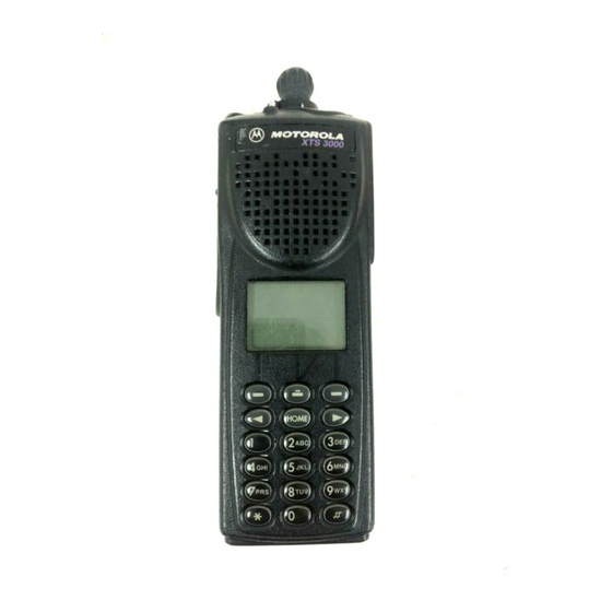
Motorola ASTRO Digital XTS 3000 Manuals
Manuals and User Guides for Motorola ASTRO Digital XTS 3000. We have
8
Motorola ASTRO Digital XTS 3000 manuals available for free PDF download: Service Manual, User Manual, Detailed Service Manual, Basic Service Manual, Operator's Manual
Motorola ASTRO Digital XTS 3000 Service Manual (236 pages)
Brand:
Motorola
| Category:
Portable Radio
| Size: 11.85 MB
Table of Contents
Table of Contents
5
Foreword
2
Table of Contents
5
Portable Radio Model Numbering System
11
ASTRO Digital XTS 3000 Model Chart ("A" Models)
12
ASTRO Digital XTS 3000 Model Chart ("B" Models)
13
ASTRO Digital XTS 3000 R (Ruggedized) Model Chart
14
ASTRO Digital XTS 3000 R (Ruggedized) Yellow Model Chart
15
Glossary
17
Introduction
21
General
21
Notations Used in this Manual
22
XTS 3000 R Radios Only
23
General Overview of an ASTRO Digital XTS 3000 Radio
25
Analog Mode of Operation
26
ASTRO Mode (Digital Mode) of Operation
26
Controller Board Overview
27
Transceiver Board Overview
27
Figure 2-1 Controller Board/Vocoder Board Interconnection
28
Vocoder Board Overview
29
Vocoder Board
29
Radio Power
31
Introduction to this Section
31
General
31
B+ Routing for VHF/UHF Transceiver Boards
31
B+ Routing for VHF/UHF Transceiver Boards
32
B+ Routing for 800Mhz Transceiver Boards
33
B+ and +5V Routing for Controller and Vocoder Boards
34
Figure 3-3 B+ Routing for Controller Board
35
Figure
36
Frequency Generation Unit (FGU)
37
VHF/UHF Transceiver Board Detailed Theory of Operation
37
Introduction to this Section
37
Antenna Switch
39
Receiver Front End
39
Receiver Back End
40
Transmitter
41
Harmonic Filter
41
RF Power Amplifier Module
41
ALC Circuits
41
800Mhz Transceiver Board Detailed Theory of Operation
43
Introduction to this Section
43
Frequency Synthesis
43
Antenna Switch
45
Receiver Front End
45
Receiver Back End
46
Transmitter
47
Vocoder and Controller Boards Detailed Theory of Operation
49
Introduction to this Section
49
General
49
Vocoder Board
49
Controller Board
51
Audio Power Amplifier Steering
52
Switching Regulator
53
RX Signal Path
54
TX Signal Path
56
Controller Bootstrap and Asynchronous Buses
58
Figure
58
Vocoder Bootstrap
59
SPI Bus Interface
60
Universal Connector and Option Selects
60
Figure
60
Keypad and Display Module
61
Controls and Control Top Flex
61
Control Top Flex
61
Table 6-1 Option Select Functions
61
Figure
62
Controller Memory Map
63
Vocoder Memory Map
65
MCU System Clock
66
DSP System Clock
66
Radio Power-Up/Power-Down Sequence
67
Introduction
69
Secure Modules
69
Circuit Description
70
Troubleshooting
70
Secure Operations
70
Error 09/10, Error 09/90
70
Keyload
70
Disassembly/Reassembly Procedures
71
Introduction to this Section
71
Disassembly
71
Reassembly
73
Specialized Test Equipment
75
Vacuum Pump Kit, NLN9839
75
General Information
75
Ensuring Radio Submersibility
75
Introduction
75
Pressure Pump Kit, NTN4265
76
Miscellaneous
76
Hardware
76
Disassembly and Reassembly
76
Disassembly
76
Reassembly
76
Vacuum Test
76
General
76
Conducting the Test
77
Pressure Test
77
General
77
Conducting the Test
78
Controls Seal
79
Troubleshooting Leak Areas
79
Antenna Bushing Seal
79
Housing
79
Frequency Switch, Toggle, and On/Off/Volume Control Switch
80
Main Seal
81
Battery Contact and Battery Contact Seal
81
Keypad
82
Vacuum Port Seal
82
Vent Port Seal
82
Housing Assembly Replacement
83
Universal Connector Bracket
83
Troubleshooting Procedures
85
Introduction to this Section
85
Handling Precautions
85
Voltage Measurement and Signal Tracing
86
Power-Up Self-Check Errors
87
Power-Up Sequence
87
Standard Bias Table
90
Troubleshooting Charts
91
Introduction to this Section
91
Chart 1. 800 Mhz Radio Main
93
Chart 2. VHF/UHF Radio Main
94
Chart 3. Radio Power-Up Fail
95
Chart 4. Bootstrap Fail
96
Chart 5. DC Supply Failure
97
Chart 6. 01/81 Host ROM Checksum Failure
98
Chart 7. 01/82 or 002, External EEPROM Checksum Failure
99
Chart 8. 01/84 SLIC Initialization Failure
100
Chart 9. 01/88 MCU (Host ΜC) External SRAM
101
Chart 10. 01/92, Internal EEPROM Checksum Failure
102
Chart 11. 02/A0, ADSIC Checksum Failure
103
Chart 12. 02/81, DSP ROM Checksum Failure
104
Chart 13. 02/88, DSP External SRAM Failureu414
105
Chart 14. 02/90, General DSP Hardware Failure
106
Table 9-1 Table
106
Chart 15. 09/10, Secure Hardware Failure
107
Chart 16. 09/90, Secure Hardware Failure
108
Chart 17. Key Load Fail
109
Chart 18. Button Test
110
Chart 19. Keypad Error
111
Chart 20. Volume Set Error
112
Chart 21. Zone/Channel Select Error
113
Chart 22. Top/Side Button Error
114
Chart 23. Radio Power-Up Fail
115
Chart 24. Bootstrap Fail
116
Chart 25. 800 Mhz no TX Deviation
117
Chart 26. VHF/UHF no TX Deviation
117
Chart 27. no RX Audio
118
Chart 28. VHF/UHF/800 Mhz Receiver RF
119
Chart 29. VHF/UHF Frequency Generation Unit (FGU)
120
Chart 30. 800 Mhz Frequency Generation Unit (FGU)
120
Chart 31. VHF/UHF Voltage Controlled Oscillator (VCO)
121
Chart 32. 800 Mhz Voltage Controlled Oscillator (VCO)
122
Chart 33. 800 Mhz DC Switch
123
Chart 34. VHF/UHF DC Switch
123
Chart 35. 800 Mhz Transmitter RF
124
Chart 36. VHF/UHF Transmitter RF
125
Chart 37. VHF/UHF Only, VCO Crossover Frequency Tune
126
Introduction to this Section
127
Troubleshooting Waveforms
127
Waveforms
127
Introduction to this Section
133
Troubleshooting Diagrams
133
Interconnect Diagram, Schematics with Parts Lists, Circuit Board Details, Exploded Views with Parts Lists
137
Controller Board
138
Radio Interconnect Block Diagram
138
NLD8898B/C/D VHF RF Board Schematic Diagram, Sheet 1 of 3
139
NLD8898B/C/D VHF RF Board Schematic Diagram, Sheet 2 of 3
140
NLD8898B/C/D VHF RF Board Schematic Diagram, Sheet 3 of 3
141
NLD8898B/C/D VHF RF Board Component Location Detail and Parts List
142
NLD8898H VHF RF Board Schematic Diagram, Sheet 1 of 3
144
NLD8898H VHF RF Board Schematic Diagram, Sheet 2 of 3
145
NLD8898H VHF RF Board Schematic Diagram, Sheet 3 of 3
146
NLD8898H VHF RF Board Component Location Detail and Parts List
147
NLE4249A UHF Range 1 RF Board Schematic Diagram, Sheet 1 of 3
149
NLE4249A UHF Range 1 RF Board Schematic Diagram, Sheet 2 of 3
150
NLE4249A UHF Range 1 RF Board Schematic Diagram, Sheet 3 of 3
151
NLE4249A UHF Range 1 RF Board Component Location Detail and Parts List
152
NLE4249D, NLE4250E UHF Range 1 and 2 RF Board Component Location Detail and Parts List
157
NLE4249E, NLE4250F UHF Range 1 and 2 RF Board Schematic Diagram, Sheet 1 of 3
160
NLE4249E, NLE4250F UHF Range 1 and 2 RF Board Schematic Diagram, Sheet 2 of 3
161
NLE4249E, NLE4250F UHF Range 1 and 2 RF Board Schematic Diagram, Sheet 3 of 3
162
NLE4249E, NLE4250F UHF Range 1 and 2 RF Board Component Location Detail and Parts List
163
Component Location Detail and Parts List
169
NUF6472B 800 Mhz RF Board Schematic Diagram, Sheet 1 of 3
171
NUF6472B 800 Mhz RF Board Schematic Diagram, Sheet 2 of 3
172
NUF6472B 800 Mhz RF Board Schematic Diagram, Sheet 3 of 3
173
NUF6472B 800 Mhz RF Board Component Location Detail and Parts List
174
NUF6472D 800 Mhz RF Board Schematic Diagram, Sheet 1 of 3
176
NUF6472D 800 Mhz RF Board Schematic Diagram, Sheet 2 of 3
177
NUF6472D 800 Mhz RF Board Schematic Diagram, Sheet 3 of 3
178
NUF6472D 800 Mhz RF Board Component Location Detail and Parts List
179
NCN6128B Controller Board Schematic Diagram, Sheet 1 of 4
182
NCN6128B Controller Board Schematic Diagram, Sheet 2 of 4
183
NCN6128B Controller Board Component Location Detail, Sheet 1 of 2
186
NCN6128B Controller Board Component Location Detail, Sheet 2 of 2
187
NCN6167A Controller Board Schematic Diagram, Sheet 1 of 4
190
NCN6167A Controller Board Schematic Diagram, Sheet 2 of 4
191
NCN6167A Controller Board Schematic Diagram, Sheet 3 of 4
192
NCN6167A Controller Board Schematic Diagram, Sheet 4 of 4
193
NCN6167A Controller Board Component Location Detail, Sheet 1 of 2
194
NCN6167A Controller Board Component Location Detail, Sheet 2 of 2
195
NCN6167C Controller Board Schematic Diagram, Sheet 1 of 4
198
NCN6167C Controller Board Schematic Diagram, Sheet 2 of 4
199
NCN6167C Controller Board Schematic Diagram, Sheet 3 of 4
200
NCN6167C Controller Board Schematic Diagram, Sheet 4 of 4
201
NCN6167C Controller Board Component Location Detail, Sheet 1 of 2
202
NCN6167C Controller Board Component Location Detail, Sheet 2 of 2
203
NCN6167H Controller Board Schematic Diagram, Sheet 1 of 4
206
NCN6167H Controller Board Schematic Diagram, Sheet 2 of 4
207
NCN6167H Controller Board Schematic Diagram, Sheet 3 of 4
208
NCN6167H Controller Board Schematic Diagram, Sheet 4 of 4
209
NCN6167H Controller Board Component Location Detail, Sheet 1 of 2
210
NCN6167H Controller Board Component Location Detail, Sheet 2 of 2
211
NTN8250C/D Vocoder Board Schematic Diagram, Sheet 1 of 2
214
NTN8250C/D Vocoder Board Schematic Diagram, Sheet 2 of 2
215
NTN8250C/D Vocoder Board Component Location Detail
216
NTN8250F Vocoder Board Schematic Diagram, Sheet 1 of 2
218
NTN8250F Vocoder Board Schematic Diagram, Sheet 2 of 2
219
NTN8250F Vocoder Board Component Location Detail
220
NTN8250G Vocoder Board Schematic Diagram, Sheet 1 of 2
222
NTN8250G Vocoder Board Schematic Diagram, Sheet 2 of 2
223
NTN8250G Vocoder Board Component Location Detail
224
0105956V33 Controller Flex Circuit Detail
228
0105956V33 Controller Flex Schematic and Parts List
229
Model I Exploded View and Parts List
230
Models II and III Exploded View and Parts List
231
Advertisement
Motorola ASTRO Digital XTS 3000 Service Manual (84 pages)
Brand:
Motorola
| Category:
Radio
| Size: 1.33 MB
Table of Contents
Table of Contents
5
Safety Information
7
Chapter 1 : Safety Information
9
Chapter 2: Model Charts and Test Specifications
9
Specifications for VHF Radios
10
Specifications for UHF Radios
12
Specifications for 800 Mhz Radios
15
Chapter 3: Overview
19
Notations Used in this Manual
19
Radio Description
20
Flashport
21
Chapter 4: Basic Maintenance
23
Preventive Maintenance
23
Inspection
23
Cleaning
23
Cleaning External Plastic Surfaces
24
Handling Precautions
24
XTS 3000 R Radios Only
24
Chapter 5: Recommended Test Equipment and Service Aids
27
Recommended Test Equipment
27
Service Aids
28
Field Programming Equipment
29
Chapter 6: Performance Checks
31
Setup
31
Test Mode
32
Entering Test Mode
32
RF Test Mode
33
Display Description
34
Control Top and Keypad Test Mode
35
Chapter 7: ALIGNMENT PROCEDURE
39
General
39
Reference Oscillator
42
Preventative Maintenance
42
Reference Oscillator Alignment
42
Initial Setup Using R-2670 and 8900 Series Analyzers
43
Transmit Power Alignment
45
RSS and CPS Procedures
45
Transmit Deviation Balance (Compensation) Alignment
46
RSS and CPS Procedures
47
Transmit Deviation Limit Alignment
48
RSS and CPS Procedures
49
Front End Filter Alignment (VHF and UHF Only)
51
RSS and CPS Procedures
52
Bit Error Rate Testing
54
Chapter 8: Basic Removal/Installation Procedures
55
Antenna
55
Installing the Antenna
55
Removing the Antenna
55
Battery
56
Installing the Battery
57
Removing the Battery
57
Belt Clip
58
Installing the Belt Clip
58
Removing the Belt Clip
59
Universal Connector Cover
59
Installing the Universal Connector Cover
60
Removing the Universal Connector Cover
60
Frequency Knob
61
Installing the Frequency Knob
61
Removing the Frequency Knob
62
Volume Knob
62
Installing the Volume Knob
63
Removing the Volume Knob
63
Partial Exploded View and Parts List
64
Chapter 9: Theory of Operation
67
General Overview
67
Analog Mode of Operation
68
ASTRO Mode of Operation
68
RF Board Basic Theory of Operation
69
Controller Board Basic Theory of Operation
69
Vocoder Board Basic Theory of Operation
70
Chapter 10: Troubleshooting
71
Power-Up Error Codes
71
Operational Error Codes
72
Glossary
75
Motorola ASTRO Digital XTS 3000 User Manual (90 pages)
Full-Featured Model Portable Radio
Brand:
Motorola
| Category:
Portable Radio
| Size: 5.6 MB
Table of Contents
Notations Used in this Manual
2
Portable Radio
3
Full-Featured Model
3
Special Radio Features
4
Table of Contents
5
Introduction
7
Inspection
7
Radio Controls
8
Softkey
10
Antenna
10
Arrow Keys
10
Battery
10
Antenna Installation and Removal
11
Battery Installation and Removal
13
Belt-Clip Installation and Removal
14
Belt-Clip
14
Universal Connector Cover Installation and Removal
15
General Radio Operation
17
Turning the Radio on and off
17
Selecting a Zone and Channel
18
Channel Selection
19
Receiving/Transmitting
22
Using Lists
23
General Radio Features
31
Muting the Keypad Tones
35
Common Radio Features
37
Data Calls (Status Calls or Message Calls)
37
Emergency
39
Individual Calls
42
Call Alert Page
48
PL Defeat
49
Repeater Access
49
Repeater/Direct
50
D D D D I I I I R R R R
50
Scan
51
Turning Scan on and off
52
Viewing a Scan List
53
Programming a Scan List
54
Selecting Squelch Operation
57
Smart PTT
58
Special Radio Features
59
Dynamic Regrouping
59
Reprogram Request
60
PTT-ID Receive
62
PTT-ID Transmit
62
Secure Operation
63
Managing Encryption
64
Softkey
66
Selectable Power-Level
68
Trunking System Controls
69
Failsoft
70
Site Lock
70
Site Trunking
71
Site View and Change
71
Additional Information
73
Glossary
73
Alert Tones
75
Status Indicators
77
Battery Charging and Disposal
78
Helpful Tips
80
Radio Care
81
Air Bag Safety Information
82
Service
82
Index
83
Advertisement
Motorola ASTRO Digital XTS 3000 Basic Service Manual (48 pages)
Brand:
Motorola
| Category:
Portable Radio
| Size: 0.85 MB
Table of Contents
Foreword
2
Table of Contents
3
Portable Radio Model Numbering System
5
SPECIFICATIONS for 800Mhz RADIOS
6
Glossary
7
1 Introduction
11
General
11
Notations Used in this Manual
11
Radio Description
12
Flashport
12
Table 1 ASTRO XTS 3000 Basic Features
12
2 Basic Maintenance
13
Introduction to this Section
13
Preventive Maintenance
13
Handling Precautions
14
3 Recommended Test Equipment and Service Aids
15
Recommended Test Equipment
15
Service Aids
15
Table 2 Recommended Test Equipment
15
Field Programming Equipment
16
Table 3 Service Aids
16
4 Performance Checks
17
Introduction to this Section
17
Setup
17
Test Mode
17
Table 4 Initial Equipment Control Settings
17
Table 5 Test Frequencies
18
Table 6 Test Environments
18
Table 7 Receiver Performance Checks
20
Table 8 Transmitter Performance Checks
21
5 Radio Alignment Procedures
23
Introduction to this Section
23
General
23
Figure 1 Radio Alignment Test Setup
23
Figure 2 RSS Service Menu Layout
24
Figure 3 Softpot Concept
24
Reference Oscillator Alignment
25
Figure 4 Reference Oscillator Alignment Screen
25
Transmit Power Alignment
26
Figure 5 Transmit Power Alignment Screen
26
Table 9 Reference Oscillator Alignment
26
Transmit Deviation Balance (Compensation) Alignment
27
Figure 6 Transmit Deviation Balance (Compensation) Alignment Screen
27
Table 10 Transmit Power Setting
27
Transmit Deviation Limit Alignment
28
Figure 7 Transmit Deviation Limit Alignment Screen
28
Table 11 Transmit Deviation Limit
29
6 Basic Removal/Installation Procedures
31
Introduction to this Section
31
Antenna
31
Battery
31
Belt Clip
32
Universal Connector Cover
33
Frequency Knob
33
Volume Knob
34
Figure 8 Partial Exploded View
35
Table 12 Partial Exploded View Parts List
36
7 Basic Theory of Operation
37
General Overview
37
Analog Mode of Operation
37
ASTRO Mode of Operation
38
RF Board Basic Theory of Operation
38
Table 13 Local Oscillator and First if Frequencies
38
Controller Board Basic Theory of Operation
39
Vocoder Board Basic Theory of Operation
39
8 Radio-Level Troubleshooting
41
Introduction to this Section
41
Power-Up Error Codes
41
Table 14 Power-Up Error Code Displays
41
Operational Error Codes
42
Table 15 Operational Error Code Displays
42
Table 16 Receiver Troubleshooting Chart
42
Table 17 Transmitter Troubleshooting Chart
43
Table 18 Encryption Troubleshooting Chart
43
Replacement Parts Ordering
47
Motorola ASTRO Digital XTS 3000 User Manual (104 pages)
Brand:
Motorola
| Category:
Portable Radio
| Size: 5.07 MB
Table of Contents
General Radio Operation
9
Common Radio Features
9
Special Radio Features
9
Helpful Tips
9
Led Indicators
13
Receiving an Individual Call
13
Standard Accessories
19
Battery Life
19
Charging the Battery
20
Radio Operating Frequencies
22
Belt Clip
26
Phone Call
60
High Power
82
Motorola ASTRO Digital XTS 3000 User Manual (52 pages)
Motorola Two-Way Radio User Manual
Brand:
Motorola
| Category:
Portable Radio
| Size: 5.6 MB
Table of Contents
Preface
2
Notations Used in this Manual
2
Table of Contents
3
Computer Software Copyrights
4
Introduction
5
Inspection
5
Radio Controls
6
Switches/Buttons/Knobs/Indicators
8
Antenna Installation and Removal
9
Battery Installation and Removal
11
Belt-Clip Installation and Removal
12
Universal Connector Cover Installation and Removal
13
General Radio Operations
15
Turning the Radio on and off
15
Selecting a Zone and Channel
16
Receiving/Transmitting
17
General Radio Features
18
Common Radio Features
19
Emergency
19
Individual Calls - Receive Only
22
PL Defeat
24
Repeater Access
24
Repeater/Direct
25
Scan
26
Selecting Squelch Operation
28
Smart PTT
28
Special Radio Features
29
Dynamic Regrouping
29
PTT-ID Transmit
31
Secure Operation
32
Managing Encryption
33
Selectable Power-Level
34
Trunking System Controls
35
Site Lock
36
Additional Information
37
Glossary
37
Alert Tones
38
Battery Charging and Disposal
40
Helpful Tips
42
Radio Care
43
Air Bag Safety Information
44
Service
44
Index
45
Radio Features
48
FCC Safety Standards
51
Motorola ASTRO Digital XTS 3000 Detailed Service Manual (52 pages)
Brand:
Motorola
| Category:
Portable Radio
| Size: 0.59 MB
Table of Contents
Foreword
2
Table of Contents
3
Related Publications
5
General
8
Safety
8
Portable Radio Model Numbering System
15
ASTRO Digital XTS 3000 Model Chart ("A" Models)
16
Vocoder Board
16
ASTRO Digital XTS 3000 Model Chart ("B" Models)
17
Controller Board
17
ASTRO Digital XTS 3000 R (Ruggedized) Model Chart
18
ASTRO Digital XTS 3000 R (Ruggedized) Yellow Model Chart
19
Model History Tables
20
Glossary
23
1 Introduction
27
General
27
Notations Used in this Manual
28
2 General Overview of an ASTRO Digital XTS 3000 Radio
29
Analog Mode of Operation
30
ASTRO Mode (Digital Mode) of Operation
30
Transceiver Board Overview
31
Controller Board Overview
31
Figure 1 Controller Board/Vocoder Board Interconnection
32
Vocoder Board Overview
33
Notes
34
3 Radio Power
35
Introduction to this Section
35
General
35
B+ Routing for VHF/UHF Transceiver Boards
35
Figure 2 B+ Routing for VHF/UHF Transceiver Boards
36
B+ Routing for 800Mhz Transceiver Boards
37
B+ and +5V Routing for Controller and Vocoder Boards
38
Figure 4 B+ Routing for Controller Board
39
Figure 5 +5V Routing for Vocoder Board
40
4 VHF/UHF Transceiver Board Detailed Theory of Operation
41
Introduction to this Section
41
Frequency Generation Unit (FGU)
41
Antenna Switch
43
Receiver Back End
44
Transmitter
45
Notes
46
Frequency Synthesis
47
Motorola ASTRO Digital XTS 3000 Operator's Manual (12 pages)
HANDHELD RADIO
Brand:
Motorola
| Category:
Radio
| Size: 0.11 MB
Table of Contents
Display Screen
7
Changing the Mode
8
Changing the Channel
8
Priority Scan
10
Advertisement
Related Products
Motorola ASTRO Digital XTS 3000 Basic
Motorola ASTRO XTS 3500
Motorola ASTRO XTS 3000 R
Motorola ASTRO XTS 2500
Motorola XTSTM 5000 II
Motorola XTS 2500
Motorola ASTRO XTS 2500 I
Motorola ASTRO XTSTM 2500 Model I
Motorola ASTRO XTS 2250
Motorola ASTRO XTS 5000 III
Motorola Categories
Cell Phone
Two-Way Radio
Baby Monitor
Cordless Telephone
Radio
More Motorola Manuals
Login
Sign In
OR
Sign in with Facebook
Sign in with Google
Upload manual
Upload from disk
Upload from URL