Sign In
Upload
Manuals
Brands
Motion Control Engineering Manuals
Controller
2000
Motion Control Engineering 2000 Manuals
Manuals and User Guides for Motion Control Engineering 2000. We have
1
Motion Control Engineering 2000 manual available for free PDF download: Manual
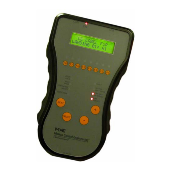
Motion Control Engineering 2000 Manual (294 pages)
Hydraulic Controller
Brand:
Motion Control Engineering
| Category:
Controller
| Size: 5 MB
Table of Contents
Safety Precautions
4
Environmental Considerations
5
Air Conditioned Equipment Cabinets
5
In this Manual
6
Table of Contents
7
Section 1. Motion 2000 TSSA Description
15
General Information
15
Car Controller Description
17
Controller Circuit Boards
19
Landing System
23
LS-QUTE Landing System
23
LS-STAN Landing System
24
LS-EDGE Landing System
25
Operating Mode Descriptions
26
Automatic Operation
26
Mode Entry
26
Inspection Operation
27
Cartop Inspection
27
In Car Inspection
27
Machine Room Inspection
28
Hoistway Access Inspection
28
Attendant Service Operation
29
Mode Entry
29
Independent Service Operation
29
Sabbath Operation
30
Emergency Medical Operation
30
Hospital Service Operation
31
Fire Service Operation
31
Emergency Power Operation
32
Generator Backup
32
EPS Backup
32
Car Recall
32
Capture for Test (Pretest)
33
Test Mode
33
Monitoring and Control Options
34
Imonitor
34
Ireport
34
BMS-Link
35
Motion Portable Adjustment Control (Mpac)
35
Mview
36
Section 2. Installation
37
In this Section
37
Safety Precautions
38
Personal Safety
38
Equipment Safety
38
Installation Considerations
39
Machine Room Preparation
39
Piping and Wiring
40
How Electrical Noise Occurs
40
How to Avoid Electrical Noise Problems
40
Possible EMI/RFI Interference
40
Recommended Tools and Test Equipment
41
Wiring Prints
41
Drawing Number Format
41
Nomenclature
42
Controller Installation
43
Controller Wiring Guidelines
43
General Wiring Guidelines
44
Proper Grounding Procedures
44
Wiring Connections for Properly Grounded Systems
44
Ground Wiring
45
Main AC Power
45
Pump Motor Wiring
45
Low Voltage Signal Wiring
46
Traveling Cable Wiring
46
Section 3. Startup - Inspection Operation
47
In this Section
47
Check for Shorts to Ground
48
Before Applying Power
48
Applying Power
49
Initial Adjustments and Power Phasing
49
Set up for Construction Operation
50
Required Connections
50
Temporary Jumpers
51
Resolving Faults
51
Temporary Run Box Hookup
52
Verifying Proper Starter Operation
53
Hoistway Control Equipment Installation
55
Installing the LS-QUTE Landing System
55
Installing the LS-QUTE Landing System Control Box
55
Installing the Magnetic Strips on LS-QUTE Steel Tape
56
Installing the LS-QUTE Hoistway Limit Switches
56
LS-EDGE Installation
57
LS-EDGE Tape Installation
58
LS-EDGE Top Hanger Assembly
58
LS-EDGE Bottom Hanger Assembly
59
LS-EDGE Broken Tape Switch
60
Hanging the Tape
60
LS-EDGE Sensor Installation
60
LS-EDGE Door Zone Magnets
62
LS-EDGE Terminal Magnets
63
LS-EDGE Terminal Magnet Logic
65
LS-EDGE Electrical Connection
65
Parameter Settings
65
Hoistway Learn Operation
66
Adjusting Floor Heights
66
Initial Stepping Distances
66
Door Position Monitor Switch (if Used)
66
LS-EDGE Short Floors
67
Door Zone Verification
67
Permanently Attach Magnets
67
Complete the Installation and Field Wiring
68
Preparing the Car to Run on Test/Normal Mode
68
Section 4. Final Adjustment
69
In this Section
69
Diagnostic Messages and Input/Output Signals
70
Onboard Diagnostics
70
Absolute Floor Encoding
70
Registering Car Calls
71
Test Mode Operation
72
Running on Test/Normal Mode
73
Final Adjustments on Test Mode
74
Hydraulic Valves
74
Slowdown and Limit Switches
74
Motor Limit Timer
74
Valve Limit Timer
74
Relevel Operation
74
Final Adjustments on Independent Service
75
Door Operator Adjustments
75
Door Open/Close Protection
75
Final Adjustments on Normal Operation
76
Hall Calls
76
Ride and Performance
76
Recheck
76
Options
76
Random Call Testing
76
Remote Governor Testing (Roped Hydro)
77
Static Testing
77
Dynamic Testing
77
Final Testing, LS-EDGE Only
78
Bottom Terminal Test
78
Top Terminal Test
78
Restore Original Settings
78
Release to Normal Operation
79
Section 5. the Computer
81
In this Section
81
The HC-MPU Main Processor Unit
82
Indicators
82
Switches, Buttons & Adjustments
83
Connectors
84
Status Displays
84
Computer Security
85
Password
85
Diagnostic Mode
86
Getting into Diagnostic Mode
86
Function of N Push Button
86
Function of S Push Button
86
Function of + Push Button
86
Format of LCD Display
87
Troubleshooting Using the Computer's Internal Memory
89
Troubleshooting Specific Problems
92
Setting Parameters (Options) to Default Values
93
F1: Program Mode
94
General Description of Program Mode
94
Viewing Menus on the LCD Display
94
Viewing Options Within a Menu
95
Changing a Value
95
Saving the New Values
95
Restoring Original Values
95
Step-By-Step Example
96
Basic Feature Menu Options
97
Fire Service Menu Options
100
Door Operation Menu Options
102
Timer Menu Options
106
Gongs/Lanterns Menu Options
108
Spare Inputs Menu Options
109
Viewing and Assigning Spare Inputs
109
Spare Outputs Menu Options
119
Viewing and Assigning Spare Outputs
119
Extra Features Menu Options
128
UIO Board/Security Enforcement/Connection Order
129
Additional Car Options Menu
134
Timed Features
135
F2: External Memory Mode
136
Getting into External Memory Mode
136
Function of N Push Button
136
Function of S Push Button
136
Function of + Push Button
136
Troubleshooting Using External Memory Mode
137
F3: System Mode
140
Building Security Menu
140
Passcode Request Menu
142
Load Weigher Thresholds
143
Adjusting the Load Thresholds
143
Analog Load Weigher Learn Function
144
Controller System Menu
146
F4: Messages and Floor Labels
147
F5: Controller Utilities/Monitoring and Reporting
149
Controller Utilities Menu
149
Registering Front or Rear Car Calls
149
Date/Time
150
View Event Log
151
Clear Event Log
152
CTL Diagnostic Menu
152
EDG Diagnostics
153
CTL a Diagnostics
158
CTL B Diagnostics
168
System CAN Bus
177
Monitoring and Reporting Menu
178
Diagnostics, Refresh, Reset
178
F6: Hoistway Learn Operations
180
LS-EDGE Steel Tape
180
Adjusting Floor Heights
180
F7: Parameters Adjust
181
Changing Parameters
181
Filling Parameters
181
Using ID Numbers for Direct Parameter Access
182
Parameters
184
F8: Status Displays
186
F1 & F8: Board Software Versions
187
Duplexing
188
Dispatching Algorithm
188
Hardware Connections
188
Troubleshooting
188
Power Phasing
188
In this Section
189
In this Section
190
Section 6. Troubleshooting
190
Troubleshooting Tools
190
Status and Error Messages
191
PC Board Quick References
225
HC-CHP CAN Hub and Power Supply Board
226
SW1 DIP Switch Settings
227
HC-CTL Control Board
228
HC-CTL-2 Terminal Definitions
229
HC-CTL-2 Board LED Indicators
232
HC-CTL-2 Board Jumpers, Fuses, Testpoints, and Switches
233
HC-DVR Driver Board
235
HC-MPU Main Processor Board
238
HC-MPU Battery
240
HC-UIO-2 Universal Input/Output Board
241
Switches
243
Jumpers
243
Test Points
243
Indicators
243
Terminals
243
HC-UIO-2 Switches 7, 8 and 9 Settings
244
HC-UIO-2 Used for Calls
244
Hospital Emergency Operation I/O
244
Troubleshooting
245
Call Inputs and Outputs
246
Spare Inputs and Outputs
247
ICE-COP-2 Car Panel Interface Board
248
Installation Instructions
248
ICE-COP-2 Board Details
249
Normal Operation
249
MC-CPI Car Panel Interface Board
252
Installation Instructions
252
MC-CPI Board Details
254
Before Applying Power
256
MC-LSI Landing System Interface Board
257
LSI Connections
257
SC-3HN Three Input Serial Hall Call Node Board
258
Call Bus Conditions
258
General Installation
258
Addressing and CAN Bus Termination
260
Riser Assignment
260
Floor Number and Front or Rear Opening
260
Baud Rate
260
CAN Bus Termination
260
On Board Diagnostics
261
On Led
261
(Flt) Fault Led
261
Using the MLT / VLT Data Trap
262
Section 7. Appendix
265
In this Section
265
Motion 2000 Parameter Settings Record
266
Program Mode (F1) Parameter Settings Record
267
F7 Parameter Settings Record
274
Elevator Security Information and Operation
276
Security Codes
277
LS-QUTE Landing System Assembly Drawings
278
Factory I/O Assignment, ICE-COP-2 Boards
280
Board #1 - ID: 0
280
Board #2 - ID: 1
280
COP-2 Board #3 - ID: 2
281
COP-2 Board #5 - ID: 5
282
Advertisement
Advertisement
Related Products
Motion Control Engineering Motion 4000
Motion Control Engineering Categories
Control Unit
Controller
Power Supply
More Motion Control Engineering Manuals
Login
Sign In
OR
Sign in with Facebook
Sign in with Google
Upload manual
Upload from disk
Upload from URL