Sign In
Upload
Manuals
Brands
MKS Manuals
Controller
651C
MKS 651C Manuals
Manuals and User Guides for MKS 651C. We have
1
MKS 651C manual available for free PDF download: Instruction Manual
MKS 651C Instruction Manual (172 pages)
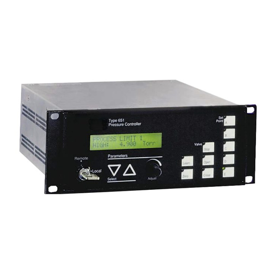
Pressure controller
Brand:
MKS
| Category:
Controller
| Size: 0 MB
Table of Contents
Table of Contents
5
Safety Information
15
Symbols Used in this Instruction Manual
15
Symbols Found on the Unit
16
Table 1: Definition of Symbols Found on the Unit
16
Safety Procedures and Precautions
17
Sicherheitshinweise
19
In dieser Betriebsanleitung Vorkommende Symbole
19
Am Gerät Angebrachte Symbole
20
Tabelle 2: Definitionen der am Gerät Angebrachten Symbole
20
Sicherheitsvorschriften und Vorsichtsmaßnahmen
21
Informations Relatives À la Sécurité
23
Symboles Utilisés Dans Ce Manuel D'utilisation
23
Symboles Apparaissant Sur L'appareil
24
Mesures de Sécurité Et Mises en Garde
25
Información sobre Seguridad
27
Símbolos Usados en el Manual de Instrucciones
27
Símbolos que Aparecen en la Unidad
28
Procedimientos y Precauciones de Seguridad
29
Chapter One: General Information
31
Introduction
31
How this Manual Is Organized
32
Customer Support
33
Chapter Two: Installation
35
How to Unpack the Type 651 Unit
35
Unpacking Checklist
35
Product Location and Requirements
36
Operating Environmental Requirements
36
Safety Conditions
36
Setup
37
Environmental Requirements
37
Checking the Fuses and Line Voltage Selector Switch
38
Table 5: Fuse Information
38
How to Change the Line Voltage
39
Figure 1: Voltage and Fuse Data for the Low Power Unit
39
Figure 2: Voltage and Fuse Data for the High Power Unit
40
Chapter Three: Overview
41
Front Panel
41
Front Panel Components
41
Figure 3: Front Panel of the 651 Instrument
41
Front Panel Display
42
Table 6: Summary of Front Panel Components
42
Local and Remote Operation
43
Command Priority
43
Control Mode: Self-Tuning or PID Control
43
Softstart Control
44
Battery Backups
44
Rear Panel
45
Rear Panel Components
45
Figure 4: Rear Panel of the 651 Instrument
45
Table 7: Slot Labels
45
Electrical Connections
46
Table 8: Serial RS-232 Interface Connector Pinout
46
Table 9: RS-232 Serial Communication Cables
47
Table 10: I/O Connector Pinout
48
Table 11: Transducer Connector Pinout
50
Table 12: System Interface Cables for MKS Transducers
50
Table 13: Valve Connector Pinout
51
Table 14: System Interface Cables for MKS Throttle Valves
51
Labels
52
Serial Number Label
52
Figure 5: Serial Number Label
52
Chapter Four: System Setup
53
Overview
53
RS-232 Commands and Requests
53
Valve Selection and Calibration
54
Setup Menu
55
Control Mode
55
RS-232 Communications
56
Sensor Setup
57
Analog Set Point
59
Valve Position Output
59
Set Points a through E, Pressure/Position Selection
60
Softstart Rates
61
Valve Control
62
Chapter Five: Local Operation
63
Overview
63
How to View and Adjust Set Points
64
How to Activate Set Points
65
How to Identify an Out-Of-Range Condition
65
How to Control the Valve
66
How to Open the Valve
66
How to Close the Valve
66
How to Halt the Valve
66
How to Activate the Learn Function
67
How to Stop the Learn Function
67
How to Zero a Sensor
68
How to Use Special Zero
68
How to Remove Zero
68
How to Set a Process Limit Relay
69
How to View and Adjust a Process Limit Relay
69
How to Disable a Process Limit Relay
69
How to View and Adjust the Analog Set Point
70
How to Zero the Analog Set Point
70
How to Calibrate Full Scale Span for the Analog Set Point
71
How to Set Lead and Gain Parameters
72
How to Calibrate Span of the A/D Converter
73
Chapter Six: Remote Operation
75
Overview
75
RS-232 Commands and Requests
75
Message Syntax
75
Priority of Command Execution
77
How to Change Valve Selection and Calibration
78
How to Determine and Change the Control Mode
79
How to Configure the Sensor Parameters
80
How to Change the Sensor Type
80
How to Change the Sensor Full Scale Voltage
80
How to Change the Sensor Range
81
Table 15: Sensor Range Values
81
How to Request the Pressure Reading
82
Converting Pressure Readings to Absolute Pressure Values
82
How to Zero a Sensor
83
How to Use the Special Zero
83
How to Remove the Zero
83
How to Activate the Learn Function
84
How to Stop the Learn Function
85
How to Determine the Active Set Point
86
How to Select the Active Set Point
87
How to Select Pressure or Position Control
88
How to Change the Set Point Value
89
How to Adjust the Analog Set Point Value
90
How to Set the Analog Set Point Full Scale Range
90
How to Zero the Analog Set Point
91
How to Learn Analog Set Point Full Scale
91
How to Set the Full Scale Level of the Analog Set Point
92
How to Calibrate Span of the A/D Converter
93
How to Respond to a Checksum Error
94
How to Set the Lead and Gain Parameters
95
How to Set the Softstart Control Rate
97
How to Set the Softstart Rate
97
How to Use the Softstart Rate
97
How to Check the Softstart Rate
98
How to Configure the Valve Parameters
99
How to Check the Valve Selected
99
How to Change and Calibrate the Valve
99
How to Change the Valve Position Output
100
How to Change the Valve Control Direction
100
How to Control the Valve
101
How to Open the Valve
101
How to Close the Valve
101
How to Halt the Valve
101
How to Set a Process Limit Relay
102
How to View and Adjust a Process Limit Relay
102
How to Disable a Process Limit Relay
102
How to Check the System Status
103
How to Check the Firmware Version
103
Digital Logic Control
104
I/O Board Digital Circuitry
104
Figure 6: I/O Board Digital Input Circuitry
104
Figure 7: I/O Board Digital Output Circuitry
105
Digital Input Priorities
106
Table 16: Priority of Digital Inputs
106
Digital Functions
107
Table 17: Digital Input Functions
107
Analog Set Point Inputs
109
Table 18: Digital Output Functions
109
Chapter Seven: Battery-Backed Memory Module
111
Replacing the Battery-Backed Memory Module
111
Opening the Unit
111
Removing the CPU Board and Memory Module
112
Figure 8: Location of the Battery-Backed RAM Module
112
Installing a New Memory Module and Replacing the CPU Board
113
Replacing the Cover
113
Chapter Eight: Valve Failsafe Battery Back-Up Option
115
General Information
115
Battery Voltage
116
Valve Positions
116
Startup
117
Threshold Voltage Check
117
Battery Voltage Within Range
117
Figure 9: Initial Display Screen
117
Figure 10: Default Pressure and Position Screen
117
Battery Voltage Out-Of-Range
118
Figure 11: Battery Voltage Low Message
118
Figure 12: Battery Voltage High Message
118
Operation
119
How to Check the Battery Voltage
119
How to Set the Battery Back-Up Valve Control
120
Expected Battery Life
122
Battery Storage
122
Table 19: Expected Battery Life
122
Table 20: Capacity Loss of Stored Battery
122
Battery Replacement
123
Opening the Unit
123
Installing the New Battery
124
Chapter Nine: Maintenance
125
General Information
125
How to Replace Fuses
125
Figure 13: Fuse Holder
126
Appendix A: Product Specifications
127
Appendix B: Model Code Explanation
129
Model Code
129
Appendix C: Product Compatibility
131
Product Compatibility
131
Valves
131
Transducers
131
Table 21: Transducer Current Available from Low and High Power Units
131
Adapter Cables
132
Table 22: 651 Adapter Cables
132
Appendix D: Type 651 Displayless Unit
133
Type 651 Displayless Unit
133
Figure 14: Front Panel of the 651 Displayless Unit
133
RS-232 Configuration
134
Internal Switches
134
Opening/Closing the 651 Controller
134
Figure 15: Dipswitch Bank Location (Top View)
135
Figure 16: Example of Dipswitch Bank
135
Dipswitch Bank Settings
136
Table 23: Default Dipswitch Settings
136
Table 24: I/O Board Dipswitch Bank and RS-232 Communications Settings
137
Appendix E: Initial Settings
139
Table 25: Initial Settings
139
Appendix F: Command and Request Reference
141
Command Reference
141
Table 26: RS-232 Command Summary
142
Request and Response Reference
148
Table 27: RS-232 Request and Response Summary
148
Index
155
Advertisement
Advertisement
Related Products
MKS 651D Series
MKS 653B
MKS 649B
MKS 640A/641A
MKS 647C
MKS 647B
MKS 649A
MKS 640B
MKS 641B
MKS 640A
MKS Categories
Controller
Measuring Instruments
Transducer
Control Unit
Industrial Equipment
More MKS Manuals
Login
Sign In
OR
Sign in with Facebook
Sign in with Google
Upload manual
Upload from disk
Upload from URL