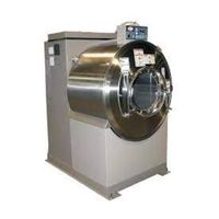
Sign In
Upload
Manuals
Brands
Milnor Manuals
Washer
36026V5J, 36026V7J
Milnor 36026V5J, 36026V7J Extractor Manuals
Manuals and User Guides for Milnor 36026V5J, 36026V7J Extractor. We have
5
Milnor 36026V5J, 36026V7J Extractor manuals available for free PDF download: Service, Service Manual, Mechanical Parts And Service, Installation Manual, Safety Manual
Milnor 36026V5J, 36026V7J Service (119 pages)
Brand:
Milnor
| Category:
Washer
| Size: 9.72 MB
Table of Contents
Table of Contents
3
Page Description
4
How to Order Parts
7
General Safety Requirements
8
Safety-Rigid Washer Extractors
8
Safety Alert Messages
9
Damage and Malfunction Hazards
11
Careless Use Hazards
12
Guards and Covers View
13
Parts List — Guards & Covers
15
About the Forces Transmitted by Milnor Washer-Extractors
18
Rigid Machines
18
Flexibly-Mounted Machines
18
How Strong and Rigid
18
Warranty
18
How Rotating Forces Act on the Foundation
19
Glossary of Tag Illustrations
20
Avoiding Damage from Allied Remote Chemical Delivery Systems
25
Pumped Chemical Inlets on CBW Batch Washer
25
Ensure the System Cannot Siphon
26
Ensure the Chemical Lines Cannot Dribble
27
Siphoning from the Chemical Tank into the Machine
27
Design and Installation Recommendations
28
Dribbling from Chemical Supply Line into Machine
28
Locating a Pumped Chemical System with Positive Closure
29
Guarding against Leaks
29
Safety Placard Use and Placement
30
Parts List — Safety Placard Placement
31
Safety Placard Use and Placement ISO
32
Section 1: Service and Maintenance
39
Preventive Maintenance
40
Lubrication Guidelines
40
Main Bearing Maintenance
40
Lubrication Precautions
40
Preventive Maintenance Schedule
42
Correcting Belt Slippage
42
Baldor Motor Maintenance
42
Maintenance Points
44
Aligning 36 and 42Vxx Motor Mount Plate with the Drive Pulley
46
Fastener Torque Requirements
48
Fasteners and Threadlocker
48
Applying Threadlocker
49
Bolts and Nuts
49
Blind Holes
49
Removing Fasteners
50
Carbon Steel Fasteners
50
Other Fastener Torque Specifications
65
General Maintenance
67
How to Determine Lubrication Interval
68
Type of Grease
70
Correct Grease Gun Procedures
70
Lubrication Procedure
70
Section 2: Drive Assemblies
71
Drive Chart View and Parts List
72
Motor Mount View
75
Parts List — Motor Mount
76
Section 3: Bearing Assemblies
77
Main Bearing, Shell, Cylinder Installation Diagram
78
Main Bearing Assembly Parts List
79
Main Bearing Assembly View
80
Parts List — Bearing Assembly
81
Section 4: Shell and Door Assemblies
87
Shellfront Assembly, Conduit and Interlock View
88
Shellfront Assembly, Conduit and Interlock Parts List
89
Door Assembly View
90
Door Assembly Parts List
91
Interlock Assembly
92
Interlock Assembly Parts List
93
Page Description
95
Section 5: Control and Sensing
95
Vibration Safety Switch Adjustments
96
Effect of Tripping Vibration Safety Switch
96
Vibration Safety Switch View and Parts List
98
Level Sensing
99
Level Sensing
100
Section 6: Chemical and Supply Devices
101
Soap Chute Assembly View
102
Peristaltic Supply Assembly View
103
Peristaltic Supply Assembly Parts List
104
Compartment Supply View
105
Compartment Supply Parts List
106
Flushing Manifold - 5 Compartment Supply View
107
Flushing Manifold Parts List
108
Section 7: Water Piping Assemblies
109
Schematic Symbols Key
110
Water Schematic
111
Water Inlet Assembly View
112
Steam Inlet Assembly View
113
Steam Inlet Assembly Parts List
114
Drain Valve Installation View
115
Drain Valve Installation Parts List
116
3" Electric Drain Valve View
117
3" Electric Drain Valve Parts List
118
Advertisement
Milnor 36026V5J, 36026V7J Mechanical Parts And Service (116 pages)
Brand:
Milnor
| Category:
Laundry Appliance
| Size: 8.61 MB
Table of Contents
Table of Contents
3
36021V5J, V5Z, V7Z; 36026V5J, V5Z, V7Z; 42026V5J, V6Z
6
General Service & Safety-Related Components
7
Limited Standard Warranty
8
How to Get the Necessary Repair Components
9
Trademarks
9
Safety - Rigid Washer Extractors
10
Safety Alert Messages-Internal Electrical and Mechanical Hazards
10
Safety Alert Messages-Cylinder and Processing Hazards
10
Table 1 Trademarks
10
Safety Alert Messages-Unsafe Conditions
12
Damage and Malfunction Hazards
12
Hazards Resulting from Inoperative Safety Devices
12
Hazards Resulting from Damaged Mechanical Devices
12
Careless Use Hazards
13
Careless Operation Hazards-Vital Information for Operator Personnel (See also Operator Hazards Throughout Manual)
13
Careless Servicing Hazards-Vital Information for Service Personnel (See also Service Hazards Throughout Manuals)
13
Safety Placard Use and Placement 36021CPE, NSP, V5J, V5Z and 36026V5J, V5Z
16
36021CPE, NSP, V5J, V5Z and 36026V5J, V5Z
18
36021V7J, V7Z; 36026V7J/W, V7Z; 42026V5J; 42026V6J/W, V7Z; 42030V6J, V6Z
20
Safety Placard Use and Placement-ISO
22
36021V7J, V7Z; 36026V7J/W, V7Z; 42026V5J; 42026V6J/W, V6Z; 42030V6J, V6Z
22
Guards & Covers 36021V5Z, 36026V5Z
24
Guards & Covers 36021V7Z, 36026V7Z, 42026V5J, 42026V6Z, 42030V6Z
26
Figure 1 Front Covers
26
Figure 2 Rear Covers and Side Gasket
27
Torque Requirements for Fasteners
28
Torque Values
28
Fasteners Made of Carbon Steel
28
Without a Threadlocker
28
Figure
28
Table 8 Torque Values for Standard Fasteners with Maximum 5/16-Inch Diameters and no Lubricant
28
Table 9 Torque Values for Standard Fasteners Larger than 5/16-Inch Diameters and no Lubricant
29
Table 10 Torque Values for Plated Fasteners with Maximum 5/16-Inch Diameters and no Lubricant
29
With a Threadlocker
30
Table 11 Torque Values for Plated Fasteners Larger than 5/16-Inch Diameters and no Lubricant
30
Stainless Steel Fasteners
32
Preparation
33
How to Apply a Threadlocker
34
Blind Holes
34
Through Holes
34
Figure 4 Apply Threadlocker in a Blind Hole
34
Figure 5 Apply Threadlocker in a through Hole
35
Drive Assemblies
36
Drive Chart 36021V5J, 36021V5Z, 36026V5J, 36021V5Z
38
Drive Chart 36021V7J, 36021V7Z, 36026V7J, 36026V7Z
40
Drive Chart 42026V5J, 42026V6J, 42026V6Z, 42030V6J, 42030V6Z
42
Drive Pulley and Belt Maintenance
44
Pulley Requirements
44
Condition of Grooves on Pulleys
44
Pulley and Shaft Position
45
Keep Run-Out in Tolerance
46
Belt Requirements
47
Condition of Belts
47
Tension of Belts
48
The Pulleys Must Stay Aligned When You Adjust the Belt Tension
49
How to Do Maintenance on Pulleys and Belts
50
Typical Steps to Replace Pulleys and Belts
50
Run-Out
50
Examples of Procedures Used at the Milnor Factory to Align
51
Pulleys
51
Motor Mount 30015, 30022, 36021, 36026, 42026, & 42030Vxx,Txx
53
Bearing Assembly 36021V5J, 36021V5Z, 36026V5J, 36026V5Z with Starplate
56
Bearing Assembly 36021V7Z, 36026V7Z, 42026V5J, 42026V6Z, 42030V6Z
59
Cylinder & Shell
63
Main Bearing, Shell, Cylinder Installation
64
36021V5J, 36021V5Z, 36026V5J, 36026V5Z with Starplate
64
36021V7Z, 36026V7Z, 42026V5J, 42026V6Z, 42030V6Z
69
Cross Section of Shell, Cylinder, Bearing, and Frame
69
Main Bearing, Shell, and Cylinder Installation
70
20 Inch Door Assemblies after 8/2016
73
42030V6Z
74
Mcr12; Mct16/18/27; Mwf18/27; Mwr27/36; Mwt12/16/18/27; 3015/3022T6X, Vrj, V8Z, Vzz; 3022X8R; 36021V5J, V5Z, V7Z; 36026V5J, V5Z, V7Z
78
42026V5J, V6Z. 42030V6Z
78
Door Lock Mechanisms
79
Door Handle and Lock Actuator
81
Door Handle and Lock Actuator
82
Chemical Supply Devices
84
42030V6Z
88
Soap Chute 36021V5J, V5Z, V7Z; 36026V5J, V5Z, V7Z; 42026V5J, V6Z; 42030V6Z
88
42030V6Z
90
Supply Chute
90
Valve Manifold
91
Water & Steam
94
Water Schematic 36021V5J, V5Z, V7Z; 36026V5J, V5Z, V7Z; 42026V5J, V6Z; 42030V6Z
96
42030V6Z
98
Steam Inlet 36021V5J, V5Z, V7Z; 36026V5J, V5Z, V7Z; 42026V5J, V6Z; 42030V6Z
104
Drain Valve 36021V5J, V5Z, V7Z; 36026V5J, V5Z, V7Z; 42026V5J, V6Z; 42030V6Z
106
Inch Electrical Drain Valve
108
Control & Sensing
110
42030V6Z
111
36021V5J, V5Z, V7Z; 36026V5J, V5Z, V7Z; 42026V5J, V6Z; 42030V6Z
112
Vibration Safety Switch Adjustments
114
What the Vibration Safety Switch Does
114
Adjustments
114
Vibration Safety Switch
116
Milnor 36026V5J, 36026V7J Installation Manual (56 pages)
Brand:
Milnor
| Category:
Washer
| Size: 9.62 MB
Table of Contents
Table of Contents
3
General Information
6
Limited Standard Warranty
7
How to Get the Necessary Repair Components
8
Trademarks
8
Safety - Rigid Washer Extractors
9
Safety Alert Messages-Internal Electrical and Mechanical Hazards
9
Safety Alert Messages-Cylinder and Processing Hazards
9
Safety Alert Messages-Unsafe Conditions
10
Damage and Malfunction Hazards
10
Hazards Resulting from Inoperative Safety Devices
10
Hazards Resulting from Damaged Mechanical Devices
11
Careless Use Hazards
12
Careless Operation Hazards-Vital Information for Operator Personnel (See also Operator Hazards Throughout Manual)
12
Careless Servicing Hazards-Vital Information for Service Personnel
12
(See also Service Hazards Throughout Manuals)
12
Installation Tag Guidelines
13
Important Installation Precautions
16
External Fuse/Breaker, Wiring, and Disconnect Requirements
16
Fuse or Circuit Breaker Size
16
If a Fuse Is Used
16
If a Standard Circuit Breaker Is Used
16
If an Inverse Time Circuit Breaker Is Used
16
Wire Size
16
Ground
17
Disconnect Switch for Lockout/Tagout
17
Using GFCI (Ground Fault Circuit Interrupter) Device
17
Machines
17
Disclaimer of Responsibility
18
Major Design Considerations
18
Primary Information Sources
19
Prevent Damage from Chemical Supplies and Chemical Systems
19
Figure 1 How Rotating Forces Act on the Foundation
19
How Chemical Supplies Can Cause Damage
20
Dangerous Chemical Supplies and Wash Formulas
20
Incorrect Configuration or Connection of Equipment
20
Figure 2 Incorrect Configurations that Let the Chemical Supply Go in the Ma
21
Equipment and Procedures that Can Prevent Damage
22
Use the Chemical Manifold Supplied
22
Figure 3 Incorrect Configurations that Let the Chemical Supply Go in the Ma
22
Figure 4 Examples of Manifolds for Chemical Tubes. Your Equipment Can Look
22
Close the Line
23
Do Not Let a Vacuum Occur
23
Flush the Chemical Tube with Water
23
Put the Chemical Tube Fully below the Inlet
23
Prevent Leaks
23
Figure 5 a Configuration that Prevents Flow in the Machine When the Pump Is off (if the Chemical Tube and Tank Have no Pressure)
23
Installation Procedures
24
Handling a Washer-Extractor from Delivery to Final Location
24
Notices
24
Qualified Personnel Only
24
Disclaimer
24
Other Tasks
24
Facility Prerequisites
25
Rigger Precautions
25
Technician Precautions
27
Can the Door(S) be Opened before Utilities Are Connected
29
Connection Precautions for Washer-Extractors
29
Notices
30
Machine Must be Anchored
30
Utility Requirements and Related Information
30
Plumber Precautions
31
Electrician Precautions
32
Chemical Supplier Precautions
33
Dimensional Drawings
34
Bd3621V5Jae/2022252 - 36021V5J
35
BD3621V5JAB/2022252 - 36021V5J (Options)
36
Bd3621V5Zbe/2015462 - 36021V5Z
37
BD3621V5ZBB/2020034 - 36021V5Z Options
38
Bd3621V7Zbe/2017134 - 36021V7Z
39
BD3621V7ZBB/2020034 - 36021V7Z Options
40
Bd3626V5Jae/2022252 - 36026V5J
41
BD3626V5JAB/2022252 - 36026V5J (Options)
42
Bd3626V5Zbe/2021103 - 36026V5Z
43
BD3626V5ZBB/2020034 - 36026V5Z Options
44
Bd3626V7Zbe/2017134 - 36026V7Z
45
BD3626V7ZBB/2020034 - 36026V7Z Options
46
Bd4226V5Jae/2022252 - 42026V5J
47
BD4226V5JAB/2022252 - 42026V5J (Options)
48
Bd4226V6Zbe/2022424 - 42026V6Z
49
BD4226V6ZBB/2020034 - 42026V6Z Options
50
Bd4230V6Zbe/2019416 - 42030V6Z
51
BD4230V6ZBB/2020034 - 42030V6Z Options
52
Dimensional Drawings: Pedestals
53
BD36V5BSBE/2013063 - 36021/36026V5J, V5Z (Pedestal)
55
BD42V6BSAE/2013064 - 3621/3626V7J, V7Z; 4226/4230V6J, V6Z (Pedestal)
56
Advertisement
Milnor 36026V5J, 36026V7J Service Manual (117 pages)
Washer-Extractors
Brand:
Milnor
| Category:
Washer
| Size: 7.47 MB
Table of Contents
Table of Contents
4
73 5. 20 Inch Door Assemblies after 8/2016
77
20" Flat Front Door
78
Door Lock Mechanism
81
Door Handle and Lock Actuator
84
83 6. Chemical and Supply Devices
87
Peristaltic Supply Assembly
89
Water Piping Assemblies
97
Water Schematic
99
Water Inlet Assemblies
101
Steam Inlet Assembly
106
Drain Valve Installation
108
Inch Electric Drain Valve
109
Control and Sensing Assemblies
111
Vibration Safety Switch Adjustments
112
Temperature Probe
115
Level Sensing
116
Milnor 36026V5J, 36026V7J Safety Manual (37 pages)
Milnor Rigid Washer Extractors Safety Guide
Brand:
Milnor
| Category:
Washer
| Size: 1.48 MB
Table of Contents
English
8
Table of Contents
8
1 General Safety Requirements-Vital Information for Management Personnel
9
Laundry Facility
9
Personnel
10
Safety Devices
10
Maintenance
11
2 The Safety Placards and Their Messages-Vital Information for All Personnel
12
Service Preparations and Entering the Machine
13
Electrical and Mechanical Parts
14
Linen and the Turning Cylinder
15
Heat
16
Dangerous Materials
17
Español
23
1 General Safety Requirements-Vital Information for Management Personnel
24
Safety Devices
27
Maintenance
28
2 The Safety Placards and Their Messages-Vital
30
Service Preparations and Entering the Machine
31
Electrical and Mechanical Parts
33
Linen and the Turning Cylinder
35
Heat
36
Dangerous Materials
37
Advertisement
Related Products
Milnor 36026V7J
Milnor 36026V7J/V7W
Milnor 36026X8W
Milnor 36026X8J
Milnor 36026X8R
Milnor 36026V7W
Milnor 36026V5Z
Milnor 36026V7Z
Milnor 36026
Milnor 36026V Series
Milnor Categories
Washer
Industrial Equipment
Controller
Laundry Appliance
Dryer
More Milnor Manuals
Login
Sign In
OR
Sign in with Facebook
Sign in with Google
Upload manual
Upload from disk
Upload from URL