Lenze 8400 motec Hardware Manual
L-force drives.
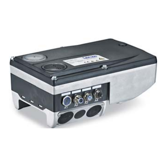
decentralised frequency inverter.
0.37 ... 7.5 kw.
e84dg series
Hide thumbs
Also See for 8400 motec:
- Software manual (376 pages) ,
- Mounting instructions (264 pages) ,
- Hardware manual (172 pages)

Related Manuals for Lenze 8400 motec


Summary of Contents for Lenze 8400 motec
- Page 1 L-force Drives EDS84DG752 .Peb Hardware Manual Translation 8400 motec 0.37 ... 7.5 kW E84DGxxxxxxxxx Decentralised frequency inverter ...
- Page 2 0Fig. 0Tab. 0...
-
Page 3: Table Of Contents
............General safety and application notes for Lenze controllers . - Page 4 ........Installation of 8400 motec pre-assembled on the motor .
- Page 5 Contents Overview of the commissioning steps with keypad ......6.4.1 Keypad control ..........6.4.2 Short overview of the parameters for quick commissioning .
- Page 6 Contents Communication modules ..........9.5.1 CANopen .
-
Page 7: About This Documentation
This Hardware Manual is intended for all persons who design, install, commission, and adjust controllers of the 8400 Inverter Drives product range. Tip! Information and tools concerning the Lenze products can be found in the download area under www.lenze.com ... -
Page 8: Document History
About this documentation Document history Document history Material number Version Description 12/2014 TD15 UL notes in French for Canada .Peb EAC Conformity General corrections 13410318 06/2012 TD15 General revision, supplements, and corrections 13394702 11/2011 TD15 Extension 4 ... 7.5 kW 13375479 04/2011 TD15... -
Page 9: Conventions Used
About this documentation Conventions used Conventions used This documentation uses the following conventions to distinguish between different types of information: Spelling of numbers Decimal separator Point In general, the decimal point is used. For instance: 1234.56 Warnings UL warnings Given in English and French UR warnings ... -
Page 10: Terms And Abbreviations Used
power terminals Drive unit 8400 motec controller Communication unit Optional interfaces per I/O, fieldbus, safety system Wiring unit Ready-made motor connection, replaces the motor terminal box Abbreviation... -
Page 11: Notes Used
About this documentation Notes used Notes used The following pictographs and signal words are used in this documentation to indicate dangers and important information: Safety instructions Structure of safety instructions: Danger! (characterises the type and severity of danger) Note (describes the danger and gives information about how to prevent dangerous situations) Pictograph and signal word... -
Page 12: Safety Instructions
– The procedural notes and circuit details described in this documentation are only proposals. It’s up to the user to check whether they can be transferred to the particular applications. Lenze Drives GmbH does not accept any liability for the suitability of the procedures and circuit proposals described. - Page 13 EMC legislation. Lenze controllers may cause a DC current in the PE conductor. If a residual current device is used as a protective means in the case of direct or indirect contact with a three-phase controller, a residual current device of type B must be used on the current supply side of the controller.
- Page 14 Safety instructions General safety and application notes for Lenze controllers Operation If necessary, systems including controllers must be equipped with additional monitoring and protection devices according to the valid safety regulations (e.g. law on technical equipment, regulations for the prevention of accidents). The controllers can be adapted to your application.
-
Page 15: General Safety And Application Instructions For Lenze Motors
Safety instructions General safety and application instructions for Lenze motors General safety and application instructions for Lenze motors (According to: Low-Voltage Directive 2006/95/EC) General Low-voltage machines have hazardous live and rotating parts and possibly also hot surfaces. Synchronous machines induce voltages at open terminals during operation. - Page 16 Safety instructions General safety and application instructions for Lenze motors Installation Ensure an even surface, solid foot and flange mounting and exact alignment if a direct clutch is connected. Avoid resonances with the rotational frequency and double mains frequency which may be caused by the assembly. Turn rotor by hand, listen for unusual slipping noises.
- Page 17 Safety instructions General safety and application instructions for Lenze motors Commissioning and operation Before commissioning after longer storage periods, measure the insulation resistance. In case of values 1 k per volt of rated voltage, dry winding. For trial run without output elements, lock the featherkey. Do not deactivate the protective devices, not even in a trial run.
-
Page 18: Residual Hazards
Safety instructions Residual hazards Residual hazards Protection of persons Switch off mains voltage before removing the controller (Drive Unit). ƒ Before working on the controller, check if no voltage is applied to the power ƒ terminals because – depending on the device - the power terminals U, V, W, Rb1, Rb2, T1 and T2 remain live for at least 3 minutes after disconnecting the mains. -
Page 19: Product Description
Product description System overview Product description System overview Overview of possible components of the 8400 motec system. < > E84GDC010 Drive Unit (decentralised 8400 motec frequency inverter) Communication Unit (fieldbus interfaces) Wiring Unit (motor connection adapter) Gearbox/geared motors ... -
Page 20: Device Features
Product description Device features Device features General features Compact motor inverter ƒ Modular design ƒ Part of the Inverter Drives 8400 product family ƒ – Identical product features – Identical operation Scalable fieldbus communication (optional) ƒ On site diagnostics per status LEDs ƒ... -
Page 21: Identification
Product description Identification Identification Due to the modular design of the 8400 motec controllers, every unit has an own nameplate. The nameplate shows the type designation of the respective unit. The type designation serves to exactly identify a unit. ... -
Page 22: Type Code
Due to the modular structure of the 8400 motec controller, every unit needs an own type key. Though, a type key is also defined for the 8400 motec controller as a set, it cannot be attached visibly to the set or single units due to practical and logistical reasons. - Page 23 Product description Type code The type codes Communication Unit E84DGFC Module part Communication Unit - 8400 motec Communication (fieldbus) N = NO BUS (without fieldbus) A = AS-i C = CANopen G = EtherNet/IP P = PROFIBUS R = PROFINET...
- Page 24 Product description Type code The type codes 8400 motec Set E84DV Product range Inverter Drives 8400 motec Version B = not relevant Design M = motor-mounted device W = wall-mounted device Power e.g. 152 = 15 x 10 W = 1.5 kW...
-
Page 25: Overview Of Control Terminals
Product description Overview of control terminals Overview of control terminals The control terminals of the 8400 motec controllers are available in the entire system in two versions: Extended or ƒ Standard. ƒ The control terminals are always located in the Communication Unit. -
Page 26: Technical Data
Technical data General data and operating conditions Technical data General data and operating conditions Conformity and approval Conformity 2006/95/EC LowVoltage Directive On safety of low voltage Eurasian Conformity equipment (TR CU 004/2011) TR CU: Technical Regulation of Customs Union Electromagnetic Eurasian Conformity ... - Page 27 Technical data General data and operating conditions Protection of persons and equipment Enclosure EN 60529 IP65 in ready-for-use state: optional: IP66 Close unused bores for cable glands with blanking plugs! Close unused connectors with NEMA 250 Protection according to ...
- Page 28 Motors EN 60034 Only use motors suitable for inverter operation. Insulation resistance: at least û 1.5 kV, at least du/dt 5 kV/s Length of the motor < 20 m (Lenze system cable, shielded) cable Ambient conditions Climatic Storage IEC/EN 60721-3-1 1K3 (-30 ...
- Page 29 Category C2 Wall mounting EN 61800-3 E84DVBW3714 ... 7524 Category C2 for switching frequency 4 kHz and with Lenze system cable 20 m E84DVBW3714 ... 7524 for Category C2 switching frequency 8 kHz and with Lenze system cable ...
- Page 30 Technical data General data and operating conditions Control Control modes VFCplus: V/f control (linear or square-law) SLVC: Sensorless vector control (speed) VFCplus eco: Energy-efficient V/f control Switching frequency 4 kHz, 8 kHz, 16 kHz, Torque behaviour Maximum torque 1.5 x M for 60 s if rated motor power = rated controller power...
-
Page 31: Rated Data
Technical data Rated data Overview Rated data 4.2.1 Overview Input data Basis of the data Mains Voltage Voltage range Frequency range f [Hz] Lrated Lrated 3/PE AC 320 - 0 % ... 440 + 0 % 45 - 0 % ... 65 + 0 % 3/PE AC 432 - 0 % ... - Page 32 Technical data Rated data Overview Power losses Power loss P Type when operating with rated output current I when controller is inhibited arated E84DGDVB3714 E84DGDVB5514 E84DGDVB7514 E84DGDVB1124 E84DGDVB1524 E84DGDVB2224 E84DGDVB3024 E84DGDVB4024 E84DGDVB5524 E84DGDVB7524 EDS84DG752 EN 5.0...
-
Page 33: Operation At Rated Mains Voltage 400 V
Technical data Rated data Operation at rated mains voltage 400 V 4.2.2 Operation at rated mains voltage 400 V Basis of the data Mains Voltage Voltage range Frequency range f [Hz] Lrated Lrated 3/PE AC 320 - 0 % ... 440 + 0 % 45 - 0 % ... - Page 34 Technical data Rated data Operation at rated mains voltage 400 V Fuses and cable cross-sections Point-to-point connection - direct wiring of the mains voltage - typical fusing ƒ Operation Type Installation according to EN 60204-1 Installation according to UL L1, L2, L3 - laying system L1, L2, L3 ...
-
Page 35: Operation At Increased Rated Power At 400 V Mains Voltage
Technical data Rated data Operation at increased rated power at 400 V mains voltage 4.2.3 Operation at increased rated power at 400 V mains voltage In continuous operation, the controllers can be actuated with a more powerful motor. The overload capacity is limited to 120 %. Typical applications are pumps with a quadratic load characteristic, or fans. - Page 36 Technical data Rated data Operation at increased rated power at 400 V mains voltage Switching frequency-dependent output currents Output currents [A] at switching frequency 2 kHz 4 kHz 8 kHz 16 kHz Type arated2 arated4 arated8 arated16 aM16 E84DGDVB3714 E84DGDVB5514 E84DGDVB7514 E84DGDVB1124 E84DGDVB1524...
-
Page 37: Operation With Rated Mains Voltage 480 V
Technical data Rated data Operation with rated mains voltage 480 V 4.2.4 Operation with rated mains voltage 480 V Basis of the data Mains Voltage Voltage range Frequency range f [Hz] Lrated Lrated 3/PE AC 432 - 0 % ... 528 + 0 % 45 - 0 % ... - Page 38 Technical data Rated data Operation with rated mains voltage 480 V Fuses and cable cross-sections Point-to-point connection - direct wiring of the mains voltage - typical fusing ƒ Operation Type Installation according to EN 60204-1 Installation according to UL L1, L2, L3 - laying system L1, L2, L3 ...
-
Page 39: Switching Frequency Reduction
Technical data Switching frequency reduction Switching frequency reduction Under certain operating conditions, the maximum output current is limited for all devices: When the maximum heatsink temperature is exceeded, the controller switches ƒ from 16 kHz to 8 kHz and from 8 kHz to 4 kHz, irrespective of the switching frequency mode. -
Page 40: Overcurrent Operation
Overcurrent operation Overcurrent operation If the device utilisation Ixt exceeds the threshold set (C00064/1, Lenze setting = 100 %), the monitoring function triggers an error response and sets the controller to the ”Fault” device status. To exit the device status, the error must be reset (”acknowledged”) explicitly. - Page 41 = 16 kHz Type E84DGDVB3714 E84DGDVB5514 E84DGDVB7514 E84DGDVB1124 E84DGDVB1524 E84DGDVB2224 E84DGDVB3024 E84DGDVB4024 E84DGDVB5524 E84DGDVB7524 Tip! For calculations of application-specific cycles please contact your Lenze contact person. EDS84DG752 EN 5.0...
-
Page 42: Terminal Description
Technical data Terminal description Overview Terminal description 4.5.1 Overview 0.37 ... 3 kW E84DGDV001 WU - Wiring Unit X1/L1, L2, L3 Mains X1/U, V, W Motor X1/Rb1, Rb2 Brake resistor X1/BD1, BD2 Motor holding brake X1/T1, T2 Motor temperature monitoring Protective earth ... - Page 43 Technical data Terminal description Overview 4 ... 7.5 kW E84DGDV087 WU - Wiring Unit X2/U, V, W Motor X2/Rb1, Rb2 Brake resistor X2/BD1, BD2 Motor holding brake X2/T1, T2 Motor temperature monitoring CU - Communication Unit The connection opportunities depend on the communication module option. X4/COM, NO Switching contact, potential-free X4/Ax, GND...
-
Page 44: Power Terminals
Technical data Power terminals Power terminals 0.37 ... 3 kW - X1 E84DG032 Terminal data Conductor cross-section Tightening torque [AWG] [Nm] [lb-in] 1 ... 4 E84DGDVB3714 18 ... 10 3.5 x 0.6 2 x 0.5 ... 2 x 2.5 E84DGDVB1524 1 ... -
Page 45: Mains Connection
Technical data Power terminals Mains connection 4.6.1 Mains connection Pin / name Features Rated value L1, L2, L3 Mains phases according to rated data assigned X1: Earthing, 2 x in the Wu 4.6.2 Motor connection Pin / name Features Rated value U, V, W Motor phases... -
Page 46: Control Terminals
Technical data Control terminals Control terminals E84DG047 E84DG015 AS-i EtherCAT PROFINET EtherNet/IP PROFIBUS 24 V ext. E84DG015 E84DG016 Assignment X4 with CANopen, PROFIBUS, AS interface, PROFINET, EtherNet/IP, EtherCAT without safety (standard) Assignment X4 with CANopen, PROFIBUS, AS interface, PROFINET, EtherNet/IP, EtherCAT with ... - Page 47 Technical data Control terminals Connection options for Communication Unit Plugs Name Fieldbus Safety Digital input/output Analog Relay Holding input brake Type SIA/SIB AI/AU COM/NO BD1/BD2 NO BUS E84DGFCNNNx (without fieldbus) Standard I/O E84DGFCSNNx (without fieldbus) E84DGFCAxNx E84DGFCAxJx...
-
Page 48: Digital Inputs
Technical data Control terminals Digital inputs 4.7.1 Digital inputs Pin / name Features Rated value Controller enable according to IEC 61131-2, type 1 Digital inputs DI1/DI2: Two-track frequency input for HTL encoder 0 ... 10 kHz (parameterisable) DI3 ... DI5 not available for NO BUS Pin / name Features Rated value... - Page 49 Technical data Control terminals Digital inputs PROFINET DI - E84DGFCR9xx M12 female socket A-Coding n. c. EtherCAT® DI - E84DGFCT9xx M12 female socket A-Coding n. c. EtherNet/IP DI - E84DGFCG9xx M12 female socket A-Coding n. c. EDS84DG752 EN 5.0...
-
Page 50: Digital Output
Technical data Control terminals Digital output 4.7.2 Digital output Pin / name Features Rated value Digital output 24 V DC 50 mA 4.7.3 Analog input The analog input is only available with the modules Communication in the ”Advanced” version or ƒ... -
Page 51: Communication Connection
Technical data Control terminals Communication connection 4.7.5 Communication connection 8400 motec enables communication via the fieldbuses CANopen, ƒ PROFIBUS, ƒ AS interface, ƒ EtherNet/IP, ƒ PROFINET and ƒ EtherCat. ƒ The connections of the fieldbuses are always assigned to M12 plugs. The plugs are mounted to the connection positions Ax, depending on the fieldbus. -
Page 52: Dimensions
Technical data Dimensions Standard motor mounting Dimensions 4.8.1 Standard motor mounting E84DG... Dimensions - standard motor mounting [mm] Type m [kg] E84DGDVB371T E84DGDVB551T E84DGDVB751T E84DGDVB112T E84DGDVB152T E84DGDVB222T E84DGDVB302T E84DGDVB402T E84DGDVB552T E84DGDVB752T Reduction possible if no free space for plugs or cables/cable glands is required. For the NO BUS version, without cable glands ... -
Page 53: Wall Mounting
Technical data Dimensions Wall mounting 4.8.2 Wall mounting E84DGMWE1001 Dimensions - wall mounting [mm] Type m [kg] E84DGDVB371T E84DGDVB551T E84DGDVB751T E84DGDVB112T E84DGDVB152T E84DGDVB222T E84DGDVB302T Reduction possible if no free space for plugs or cables/cable glands is required. Arrangement of several devices only to the sides, so that the convection cooling remains ensured. With E84DGVN1E or E84DVBWxxxxxxxxxx1 With E84DGVN2E or E84DVBWxxxxxxxxxx2 E84DG... -
Page 54: Installation
Installation Important notes Installation Important notes Danger! Dangerous electrical voltage All power terminals remain live for up to three minutes after mains disconnection. Possible consequences: Death or severe injuries when touching the power terminals. ƒ Protective measures: Switch off the power supply and wait for at least three minutes before ƒ... - Page 55 Installation Important notes Stop! No device protection if the mains voltage is too high The mains input is not internally fused. Possible consequences: Destruction of the device if the mains voltage is too high. ƒ Protective measures: Observe the maximally permissible mains voltage. ƒ...
- Page 56 Installation Important notes Stop! Overvoltage at components: In case of an earth fault in IT systems, intolerable overvoltages may occur in the plant. Possible consequences: Destruction of the device. Protective measures: Before using the controller in the IT system, remove the contact screws on the supply side and the motor side.
-
Page 57: Safety Instructions For The Installation According To Ul/Csa
Installation Safety instructions for the installation according to UL/CSA Safety instructions for the installation according to UL/CSA Original - English Warnings! These devices are suitable for field wiring. ƒ Intended for use with 75 °C wire. ƒ Intended for use with copper conductors only. ƒ... -
Page 58: Safety Instructions For The Installation According To Ul/Csa
Installation Safety instructions for the installation according to UL/CSA Safety instructions for the installation according to UL/CSA Original - French Avertissement ! Ces équipements sont adaptés à un câblage à pied d’oeuvre. ƒ Utiliser des conducteurs 75 °C. ƒ Utiliser exclusivement des conducteurs en cuivre. -
Page 59: Installation According To Emc (Installation Of A Ce-Typical Drive System)
Installation Installation according to EMC (installation of a CE-typical drive system) Shielding Installation according to EMC (installation of a CE-typical drive system) Design of the cables It is imperative to comply with the regulations concerning minimum cross-sections ƒ of PE conductors. The cross-section of the PE conductor must be at least as large as the cross-section of the power connections. -
Page 60: Motor Cable
– The overlap rate of the braid must be at least 70 % with an overlap angle of 90 °. The cables used must correspond to the requirements at the location (e.g. ƒ EN 60204-1). Use Lenze system cables. ƒ Extensively apply the shielding in the plug and attach it in a way which ensures ƒ... -
Page 61: Control Cables
Installation Installation according to EMC (installation of a CE-typical drive system) Control cables Danger! Uncontrolled motor movements can occur If the motor cable is damaged, a short circuit between the brake control cables and the motor cables can cause motor movements with low torque. Possible consequences: Personnel in the vicinity of the motor can be injured. -
Page 62: Mechanical Installation
Installation Mechanical installation Mechanical installation If the cooling air is polluted (fluff, (conductive) dust, soot, aggressive gases), take ƒ adequate countermeasures, as e.g.: – Regular cleaning of the cooling ribs at the controller – Separate air guide Possible mounting position: ƒ... -
Page 63: Electrical Installation
Installation Electrical installation Power connections Electrical installation 5.6.1 Power connections Principle circuit diagram 0.37 ... 3 kW E84DG... E84DG... X1 BD2 BD1 L1 L3 Rb2 Rb1 U X1 L1/L2/L3 X1 L1/L2/L3 J> 3/PE AC F1 … F3 3/N/PE AC 400 V E84DG040 E84DG034 4 ... -
Page 64: Wiring Of Control Connections
Installation Electrical installation Wiring of control connections 5.6.2 Wiring of control connections Principle circuit diagram X4 - E84DGFCNNNx (NO BUS) 100 mA 24 V ext. E84DG016 X4 - E84DGFCSNNx (Standard I/O) +10 V/ 5 mA 100 mA " 24 V ext. - Page 65 Installation Electrical installation Wiring of control connections X4 - E84DGFCxxNx (AS-i, CAN, PROFIBUS, PROFINET, EtherNet/IP, EtherCAT) AS-i 100 mA EtherCAT PROFINET EtherNet/IP PROFIBUS 24 V ext. 24 V ext. E84DG047 X4 - E84DGFCxxJx (AS-i, CAN, PROFIBUS, PROFINET, EtherNet/IP, EtherCAT & Safety) +10 V/ AS-i 5 mA...
-
Page 66: Installation Of 8400 Motec Pre-Assembled On The Motor
Installation of 8400 motec pre-assembled on the motor Plug at the Wiring Unit Installation of 8400 motec pre-assembled on the motor The worksteps to be done during the installation of pre-assembled 8400 motec controllers depend on the selected connection type of the Wiring Unit: Plugs ƒ... -
Page 67: Attaching The Cable Gland
Installation Installation of 8400 motec pre-assembled on the motor Attaching the cable gland 5.7.2 Attaching the cable gland 0.37 ... 3 kW In order to be able to screw the cable glands in the Wiring Unit and connect the mains cable, you must first dismount the Drive Unit and the Communication Unit as follows: 1. - Page 68 Installation Installation of 8400 motec pre-assembled on the motor Attaching the cable gland 4 ... 7.5 kW In order to be able to screw the cable glands into the Drive Unit and connect the mains cable, you must first dismount the Communication Unit as follows: 1.
-
Page 69: Retrofitting The 8400 Motec Controller
5.8.1 Preparing a motor for the 8400 motec installation In order to install the 8400 motec, you must first remove the terminal box housing. In case of a standard motor, proceed as follows: 1. After loosening the screws, remove the terminal box cover. -
Page 70: Mounting The Wiring Unit
Installation Retrofitting the 8400 motec controller Mounting the Wiring Unit 5.8.2 Mounting the Wiring Unit 0.37 ... 3 kW Before being mounted, the WU can be extended with accessories. If there is sufficient space, accessories can also be mounted subsequently if required. The plug connector in the WU should be removed for easier handling and later wiring. -
Page 71: Mounting Of The Communication Unit
Installation Retrofitting the 8400 motec controller Mounting of the Communication Unit 4 ... 7.5 kW The Wiring Unit is mounted to the Drive Unit by means of the four supplied screws and the seal. In the case of this device size, accessories are mounted to the Drive Unit. If there is sufficient space, it is also possible to mount accessories subsequently. -
Page 72: Settings At The Drive Unit
Installation Retrofitting the 8400 motec controller Settings at the Drive Unit 4 ... 7.5 kW The CU can be extended with accessories before being mounted. Additional cable glands or M12 connectors for further input and output signals can be mounted. - Page 73 Installation Retrofitting the 8400 motec controller Mounting of the Drive Unit 4 ... 7.5 kW The DU has already been mounted with the WU and is completed by attaching the cover to the CU. EDS84DG752 EN 5.0...
-
Page 74: Measures When Drive Is Used In It Systems
Installation Measures when drive is used in IT systems Measures when drive is used in IT systems If the drive is mounted within an IT system, internal filters must be separated from the PE conductor. How to proceed: 1. If the controller has already been mounted: switch off mains voltage! 2. -
Page 75: Wall Mounting Of 8400 Motec Controller
For an installation of the controller conforming to standards, the PE conductor connector can be used for an additional equipotential bonding. The following mounting steps of the 8400 motec motor inverter corresponds to the retrofitting procedure. Additional workstep when the Wiring Unit is wired: Laying and connection of the motor cable, with temperature monitoring if required. -
Page 76: Commissioning
When setting the V/f base frequency (C00015), please observe the following ƒ difference to the 8400 StateLine/HighLine/TopLine controllers: For the 8400 motec drive, the reference voltage for the V/F base frequency is the rated motor voltage (C00090) according to the motor nameplate (independently of the line-side supply voltage). - Page 77 Tip! In the Lenze setting, the ”linear V/f characteristic” operating mode is set as motor control. The parameter settings are preset so that if the frequency inverter and the 50 Hz asynchronous machine match in terms of power, the controller is ready for operation without any further need for parameterisation and the motor operates satisfactorily.
-
Page 78: Quick Commissioning
Commissioning Quick commissioning Quick commissioning Stop! Automatic motor start In ”Local mode” The auto-start option ”Inhibit at power-on” is not set. When the mains is connected, the motor starts if the controller enable RFR is bridged or set. (”Local mode” => DIP1/1 = ON and DIP2/5-7 = OFF) Possible consequences: Danger or damages through unexpected motor start. -
Page 79: General Configuration Settings
Commissioning Quick commissioning General configuration settings 6.2.1 General configuration settings For initial commissioning, settings can be made via DIP switch and potentiometer. The settings must be made before mounting the drive unit since the setting elements cannot be accessed from the outside. Setting elements 0.37 ... - Page 80 Commissioning Quick commissioning General configuration settings Setting elements 4 ... 7.5 kW The setting elements are located on the top of the drive unit. Provide for isolation from supply and secure to prevent a restart. ƒ Remove small cover on the top. ƒ...
- Page 81 Commissioning Quick commissioning General configuration settings Possible settings with DIP1 (Lenze setting bold) DIP1 Switch Description Settings after DIP1, DIP2, P1, P2, and on ( I ) P3 active off ( 0 ) Direction of rotation left right Control quadratic...
- Page 82 Commissioning Quick commissioning General configuration settings Control modes Description DIP2/5-7 (DIx High) The technology application is controlled locally via elements on the controller and the digital input terminals: (local mode) At mains connection the motor starts up automatically if RFR is bridged or set! ...
- Page 83 Commissioning Quick commissioning General configuration settings Possible settings with P2 ”Speed” With P2, a motor speed setpoint in percent of the rated speed in C00011 can be preset in 10 steps (JOG fixed setpoint). The JOG setpoint is only activated if input DI1 is set in ”Local mode”.
- Page 84 Commissioning Quick commissioning General configuration settings Preconditions for initial switch-on The wiring unit is mounted and wired according to the instructions, ƒ – directly on a motor clamping flange or – with the wall adapter on a suitable surface near the motor. Connections with the mains, motor, holding brakes, etc.
-
Page 85: Commissioning Steps
Commissioning Quick commissioning Commissioning steps 6.2.2 Commissioning steps Commissioning Proceed step by step: Switch on the mains ƒ Observe status display ƒ – After a short initialisation time, the display must be blinking green. Deactivate requirements of the safety function ƒ... -
Page 86: Handling Of The Keypad
Commissioning Handling of the keypad Handling of the keypad The keypad X401 serves to quickly and easily set parameters and display current actual values and device states by means of the corresponding display parameters. For this purpose, the keypad must be plugged onto the diagnostic interface on the top of the device. - Page 87 Commissioning Handling of the keypad User menu The user menu can be freely configured in C00517 and contains the following parameters in the Lenze setting: Parameter Name Info Lenze setting Value Unit C00002/19 Device command: After resetting the current error, further errors may be pending which must be reset as well.
- Page 88 Commissioning Handling of the keypad General operation 1. Select the desired menu using the navigation key – The navigation keys serve to get one menu level higher/lower. – The function key serves to get back to the main menu. ...
-
Page 89: Overview Of The Commissioning Steps With Keypad
Commissioning Overview of the commissioning steps with keypad Keypad control Overview of the commissioning steps with keypad Note! The following can be used at the diagnostic interface X70: Diagnosis terminal X401 (EZAEBK2003) ƒ – The described settings with the keypad X401 can also be carried out with the diagnosis terminal X401. - Page 90 Keypad control 3. Check switch at the bottom of the drive unit: DIP1/1 must be ”OFF” (Lenze setting) in order that the parameters can be overwritten via »Engineer«, keypad, or fieldbus. 4. If required, carry out communication settings via the DIP switch on the Communication Unit for fieldbus communication.
- Page 91 – In the ”Keypad” control mode, the main speed setpoint and the control signals are selected via the following parameters which are available in the ”Quick commissioning Keypad” menu level: Parameter Name Info Lenze setting Value Unit C00728/3 nMainSetValue_a Main setpoint for the application 100 % reference 0.00 speed (C00011)
- Page 92 Overview of the commissioning steps with keypad Keypad control Note! In the Lenze setting, the V/f characteristic control (VFCplus) with linear characteristic is set in C00006 as motor control. The V/f characteristic control (VFCplus) is an operating mode for standard ƒ...
-
Page 93: Short Overview Of The Parameters For Quick Commissioning
ƒ Parameter Info Lenze setting Available in the submenu Keypad display Value Unit ”Terminals” ”Keypad” C00002/1 Load Lenze setting Load Lenze setting 0: Off / ready C00007 Select control mode Select control mode 10: Terminals 0 ... -
Page 94: Setting With The Diagnosis Terminal (Keypad)
Descriptions for the keypad can be done with the diagnosis terminal. When the diagnosis terminal is connected, a preselected parameter is displayed after initialisation. In the Lenze setting, the actual speed value (C00051) is displayed. The preselected parameter can be changed (C00466). ”SET” mode The right softkey ”SET”... -
Page 95: Diagnostics
Commissioning Diagnostics Drive diagnostics via the integrated display Diagnostics 6.6.1 Drive diagnostics via the integrated display On the top side of the Drive Unit, a green/red LED display indicates the respective operating status of the controller. The LED shines brightly through the transparent cap. LED status display Description green... -
Page 96: Braking Operation
Braking operation Braking operation without additional measures Braking operation Braking operation without additional measures DC injection brake DCB To decelerate small masses, the ”DC injection brake DCB” function can be parameterised. DC-injection braking enables a quick deceleration of the drive to standstill without the need for an external brake resistor. -
Page 97: Braking Operation With Brake Resistor
7.2.1 Selection of the brake resistors The recommended Lenze brake resistors are adapted to the corresponding controller (with regard to 150 % of regenerative power). They are suitable for most of the applications. For special applications, e.g. centrifuges, the brake resistor must meet the following... -
Page 98: Wiring Of Brake Resistor
Braking operation Braking operation with brake resistor Wiring of brake resistor 7.2.2 Wiring of brake resistor Danger! Hazardous electrical voltage During operation of the standard device and up to 3 minutes after power-off hazardous electrical voltages may occur at the terminals of the brake resistor. Possible consequences: Death or severe injuries when touching the terminals. - Page 99 Braking operation Braking operation with brake resistor Wiring of brake resistor Wiring principle RB1 RB2 T1 T2 RB1 RB2 T1 T2 ‚ ‚ ERBG008 ERBG007 Fig. 7-1 Wiring of a brake resistor to the controller HF-shield termination by PE connection via shield clamp Rb1, Rb2 Terminals of the brake resistor Supply cable to the controller...
- Page 100 Evaluation of the thermal contact via digital input The integration of the thermal contact for monitoring the brake resistor can be implemented via digital input. Use a Lenze system cable. The response to the input signal must be parameterised using the »Engineer«.
-
Page 101: Operation With Spring-Applied Brake
Introduction Operation with spring-applied brake 7.3.1 Introduction Lenze three-phase AC motors and G-motion geared motors can be equipped with spring-applied brakes (motor holding brakes). 8400 motec controllers are provided with an integrated motor brake control. Switching the brake The voltage required for controlling the motor brake is generated in the controller, depending on the mains voltage value. -
Page 102: Safety Engineering
The 8400 motec controllers are optionally available with an integrated safety system. ”Integrated safety” stands for application-oriented safety functions that are applicable on machines for the protection of persons. -
Page 103: Important Notes
Safety engineering Important notes Important notes Application as directed The controllers that are equipped with safety engineering must not be modified by the user. This concerns the unauthorised exchange or removal of the safety engineering. Danger! Danger to life through improper installation Improper installation of safety engineering systems can cause an uncontrolled starting action of the drives. -
Page 104: Hazard And Risk Analysis
Safety engineering Important notes Hazard and risk analysis During operation After the installation is completed, the operator must check the wiring of the safety function. The functional test must be repeated at regular intervals. The time intervals to be selected depend on the application, the entire system and the corresponding risk analysis. -
Page 105: Basics For Safety Sensors
Safety engineering Basics for safety sensors Basics for safety sensors Passive sensors Passive sensors are two-channel switching elements with contacts. The connecting cables and the sensor function must be monitored. The contacts must switch simultaneously (equivalently). Nevertheless, safety functions will be activated as soon as at least one channel is switched. The switches must be wired according to the closed-circuit principle. -
Page 106: Operating Mode
Safety engineering Operating mode Introduction Operating mode 8.4.1 Introduction Due to safety option 10, the following safety functions can be used: Safe torque off (STO), ƒ formerly: safe standstill If requested, the safe disconnection of the drive is achieved through: Directly connected active sensors ƒ... -
Page 107: Safety Status
Safety engineering Operating mode Safety status 8.4.3 Safety status When the controller is disconnected from the safety unit, the ”Safe torque off” (STO) status is set (C00155 bit 10 = 1). EDS84DG752 EN 5.0... -
Page 108: Technical Data
Safety engineering Technical data Technical data Supply The safe input and the output are isolated and designed for a low-voltage supply through a safely separated power supply unit (SELV/PELV) of 24 V DC. PM-switching input signals and test pulses 1 ms are permissible. Active sensors are directly connected to X61. - Page 109 Safety engineering Technical data Restriction of use The operation of an integrated safety system is not permissible in earthed phase mains. EDS84DG752 EN 5.0...
-
Page 110: Electrical Installation
Safety engineering Electrical installation Electrical installation X61 - connection of safety system ”Safety Option 10” Connection Description Terminal strip, 5-pole SIB GI " DC 24 V (+19.2 … +28.8 V) E84DG027 Safe input, channel A Safe input, channel B GND potential for SIA/SIB GND potential for the unsafe signalling output 24 V voltage supply for the unsafe signalling output Unsafe signalling output: ”SafeTorqueOff”... -
Page 111: Certification
Safety engineering Certification Certification Tip! The ”TÜV Rheinland Group” certificate is available on the Internet under: http://www.Lenze.com EDS84DG752 EN 5.0... -
Page 112: Accessories (Overview)
Adapter plates (accessories) Accessories (overview) Adapter plates (accessories) For the mounting of the 8400 motec separated from the motor, a wall adapter is available. Wall adapter E84DZMAWE1 ƒ The wall adapter can be used in small spaces. Increased expenditure for installation ( 75) due to a suitable motor cable must be considered. -
Page 113: Plug Connectors
(daisy-chain). Like this it is possible to use a supply bus for the machine design. In the case of wall mounting, the plug-in modules with a Q8-plug enable the motor connection as a plug&drive drive, in particular with Lenze system cables. In the table the retrofittable plug-in modules are listed. -
Page 114: Internal Brake Resistors
Accessories (overview) Internal brake resistors Internal brake resistors Product key Rated data - brake resistor Controller Brake resistor Resistor Continuous power Heat quantity R [] P [W] [kWs] E84DGDVB3714 E84DGDVB5514 E84DGDVB7514 E84DZEW220R E84DGDVB1124 E84DGDVB1524 E84DGDVB2224 E84DZEW100R E84DGDVB3024 E84DGDVB4024 E84DZEW47R0 E84DGDVB5524 E84DGDVB7524 E84DZEV010a ... -
Page 115: External Brake Resistors
Accessories (overview) External brake resistors External brake resistors Product key Rated data - brake resistor Controller Brake resistor Resistor Continuous power Heat quantity R [] P [W] [kWs] E84DGDVB3714 E84DGDVB5514 E84DGDVB7514 1050 180 ( MA ERBS470R) E84DGDVB1124 1400 E84DGDVB1524 1800 E84DGDVB2224 2600... -
Page 116: Communication Modules
For fieldbus communication via AS interface, the Communication Unit is available in two versions: E84DGFCAxNX (without safety system) ƒ E84DGFCAxJX (with safety system, additional analog input, and switching contact) ƒ Detailed information on the 8400 motec with AS interface can be found in the EDS84DMOTASI communication manual. EDS84DG752 EN 5.0... -
Page 117: Profinet
E84DGFCRxNX (without safety system) ƒ E84DGFCRxJX (with safety system, additional analog input and switching contact) ƒ Detailed information on the 8400 motec with PROFINET can be found in the EDS84DMOTPNET communication manual. 9.5.5 EtherCAT For fieldbus communication via EtherCAT, the Communication Unit is available in two... -
Page 118: Keypad
The diagnosis terminal can be connected to the diagnostics interface X70 on the top of the 8400 motec. Chapters 6.3 - 6.5 describe the handling and setting using a keypad for 8400 motec. Further information on the keypad can be found in the instructions supplied with the device. -
Page 119: Safety Engineering
Accessories (overview) Safety engineering Safety engineering 8400 motec controllers can optionally be provided with integrated safety engineering. This requires an extended Communication Unit. The version provided with safety engineering is clearly designated in the E84DGFCxxJx type key. Detailed information on integrated safety can be found in the chapter ”Safety engineering”... -
Page 120: Appendix
Appendix 10.1 Total index 0 ... 9 Device protection, 18, 55 Diagnostic codes, 95 8400 motec Set, motec Set, 24 Digital inputs, 48 Digital output, 50 Accessories, 112 Dimensions for wall mounting, 53 - Brake resistor, 97 Disconnecting paths, 106... - Page 121 Appendix Total index Protection of persons, 18 Protective insulation of control circuits, 27 Keypad, 118 Protective measures, 27 Mains current, 33, 35, 37 Mechanical installation, 62 Quick commissioning, with keypad control, 89 Monitoring, Of the motor temperature, 45 Motor, connection, 45 Rated data, Operation at increased rated power, 400 V Motor cable, 60 mains, 35...
- Page 122 Appendix Total index Validity, documentation, 7 Wall mounting, 75 Wiring, Brake resistor, 98 Wiring of control connections, 64 Wiring Unit, 22 EDS84DG752 EN 5.0...
- Page 124 © 12/2014 Lenze Drives GmbH Service Lenze Service GmbH Postfach 10 13 52, D-31763 Hameln Breslauer Straße 3, D-32699 Extertal Breslauer Straße 3, D-32699 Extertal Germany Germany +49 5154 82-0 008000 2446877 (24 h helpline) ...
Need help?
Do you have a question about the 8400 motec and is the answer not in the manual?
Questions and answers