Lenze L-force 8400 motec Communications Manual
Ethercat communication unit
Hide thumbs
Also See for L-force 8400 motec:
- Software manual (376 pages) ,
- Mounting instructions (264 pages) ,
- Hardware manual (172 pages)

Related Manuals for Lenze L-force 8400 motec


Summary of Contents for Lenze L-force 8400 motec
- Page 1 L-force Communication EDS84DMOTECAT 13422593 Communication Manual 8400 motec E84DGFCTxxx EtherCAT® Communication Unit...
- Page 2 EDS84DMOTECAT EN 2.1 - 11/2012...
-
Page 3: Table Of Contents
Communication manual 8400 motec EtherCAT® Contents Contents About this documentation ............Document history . - Page 4 Communication manual 8400 motec EtherCAT® Contents Data transfer ..............EtherCAT frame structure.
-
Page 5: About This Documentation
Communication manual 8400 motec EtherCAT® About this documentation About this documentation Contents This documentation exclusively contains descriptions of the EtherCAT bus system for the Inverter Drive 8400 motec. Note! This documentation supplements the mounting instructions and the "Inverter Drives 8400 motec" hardware manual supplied with the controller. The properties and functions of the EtherCAT for Inverter Drives 8400 motec are described in detail. - Page 6 This documentation is aimed at people involved in configuring, installing, commissioning, and maintaining the networking and remote maintenance of a machine. Tip! Information and software updates for Lenze products can be found in the download area at: www.Lenze.com Validity information...
-
Page 7: Document History
Perhaps we have not succeeded in achieving this objective in every respect. If you have suggestions for improvement, please e-mail us to: feedback-docu@Lenze.de Thank you for your support. Your Lenze documentation team EDS84DMOTECAT EN 2.1 - 11/2012... -
Page 8: Conventions Used
The decimal point is generally used. Example: 1234.56 Text Program name » « PC software Example: Lenze »Engineer« Window Italics The Message window... / The Options dialog box... Control element Bold The OK button... / The Copy command... / The Properties tab... -
Page 9: Terminology Used
• The Wiring Unit provides flexible connection options for an easy integration into the power supply of the machine. »Engineer« PC software from Lenze which supports you in "engineering" (parameter setting, diagnosing, and configuring) during the entire life cycle, i.e. from planning to »PLC Designer«... -
Page 10: Notes Used
Communication manual 8400 motec EtherCAT® About this documentation Notes used Notes used The following signal words and symbols are used in this documentation to indicate dangers and important information: Safety instructions Structure of the safety instructions: Pictograph and signal word! (characterise the type and severity of danger) Note (describes the danger and gives information about how to prevent dangerous... -
Page 11: Safety Instructions
– The procedural notes and circuit details described in this document are only proposals. It is up to the user to check whether they can be adapted to the particular applications. Lenze does not take any responsibility for the suitability of the procedures and circuit proposals described. -
Page 12: Device And Application-Specific Safety Instructions
Safety instructions Device and application-specific safety instructions Only qualified personnel may work with and on Lenze drive and automation components. In accordance with IEC 60364 and CENELEC HD 384, these are persons ... – who are familiar with installing, mounting, commissioning, and operating the product. -
Page 13: Product Description
Communication manual 8400 motec EtherCAT® Product description Application as directed Product description Application as directed The EtherCAT Communication Unit ... is a unit that can only be used in conjunction with the following modules: Product series Type designation Inverter Drives 8400 motec E84DGDVxxxxxxxx Drive Unit Inverter Drives 8400 motec... -
Page 14: Features And Variants
A maximum of 10 process data words (max. 20 bytes) can be sent to the master. A maximum of 8 process data words (max. 16 bytes) can be sent by the master. Communication with the Lenze »Engineer« (access to all Lenze parameters) is executed via the diagnostic interface of the Drive Unit. -
Page 15: Connections And Interfaces
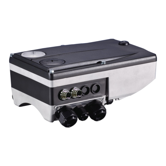
Communication manual 8400 motec EtherCAT® Product description Connections and interfaces Connections and interfaces E84DG029 [3-1] EtherCAT Communication Unit Pos. Description A1 / LED Position of LEDs for EtherCAT status display LED status displays ( 58) IN: EtherCAT input (M12 socket, 5-pole, D-coded) EtherCAT connection (... - Page 16 Communication manual 8400 motec EtherCAT® Product description Connections and interfaces On delivery, the EtherCAT connections and the LEDs for the EtherCAT status displays are already mounted and wired: – EtherCAT input to plug connector X31 – EtherCAT output to plug connector X32 –...
-
Page 17: Technical Data
Communication manual 8400 motec EtherCAT® Technical data General data and operating conditions Technical data "Inverter Drives 8400 motec" hardware manual Here you will find the ambient conditions and information on the electromagnetic compatibility (EMC) that also apply to the Communication Unit. -
Page 18: Protocol Data
Communication manual 8400 motec EtherCAT® Technical data Protocol data Protocol data Area Values Process data words 1 ... 10 process data words to master (max. 20 bytes, 16 bits / word) 1 ... 8 process data words from master (max. 16 bytes, 16 bits / word) Parameter data (mailbox size for CoE Max. -
Page 19: Installation
Communication manual 8400 motec EtherCAT® Installation Installation Stop! Electrostatic discharge Electronic components within the Communication Unit can be damaged or destroyed by electrostatic discharge. Possible consequences: • The Communication Unit is defective. • Fieldbus communication is troubled or not possible. •... -
Page 20: Mechanical Installation
Communication manual 8400 motec EtherCAT® Installation Mechanical installation Mechanical installation Mounting instructions for "Inverter Drives 8400 motec" Here you will find detailed information on the installation. 0.37 ... 3.0 kW 4.0 ... 7.5 kW E84DG023a E84DG023b [5-1] Mechanical installation of the 8400 motec components Legend for Fig. -
Page 21: Electrical Installation
Communication manual 8400 motec EtherCAT® Installation Electrical installation Electrical installation "Inverter Drives 8400 motec" hardware manual Here you will find detailed information about ... • the digital and analog inputs/outputs; • the relay output; • the integrated safety system (safety option); •... - Page 22 Communication manual 8400 motec EtherCAT® Installation Electrical installation Switch topology M = master S = switch SD = slave device E94AYCET007 [5-3] Switch topology The wiring can also be carried out in a star structure via an appropriate switch. For this, observe the additional runtimes.
-
Page 23: Ethercat Connection
Communication manual 8400 motec EtherCAT® Installation Electrical installation 5.2.2 EtherCAT connection EtherCAT input (IN) M12 socket, 5-pole, D-coded Wiring at terminal strip X31 Signal Description Tx + Data line (transmitted data, plus) Rx + Data line (received data, plus) Tx - Data line (transmitted data, minus) Rx -... -
Page 24: External Voltage Supply
Communication manual 8400 motec EtherCAT® Installation Electrical installation 5.2.3 External voltage supply The external voltage supply can be used to establish EtherCAT communication for commissioning purposes and to query the data of the digital and analog inputs. Moreover, the external voltage supply serves to keep up EtherCAT communication in the event of a main supply failure. -
Page 25: Commissioning
During commissioning, system-related data such as motor parameters, operating parameters, responses, and parameters for fieldbus communication are defined for the controller. For Lenze devices, this is done via the codes. The codes of the controller and communication are saved non-volatilely as a data set in the memory module. -
Page 26: Configuring The Host
The basic parameters of the Communication Unit are saved to the internal configuration memory and can be used by the master for the node identification. For the node search (fieldbus scan), the corresponding device descriptions of the Lenze device family are used. -
Page 27: Automatic Device Identification
Automatic device identification For troublefree integration of the EtherCAT slaves in a master configuration it is necessary to select the correct Lenze device from the EtherCAT configuration software. The configuration software unambiguously identifies an EtherCAT node by the product code (identical to CoE object I-1018.2), the manufacturer code (0x3B), and the main... -
Page 28: Configuring Process Data
Communication manual 8400 motec EtherCAT® Commissioning Configuring the host (master) 6.2.3 Configuring process data The process data configuration is determined during the initialisation phase of the master (PDO mapping). A maximum of 10 process data words (max. 20 bytes) can be sent to the master. ... -
Page 29: Determining The Cycle Time
Communication manual 8400 motec EtherCAT® Commissioning Configuring the host (master) The process data configuration is predefined in the device description file for each application and can be adjusted by the user if required. Configuring the port interconnection of the process data objects (PDO) (... -
Page 30: Address Allocation
Communication manual 8400 motec EtherCAT® Commissioning Address allocation Address allocation The EtherCAT nodes are normally addressed via a fixed 16-bit address defined by the EtherCAT master. During start-up, the master assigns this address to each node, depending on the physical order in the EtherCAT network. The address is not saved and is lost when the device is switched off. -
Page 31: Switch-On
Communication manual 8400 motec EtherCAT® Commissioning Initial switch-on Initial switch-on Establishing communication To establish communication, the controller must be supplied with mains voltage. The external voltage supply serves to keep up EtherCAT communication in the event of a main supply failure. External voltage supply (... -
Page 32: Data Transfer
Communication manual 8400 motec EtherCAT® Data transfer Data transfer EtherCAT transmits data in so-called "EtherCAT frames". The EtherCAT nodes only extract the data intended for them while the EtherCAT frame passes through the device. At the same time output data are inserted into the frame while it passes through the device. Read and write accesses are only executed on a small section of the entire EtherCAT frames –... -
Page 33: Ethercat Frame Structure
Communication manual 8400 motec EtherCAT® Data transfer EtherCAT frame structure EtherCAT frame structure EtherCAT frames have the following structure: Ethernet header Ethernet data 48 bits 48 bits 16 bits 11 bits 1 bit 4 bits 48 ... 1498 bytes 32 bits Destination Source EtherType... -
Page 34: Ethercat Datagrams
Communication manual 8400 motec EtherCAT® Data transfer EtherCAT datagrams EtherCAT datagrams EtherCAT datagrams have the following structure: EtherCAT Data Command header 10 bytes Max. 1486 bytes 2 bytes EtherCAT command header The EtherCAT command header contains the following information: Command to be executed ... -
Page 35: Ethercat State Machine
Communication manual 8400 motec EtherCAT® Data transfer EtherCAT state machine EtherCAT state machine Before communication is possible via EtherCAT, the fieldbus passes through the EtherCAT state machine during start-up. The following illustration depicts the possible state changes from the point of view of an EtherCAT slave: Init Pre-Operational Safe-Operational... - Page 36 Communication manual 8400 motec EtherCAT® Data transfer EtherCAT state machine AL Status Code Information on how to access the "AL Status Code" EtherCAT register (address 0x0134:0x0135) can be found in the documentation for the EtherCAT master. These error messages can be entered into the "AL Status Code" register: Code [hex] Description 0x0000...
-
Page 37: Process Data Transfer
Communication manual 8400 motec EtherCAT® Process data transfer Process data transfer Process data are transmitted by means of so-called EtherCAT datagrams via the ( 34) process data channel. The Inverter Drive 8400 motec is controlled by means of the process data. ... -
Page 38: Accessing Process Data / Pdo Mapping
The LP_Network_Out port block maps the MCI-PDOs to be sent. The port/function block interconnection of the process data objects (PDOs) is made via the Lenze »Engineer«. [8-1] Outer and inner data transfer between bus system, controller, and application ... -
Page 39: Configuring The Port Interconnection Of The Process Data Objects (Pdo)
Communication manual 8400 motec EtherCAT® Process data transfer Configuring the port interconnection of the process data objects (PDO) Configuring the port interconnection of the process data objects (PDO) Note! The following »Engineer« screenshots are only examples of the setting sequence and the resulting displays. - Page 40 Communication manual 8400 motec EtherCAT® Process data transfer Configuring the port interconnection of the process data objects (PDO) 3. Click the port to be configured and press the Change Variable... button. EDS84DMOTECAT EN 2.1 - 11/2012...
- Page 41 Communication manual 8400 motec EtherCAT® Process data transfer Configuring the port interconnection of the process data objects (PDO) 4. The button serves to assign signals to the process data words in the Assignment Signal --> Function Block dialog box. Select signals and then click the OK button. EDS84DMOTECAT EN 2.1 - 11/2012...
- Page 42 Communication manual 8400 motec EtherCAT® Process data transfer Configuring the port interconnection of the process data objects (PDO) For some process data words, you can also assign signals to the individual bits via buttons. Select the signals and then confirm the selection with OK. The current interconnection is only displayed if the following has been set for the control mode in code C00007 = 40: Network (MCI/CAN).
-
Page 43: Parameter Data Transfer
The SDO services provide for the write and read access to the object directory. The SDO channel provides for the access to Implemented CoE objects and Lenze ( 53) codes by means of the CoE protocol. In general, the parameter data transfer is not time-critical. -
Page 44: Reading And Writing Parameters
are set e.g. for one-time system settings or if materials are changed within a machine. are transmitted with a low priority. In the case of Lenze controllers, the parameters to be changed are contained in codes. Indexing of the Lenze codes The codes of the Inverter Drive 8400 motec are addressed by the index when accessed via the Communication Unit. -
Page 45: Reading Parameters
Note! In the case of jobs for the controller, please make sure that you convert the code into an index. Indexing of the Lenze codes ( 44) SDO Upload Request Detailed breakdown of the data for an "SDO Upload Request":... - Page 46 Communication manual 8400 motec EtherCAT® Parameter data transfer Reading and writing parameters SDO Upload Expedited Response An "SDO Upload Expedited Response" is carried out if the data length of the parameter data to be read amounts to a maximum of 4 bytes. Detailed breakdown of the data for an "SDO Upload Expedited Response": SDO frame area Data field...
- Page 47 Communication manual 8400 motec EtherCAT® Parameter data transfer Reading and writing parameters SDO Upload Normal Response An "SDO Upload Normal Response" is carried out if the data length of the parameter data to be read amounts to ≥ 4 bytes. Detailed breakdown of the data for an "SDO Upload Normal Response": SDO frame area Data field...
- Page 48 Communication manual 8400 motec EtherCAT® Parameter data transfer Reading and writing parameters Example The transmitted response structure during an Upload to index 0x5FD8 (standard value of C00039/1, Fixed_Setpoint_1 = 0x0FA0) includes the following data: SDO frame area Data field Data type / length Value / description Mailbox header Length...
-
Page 49: Writing Parameters (Sdo Download)
Note! In the case of jobs for the controller, please make sure that you convert the code into an index. Indexing of the Lenze codes ( 44) SDO Download Expedited Request An "SDO Download Expedited Request" is carried out if the data length of the parameter data to be written amounts to a maximum of 4 bytes. - Page 50 Communication manual 8400 motec EtherCAT® Parameter data transfer Reading and writing parameters SDO Download Normal Request An "SDO Download Normal Request" is carried out if the data length of the parameter data to be written amounts to ≥ 4 bytes. Detailed breakdown of the data for an "SDO Download Normal Request": SDO frame area Data field...
- Page 51 Communication manual 8400 motec EtherCAT® Parameter data transfer Reading and writing parameters SDO Download Response Detailed breakdown of the data for an "SDO Download Response": SDO frame area Data field Data type / length Value / description Mailbox header Length WORD 2 bytes 0x0A: Length of the mailbox service data...
- Page 52 Communication manual 8400 motec EtherCAT® Parameter data transfer Reading and writing parameters Example The transmitted request structure during a Download to index 0x1600 includes the following data: SDO frame area Data field Data type / length Value / description Mailbox header Length WORD 2 bytes...
-
Page 53: Implemented Coe Objects
Implemented CoE objects Implemented CoE objects Lenze devices can be parameterised with both Lenze codes and the manufacturer- independent "CoE objects". In order to comply fully with EtherCAT communication, you may only use the CoE objects for parameterisation. The CoE objects described in this manual are defined in the "EtherCAT Specification, Part 6 –... -
Page 54: Ethercat Objects Of The Communication Unit
Communication manual 8400 motec EtherCAT® Parameter data transfer EtherCAT objects of the Communication Unit EtherCAT objects of the Communication Unit The object directory displays the Parameters relevant for EtherCAT communication ( 67) as objects: Index Code Index name Subindex Subindex name Type Bits Access... -
Page 55: Sdo Abort Codes (Abort Codes)
Communication manual 8400 motec EtherCAT® Parameter data transfer SDO abort codes (Abort codes) SDO abort codes (Abort codes) If an SDO request is evaluated negatively, a corresponding error code is output. Index [hex] Description 0x00000000 No error 0x05030000 The status of the toggle bit has not changed 0x05040000 SDO time-out protocol 0x05040001... -
Page 56: Monitoring
Set a response delay (C13881) to delay execution of the response. • A Lenze setting of "No response" deactivates this monitoring. • Setting a response will activate the monitoring as long as a response time < 65356 ms is set. -
Page 57: Fault Of The Internal Communication
Communication manual 8400 motec EtherCAT® Monitoring Fault of the internal communication 3. Via standard device code C00002, execute the "11: Save all parameter sets" device command to activate the changed parameter settings and to save it to the memory module. 10.2 Fault of the internal communication ... -
Page 58: Diagnostics
Communication manual 8400 motec EtherCAT® Diagnostics LED status displays Diagnostics EtherCAT communication faults can be diagnosed via the LEDs of the Communication Unit. Moreover, the »Engineer« providesEtherCAT diagnostic information. 11.1 LED status displays E84DG056 Colour Status Description Link / green •... - Page 59 Communication manual 8400 motec EtherCAT® Diagnostics LED status displays Colour Status Description green The Communication Unit is not active on the fieldbus or is in the "Init" state. The Communication Unit is in the "Operational" state. blinking 200 ms 200 ms "Pre-operational"...
-
Page 60: Diagnostics With The "Engineer
Communication manual 8400 motec EtherCAT® Diagnostics Diagnostics with the »Engineer« 11.2 Diagnostics with the »Engineer« In the »Engineer« under the Diagnostics tab, various EtherCAT diagnostics information is displayed. EDS84DMOTECAT EN 2.1 - 11/2012... -
Page 61: Emergency Requests / Emergency Messages
Communication manual 8400 motec EtherCAT® Diagnostics Emergency requests / Emergency messages 11.3 Emergency requests / Emergency messages Emergency messages are sent to the EtherCAT master once when the error status changes, i.e ... if an error of the Inverter Drive 8400 motec or the Communication Unit occurs; ... -
Page 62: Error Messages
0x01bc6101 24833 Internal error 1: Error C01501/2 0x01bc641f 25631 Invalid parameter record 1: Error 0x01bc6420 25632 Error: Lenze setting loaded 1: Error 0x01bc6430 25648 Invalid module configuration 4: Warning locked 0x01bc8131 33073 "Operational" status quit 0: No response C13880 EDS84DMOTECAT EN 2.1 - 11/2012... -
Page 63: Possible Causes And Remedies
No response Error Fault Warning locked Cause Remedy Access to memory was not possible. Send the device and a description of the fault to Lenze. Memory: Read error [0x01bc5532] Response (Lenze setting printed in bold) Setting: C01501/2 adjustable response) No response... - Page 64 No response Error Fault Warning locked Cause Remedy Device is damaged. Send the device and a description of the fault to Lenze. Internal error [0x01bc6100] Response (Lenze setting printed in bold) Setting: C01501/2 adjustable response) No response Error...
- Page 65 Communication manual 8400 motec EtherCAT® Error messages Possible causes and remedies Operational status quit [0x01bc8131] Response (Lenze setting printed in bold) Setting: C13880/1 Adjustable response) No response Error Fault Warning locked Cause Remedy The EtherCAT data exchange was stopped in the •...
-
Page 66: Parameter Reference
C01501 | Resp. to communication error with MCI Configuration of monitoring functions for the Communication Unit Selection list 0 No response 1 Error 4 Warning locked Subcodes Lenze setting Info C01501/1 1: Error Resp. to MCI error 1 • Response to a communication error. C01501/2 1: Error Resp. -
Page 67: Parameters Relevant For Ethercat Communication
Communication manual 8400 motec EtherCAT® Parameter reference Parameters relevant for EtherCAT communication 13.2 Parameters relevant for EtherCAT communication This chapter lists the EtherCAT parameters of the Communication Unit in numerically ascending order. C13850 Parameter | Name: Data type: UNSIGNED_16 C13850 | All words from drive to master Index: 10725 = 29E5 Display of the process data words (subcodes 1 ... - Page 68 Communication manual 8400 motec EtherCAT® Parameter reference Parameters relevant for EtherCAT communication C13860 Parameter | Name: Data type: UNSIGNED_16 Index: 10715 = 29DB C13860 | All words from standard device Number of process data words to be received Display area (min.
- Page 69 The notes in code C13881 must be observed! Interruption of EtherCAT communication ( 56) Selection list 0 No response 1 Error 4 Warning locked Subcodes Lenze setting Info C13880/1 0: No response Read access Write access CINH PLC-STOP No transfer...
- Page 70 Communication manual 8400 motec EtherCAT® Parameter reference Parameters relevant for EtherCAT communication C13900 Parameter | Name: Data type: VISIBLE_STRING Index: 10675 = 29B3 C13900 | Firmware product type The code contains a string with a length of 8 bytes. The following identification code is displayed: "E84DFFET". Read access Write access CINH...
-
Page 71: Table Of Attributes
Name Parameter short text (display text) Text Index Index by which the parameter is addressed. 24575 - Lenze code number Only required for access via a bus The subindex for array variables corresponds to the system 5FFF - Lenze code number Lenze subcode number. - Page 72 Communication manual 8400 motec EtherCAT® Parameter reference Table of attributes Table of attributes Code Name Index Data Access Data type Factor CINH C13850 All words from drive to master 10725 29E5 UNSIGNED_16 C13851 All words from master to drive 10724 29E4 UNSIGNED_16 C13859...
-
Page 73: Index
C13851 | All words from master to drive Emergency messages C13859 | All words to standard device Emergency requests C13860 | All words from standard device Error: Lenze setting loaded (error message) C13861 | Bus state Error code C13864 | Active station address Error messages... - Page 74 Reading parameters (SDO Upload) Residual hazards Resp. to communication error with MCI (C01501) I/O data Response time when exiting "Operational" (C13881) Indexing of the Lenze codes Initial switch-on Restart by Watchdog Reset (error message) Installation Revision ID Installing device description files...
- Page 75 Communication manual 8400 motec EtherCAT® Index Upload Validity of the documentation Variants Vendor ID Voltage supply Writing parameters (SDO Download) EDS84DMOTECAT EN 2.1 - 11/2012...
- Page 76 © 11/2012 Lenze Drives GmbH Service Lenze Service GmbH P.O. Box 10 13 52 Breslauer Straße 3 D-31763 Hameln D-32699 Extertal Germany Germany +49 (0)51 54 / 82-0 00 80 00 / 24 4 68 77 (24 h helpline)
Need help?
Do you have a question about the L-force 8400 motec and is the answer not in the manual?
Questions and answers