Sign In
Upload
Manuals
Brands
LeCroy Manuals
Measuring Instruments
SDA
LeCroy SDA Manuals
Manuals and User Guides for LeCroy SDA. We have
1
LeCroy SDA manual available for free PDF download: Operator's Manual
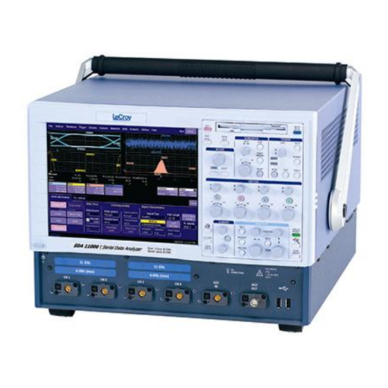
LeCroy SDA Operator's Manual (397 pages)
SERIAL DATA ANALYZER
Brand:
LeCroy
| Category:
Measuring Instruments
| Size: 7 MB
Table of Contents
Table of Contents
3
Introduction
18
How to Use Online Help
18
Type Styles
18
Instrument Help
18
Windows Help
19
Returning a Product for Service or Repair
19
Technical Support
19
Staying Up-To-Date
20
Warranty
20
Windows License Agreement
20
End-User License Agreement for Lecroy X-Stream Software
21
Virus Protection
27
SDA Specifications
28
Vertical System
28
Horizontal System
29
Jitter Noise Floor
29
Acquisition System
29
Memory
30
Sda 18000/13000/11000/9000
30
Acquisition Modes
30
Acquisition Processing
30
Triggering System
30
Automatic Setup
31
Probes
31
Basic Triggers
31
SMART Triggers
31
SMART Triggers with Exclusion Technology
31
Serial Trigger
32
Clock Recovery
32
Jitter Analysis
32
Math Tools - Standard
33
Automated Measure Tools - Standard
33
Pass/Fail Testing
34
Advanced Math Package (XMATH) - Standard
34
Jitter and Timing Analysis Package (JTA2) - Standard
34
ASDA-J - Standard
35
8B/10B Protocol Decoding - Standard
35
Advanced Customization Package (XDEV) - Optional
35
Color Waveform Display
35
Analog Persistence Display
36
Zoom Expansion Traces
36
Cpu
36
Internal Waveform Memory
36
Setup Storage
36
Interface
36
Auxiliary Output
36
Auxiliary Input
36
General
37
Environmental Characteristics
37
Certifications
37
CE Declaration of Conformity
37
Physical Dimensions
38
Warranty and Service
39
Optical Reference Receiver (with OE425/OE455)
39
Software Clock Recovery System
39
Communications Mask Testing
40
Jitter Testing
40
Bit Error Rate (Optional)
41
Safety
42
Safety Requirements
42
Safety Symbols
42
Operating Environment
43
Cooling
44
AC Power Source
44
Power Consumption
45
Power and Ground Connections
45
Standby (Power) Switch and Scope Operational States
46
Fuse Replacement
46
Calibration
47
Cleaning
47
Abnormal Conditions
47
Basic Controls
48
Alternate Access Methods
48
Mouse and Keyboard Operation
48
Toolbar Buttons
48
Trace Descriptors
49
Trace Annotation
50
Annotating a Waveform
51
Turning on a Channel Trace Label
52
Installation
53
Software
53
Checking the Scope Status
53
Default Settings
53
DDA, SDA, and Waverunner Dsos
53
Adding a New Option
53
Restoring Software
54
Restarting the Application
54
Restarting the Operating System
55
Removable Hard Drive
55
Connecting to a Signal
56
Probus Interface
56
Prolink Interface
56
Connecting the Adapters
58
AP-1M Hi-Z Adapter
59
Auxiliary Output Signals
60
Auxiliary Output Setup
60
Sampling Modes
61
Sampling Mode Selection
61
Single-Shot Sampling Mode
61
Basic Capture Technique
61
Sequence Sampling Mode Working with Segments
62
Sequence Mode Setup
63
Sequence Display Modes
64
Displaying Individual Segments
65
Viewing Time Stamps
66
RIS SAMPLING Mode - for Higher Sample Rates
66
Roll Mode
67
Vertical Settings and Channel Controls
67
Adjusting Sensitivity and Position
67
Adjusting Sensitivity
67
Adjusting the Waveform's Position
68
Coupling
68
Overload Protection
68
Coupling Setup
68
Probe Attenuation
68
Setting Probe Attenuation
68
Bandwidth Limit
69
Linear and (Sinx)/X Interpolation
69
Interpolation Setup
69
Inverting Waveforms
69
Quickzoom
69
Turning on a Zoom
69
Finding Scale
70
Using Find Scale
70
Variable Gain
70
Enabling Variable Gain
70
Channel Deskew
70
Channel Deskew Setup
70
Group Delay Compensation
71
Timebase and Acquisition System
72
Timebase Setup and Control
72
Autosetup
72
SDA DBI Controls
72
SDA18000 DBI Controls
72
SDA 13000/11000/9000 DBI Controls
73
Smart Memory
73
SMART Memory Setup
74
External Timebase Vs. External Clock
74
Triggering
74
Trigger Setup Considerations
74
Trigger Modes
74
Trigger Types
75
Determining Trigger Level, Slope, Source, and Coupling
76
Trigger Source
77
Level
77
Holdoff by Time or Events
77
Hold off by Time
78
Hold off by Events
79
Simple Triggers
79
Edge Trigger on Simple Signals
79
Control Edge Triggering
80
Edge Trigger Setup
80
SMART Triggers
83
Width Trigger
83
Glitch Trigger
84
Interval Trigger
85
Qualified Trigger
89
State Trigger
91
Dropout Trigger
92
Logic Trigger
94
Serial Trigger
95
Aux Input Trigger
95
Aux Input Setup
95
Display Formats
96
Display Setup
96
Sequence Mode Display
97
Persistence Setup
97
Saturation Level
97
3-Dimensional Persistence
98
Show Last Trace
99
Persistence Time
100
Locking of Traces
100
Persistence Setup
100
Screen Saver
101
Moving Traces from Grid to Grid
101
Zooming Waveforms
102
Zooming a Single Channel
103
Zooming by Touch-And-Drag
103
Zooming Multiple Waveforms Quickly
104
Multi-Zoom
104
XY Display
105
XY Display Setup
106
Save and Recall
106
Saving and Recalling Scope Settings
106
Saving Scope Settings
106
Recalling Scope Settings
107
Recalling Default Settings
107
Saving Screen Images
107
Saving and Recalling Waveforms
108
Saving Waveforms
108
Recalling Waveforms
110
Disk Utilities
110
Deleting a Single File
110
Deleting All Files in a Folder
111
Creating a Folder
111
Printing and File Management
111
Print, Plot, or Copy
111
Printing
111
Printer Setup
111
Printing
112
Adding Printers and Drivers
112
Changing the Default Printer
112
Managing Files
112
Hard Disk Partitions
112
100Base-T Ethernet Connection
113
Connecting to a Network
113
Communicating over the Network
113
Windows Setups
113
System Restore
114
Track Views
114
Creating and Viewing a Trend
114
Creating a Track View
115
Histograms
116
Creating and Viewing a Histogram
116
Single Parameter Histogram Setup
116
Viewing Thumbnail Histograms
118
Persistence Histogram
118
Persistence Trace Range
118
Persistence Sigma
118
Histogram Parameters
119
Histogram Theory of Operation
132
DSO Process
133
Parameter Buffer
133
Capture of Parameter Events
134
Histogram Parameters (XMAP and JTA2 Options)
134
Histogram Peaks
135
Binning and Measurement Accuracy
135
Waveform Measurements
136
Measuring with Cursors
136
Cursor Measurement Icons
136
Cursors Setup
137
Quick Display
137
Full Setup
137
Overview of Parameters
137
Turning on Parameters
137
Quick Access to Parameter Setup Dialogs
138
Status Symbols
139
Using X-Stream Browser to Obtain Status Information
139
Statistics
141
Applying a Measure Mode
141
Measure Modes
141
Standard Vertical Parameters
141
My Measure
142
Parameter Math (Xmath or XMAP Option Required)
142
Logarithmic Parameters
142
Excluded Parameters
142
Parameter Script Parameter Math
143
Param Script Vs. P Script
143
Parameter Math Setup
144
Parameter Script Math Setup
144
Measure Gate
145
Measure Gate Setup
146
Help Markers
147
Help Marker Setup
149
Turning off Help Markers
149
Customizing a Parameter
149
From the Measure Dialog
149
From a Vertical Setup Dialog
150
From a Math Setup Dialog
150
Parameter Calculations
150
Parameters and How They Work
150
Determining Time Parameters
152
Determining Differential Time Measurements
154
Level and Slope
154
List of Parameters
155
Qualified Parameters
177
Range Limited Parameters
177
Waveform Gated Parameters
178
Waveform Qualifier Setup
178
Waveform Math
178
Introduction to Math Traces and Functions
178
Math Made Easy
179
Setting up a Math Function
179
Resampling to Deskew
180
Resampling
180
Rescaling and Assigning Units
180
Rescaling Setup
182
Averaging Waveforms
182
Summed Vs. Continuous Averaging
182
Continuous Averaging Setup
184
Summed Averaging Setup
184
Enhanced Resolution
184
How the Instrument Enhances Resolution
184
Enhanced Resolution (ERES) Setup
187
Waveform Copy
187
Waveform Sparser
187
Waveform Sparser Setup
188
Interpolation
188
Interpolation Setup
188
Fast Wave Port
188
Fast Wave Port Setup - Initial
189
Setup - Case 1
190
Setup - Case 2
190
Setup - Case 3
190
Operational Notes
191
Data Length Limitations
191
Performance
191
Choice of Programming Language
191
Example Application
191
Header Description
194
Data Length Limitations
195
Performance
195
Choice of Programming Language
195
Fft
195
Why Use FFT
195
Improving Dynamic Range
198
Record Length
198
FFT Algorithms
199
Glossary
200
FFT Setup
203
Analysis
204
Pass/Fail Testing
204
Comparing Parameters
204
Mask Tests
205
Actions
205
Setting up Pass/Fail Testing
206
Initial Setup
206
Comparing a Single Parameter
206
Comparing Dual Parameters
208
Mask Testing
209
Utilities
210
Status
210
Status Dialog Access
210
Remote Communication
210
Remote Communication Setup
210
Configuring the Remote Control Assistant Event Log
211
Hardcopy
211
Printing
211
Clipboard
211
File
211
E-Mail
212
Aux Output
212
Date & Time
212
Setting the Time and Date Manually
212
Setting the Time and Date from the Internet
213
Setting the Time and Date from Windows
213
Options
214
Preferences
214
Audible Feedback
214
Auto-Calibration
214
Offset Control
214
Delay Control
215
Trigger Counter
215
Performance Optimization
215
E-Mail
216
Acquisition Status
216
Service
217
Show Windows Desktop
217
Touch-Screen Calibration
217
Customization
218
Customizing Your Instrument
218
Introduction
218
Solutions
219
Examples
219
What Is Excel
224
What Is Mathcad
224
What Is MATLAB
224
What Is VBS
224
What Can You Do with a Customized Instrument
226
Number of Samples
227
Calling Excel from Your Instrument
227
How to Select a Math Function Call
227
How to Select a Parameter Function Call
227
The Excel Control Dialog
228
Entering a File Name
228
Organizing Excel Spreadsheets
229
Setting the Vertical Scale
230
Trace Descriptors
230
Multiple Inputs and Outputs
230
Simple Excel Example 1
231
Simple Excel Example 2
234
Excel Example 1: Exponential Decay Time Constant Excel Parameter
238
Excel Example 2: Gated Parameter Using Excel
239
How Does this Work
241
Excel Example 3: Correlation Excel Waveform Function
242
Excel Example 4: Multiple Traces on One Grid
244
Excel Example 5: Using a Surface Plot
247
Writing Vbscripts
248
Types of Scripts in VBS
248
Loading and Saving Vbscripts
248
The Default Parameter Function Script: Explanatory Notes
251
Scripting with Vbscript
252
Variable Types
252
Variable Names
253
Arithmetic Operators
254
VBS Controls
255
Summary of if
257
Select Case
258
Summary of Select Case
258
While
259
For
259
VBS Keywords and Functions
260
Other VBS Words
261
Functions
262
Hints and Tips for Vbscripting
263
Errors
264
Error Handling
266
Speed of Execution
266
Scripting Ideas
267
Debugging Scripts
267
Horizontal Control Variables
268
Vertical Control Variables
268
List of Variables Available to Scripts
268
Communicating with Excel from a Vbscript
269
Calling MATLAB from the Instrument
270
How to Select a Waveform Function Call
271
The MATLAB Waveform Control Panel
272
MATLAB Waveform Function Editor - Example
272
MATLAB Example Waveform Plot
274
How to Select a MATLAB Parameter Call
274
The MATLAB Parameter Control Panel
275
The MATLAB Parameter Editor
275
MATLAB Example Parameter Panel
276
More Examples of MATLAB Waveform Functions
277
Creating Your Own MATLAB Function
280
Customdso
281
What Is Customdso
281
Invoking Customdso
281
Customdso Basic Mode
282
Editing a Customdso Setup File
282
Creating a Customdso Setup File
283
Customdso Plugin Mode
284
Creating a Customdso Plugin
284
Properties of the Control and Its Objects
285
Removing a Plugin
288
Plugin Example 1: Exchanging Two Traces on the Grids
289
Second Example Plugin: Log-Log FFT Plot
291
Control Variables in Customdso
293
Labnotebook
293
Introduction to Labnotebook
293
Preferences
293
Miscellaneous Settings
293
Hardcopy Setup
294
E-Mail Setup
294
Creating a Notebook Entry
294
Recalling Notebook Entries
298
Creating a Report
299
Previewing a Report
299
Locating a Notebook Entry
299
Creating the Report
299
Formatting the Report
300
Managing Notebook Entry Data
301
Adding Annotations
301
Deleting Notebook Entries
301
Saving Notebook Entries to a Folder
301
Managing the Database
301
Starting a New Database
302
Processing Web Option
302
Using the Web Editor
303
Adding Parameters
305
Adding Previews
305
Exiting the Web Editor
305
Viewing the Output
306
Serial Data Analyzer
306
Serial Data Analyzer Standard and Optional Capabilities
306
SDA Capabilities
306
SDM Capabilities
307
ASDA-J Capabilities
307
Jitter Wizard
309
SDA Basic Setup
312
PLL Setup
315
Summary
317
Mask Test
317
Eye Setup
318
Mask Margin
319
Testing
320
Bit Error Rate - ASDA-J Option Only
320
Serial Trigger
321
Serial Trigger Setup
322
PLL Locking
323
Setting the Data Pattern
323
Storing and Recalling Serial Data Patterns into the Trigger
325
Using the Serial Pattern Trigger
325
Jitter Setup
325
SDA DBI Controls
329
SDA 13000/11000/9000 DBI Controls
329
Vertical Noise Calibration
330
Running the Script
330
Using Noise Compensation
331
Jitter Measurements
332
Pj Breakdown
333
Alternate Jitter Breakdown Methods (Option ASDA-J Only)
333
Effective Jitter
333
MJSQ Jitter
335
Bathtub Curve
336
Jitter Filter
337
TIE Histogram
337
DDJ (Synchronous N-Cycle Plot)
338
Ddj (ISI Plot) - ASDA-J Option Only
339
Edge-To-Edge Basic Setup
341
Edge-Edge Jitter Measurements
342
Edge-Edge Jitter Measurement Controls
345
Adjust Rj
345
Async N Cycle Plot
345
Edge-Edge Spacing Controls
345
SDA Function Reference
346
Altncycle
347
Altncycle Control Summary
348
Htie to BER
350
Jitter Filter Function
352
Slice2Persist
353
Multi-Eye Measurements
355
Overview of Multi-Eye Measurement Tools
355
Setup and Installation
356
Multi-Eye Setup and Installation
356
Example Setups
357
Front Side Bus (FSB)
359
Introduction to FSB
359
FSB Theory of Operation
360
Transition/Non-Transition Eye Diagram
363
Gated (Qualified) Eye Diagram
364
SDA Theory
365
Clock Recovery
365
Eye Pattern
368
Eye Violation Locator (ASDA Option)
369
Eye Pattern Measurements
370
Eye Amplitude
370
Eye Height
371
Eye Width
371
Extinction Ratio
371
Eye Crossing
371
Average Power
371
Q Factor or BER
372
Eyeber
372
Jitter Measurement
373
Bit Error Rate and Jitter
375
Total Jitter
375
Extrapolating the PDF
377
Separating Rj and Dj - Two Methods
379
Effective Random and Deterministic Jitter
379
Direct Measurement of Deterministic Jitter
380
Comparing Models
382
Bit Error Rate
383
Bit Error Map
383
Vertical Noise Compensation
385
Introduction
385
Signal Slew Rate and How Vertical Noise Converts to Jitter
385
The Relative Impact of Noise on Jitter (Quadratic Addition of Noise)
386
How the Measurement System Noise Is Subtracted from the Jitter Measurement
386
Q-Scale Theory
386
Introduction
386
Interpretation of TIE Histogram - the Distribution of Edge Transition Times Vs. Ideal (Expected) Transition Times
387
Relationship between Histograms and PDF
387
Integrating the Pdfs
388
Extrapolation of the Distribution Tails (Extremes)
389
The Error Function Erf(X), Inverse Error Function Erf (X) and Related Functions
389
The Relationship between the Inverse Error Function and Total Jitter
390
Application of Error Function to Measured Jitter CDF (on Q-Scale)
391
Automatic Renormalization of the Q-Scale
393
Obtaining Deterministic and Random (Gaussian) Components from the Normalized Q-Scale Diagram
396
Advertisement
Advertisement
Related Products
LeCroy SDA 7 Zi series
LeCroy Wave Surfer WS-GPIB
LeCroy SATASuite
LeCroy 3377
LeCroy Advisor
LeCroy AP034
LeCroy DXC100A
LeCroy HFP1000
LeCroy LogicStudio
LeCroy LSA1000
LeCroy Categories
Test Equipment
Measuring Instruments
Amplifier
Inverter
Cables and connectors
More LeCroy Manuals
Login
Sign In
OR
Sign in with Facebook
Sign in with Google
Upload manual
Upload from disk
Upload from URL