Sign In
Upload
Manuals
Brands
JUKI Manuals
Sewing Machine
LU-1510N-7
JUKI LU-1510N-7 Manuals
Manuals and User Guides for JUKI LU-1510N-7. We have
3
JUKI LU-1510N-7 manuals available for free PDF download: Instruction Manual, Engineer's Manual
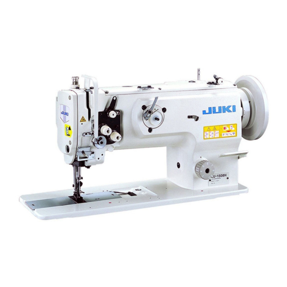
JUKI LU-1510N-7 Instruction Manual (104 pages)
Brand:
JUKI
| Category:
Sewing Machine
| Size: 2 MB
Table of Contents
Inhalt
40
Table of Contents
40
Vor dem Betrieb zu Beachten
43
Technische Daten
46
Installation
49
Einstellen der Riemenspannung
52
Überprüfen der Stoppposition
53
Anbringen der Riemenabdeckung
55
Luftantriebseinheit für Nähmaschinen mit Automatischer Rückwärtsnähvorrichtung und Auto-Lifter
57
Installieren des Garnständers
60
Schmierung
61
Anbringen der Nadel
67
Einsetzen/Entfernen der Spule
69
Einfädeln des Greifers
70
Installieren der Spulerfadenführung
71
Bewickeln einer Spule
71
Einfädeln des Maschinenkopfes
73
Einstellen der Stichlänge
76
Fadenspannung
77
Fadenanzugsfeder
79
Handlifter
80
Einstellen des Nähfussdrucks
81
Nadel-Greifer-Beziehung
82
Einstellen des Greifernadelschutzes
85
Einstellen des Spulenkapsel-Freigabehebels
87
Position des Gegenmessers und Einstellung des Messerdrucks
88
Einstellen des Hubbetrags von Nähfuss und Lauffuss
91
Nähgeschwindigkeitstabelle
91
Rückstellen der Sicherheitskupplung
93
Einstellen der Automatischen Nähfusslüftung
94
27. Nähstörungen und Abhilfemassnahmen
98
Sommaire
44
Avant L'utilisation
44
Caracteristiques
47
Reglage de la Tension de Courroie
52
Verification de la Position D'arret
53
Pose du Couvre-Courroie
55
Installation de L'unite Pneumatique de la Machine Avec Dispositif D'entrainement Arriere Automatique/Releveur Automatique
57
Pose du Porte-Bobines
60
Lubrification
61
Pose de L'aiguille
67
Pose/Retrait de la Canette
69
Enfilage du Crochet
70
Pose du Guide-Fil du Bobineur
71
Bobinage D'une Canette
71
Enfilage de la Tete de la Machine
73
Reglage de la Longueur des Points
76
Tension des Fils
77
Ressort de Relevage du Fil
79
Releveur Manuel
80
Reglage de la Pression du Pied Presseur
81
Relation entre L'aiguille Et Le Crochet
82
Reglage du Pare-Aiguille de Crochet
85
Reglage du Levier D'ouverture de la Boite a Canette
87
Position du Couteau Fixe Et Reglage de la Pression du Couteau
88
Reglage de la Hauteur de Relevage du Pied Presseur Et du Pied Trotteur
91
Tableau des Vitesses de Couturel
91
Rearmement de L'embrayage de Securite
93
Reglage du Releve-Presseur Automatique
94
27. Problemes de Couture Et Remedes
99
Indice
44
Antes de la Operacion
44
Misure DI Sicurezza da Adottare Prima Della Messa in Funzione
45
Especificaciones
47
Caratteristiche Tecniche
48
Instalacion
49
Installazione
49
Modo de Ajustar la Tensión de la Correa
52
Regolazione Della Tensione Della Cinghia
52
Modo de Comprobar la Posición de Parada
53
Controllo Della Posizione D' Arresto
53
Modo de Colocar la Cubierta de la Correa
55
Fissaggio del Copricinghia
55
Unidad Impulsora Neumática de la Maquina de Coser Equipada con
57
Un Dispositivo de Transporte Inverso Automatico/Elevador Automatico
57
Unità DI Comando Ad Aria Della Macchina Per Cucire Dotata DI Dispositivo DI Affrancatura Alzapiedino Automatico
57
Modo de Instalar el Pedestal de Hilos
60
Installazione del Portafilo
60
Lubricacion
61
Lubrificazione
61
Modo de Colocar la Aguja
67
Posizionamento Ago
67
Modo de Meter y de Sacar la Bobina
69
Inserimento Rimozione Della Bobina
69
Modo de Enhebrar el Gancho
70
Infilatura del Filo Nael Crochet
70
Modo de Instalar la Aguja de Hilo de la Bobinadora de Bobina
71
Modo de Bobinar una Bobina
71
Installazione del Guidafilo Dell'avvolgibobina
71
Avvolgimento Della Bobina
71
Modo de Enhebrar el Cabezal de la Maquina
73
Infilatura del Filo Nella Testa Della Macchina
73
Modo de Ajustar la Longitud de Puntada
76
Regolazione Della Lunghezza del Punto
76
Tension del Hilo
77
Tensione del Filo
77
Muelle del Tirahilo
79
Molla Tirafilo
79
Elevador de Mano
80
Alzapiedino Manuale
80
Modo de Ajustar la Presion del Prensatelas
81
Regolazione Della Pressione del Piedino Premistoffa
81
Relacion de Aguja a Gancho
82
Relazione Fase Ago-Crochet
82
Modo de Ajustar el Protector de Aguja de Gancho
85
Regolazione Della Protezione Ago del Crochet
85
Modo de Ajustar la Palanca de Abrir la Cápsula de Bobina
87
Regolazione Della Leva DI Apertura Della Capsula Della Bobina
87
Posicion de la Contracuchilla y Ajuste de Presion de la Cuchilla
88
Posizione del Contro-Lama E Regolazione Della Pressione del Coltello
88
Modo de Ajustar la Cantidad de Elevación del Prensatelas y del Pie Móvil
91
Tabla de Velocidades de Cosido
91
Regolazione Della Quantità DI Sollevamento del Piedino Premistoffa E del Piedino Mobile 49 24. Tabella Velocità DI Cucitura
91
Modo de Reposicionar el Embrague de Seguridad
93
Ripristino Della Frizione DI Sicurezza
93
Modo de Ajustar el Elevador Automatico del Prensatelas
94
Regolazione Dell'alzapiedino Automatico
94
Problemas en el Cosido y Medidas Correctivas
100
27. Inconvenienti in Cucitura E Rimedi
101
Advertisement
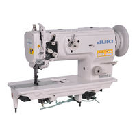
JUKI LU-1510N-7 Engineer's Manual (80 pages)
Juki Lockstitch Machines Engineer's manual
Brand:
JUKI
| Category:
Sewing Machine
| Size: 0 MB
Table of Contents
Table of Contents
3
Specifications
3
Lubrication Route Diagram
4
Drawing of the Table
4
Specifications
5
Standard Adjustment
10
Needle Entry Position
10
Longitudinal Position of the Feed Dog
10
Lateral Position of the Feed Dog
12
Height of the Feed Dog
12
Height of the Hook
14
Adjusting the Inner Hook Guide
14
Needle-To-Hook Timing
16
Lift of the Presser Foot
18
Hand Lifter
18
Knee Lifter (Without Thread Trimmer Only)
18
Automatic Presser Foot Lifter (Machine with Thread Trimmer Only)
20
Timing between the Upper Shaft and the Lower Shaft
20
Feed Cam Timing
22
Horizontal Feed Cam Timing
22
Top Feed Cam Timing
24
Feed Motion
26
Amount of Alternate Vertical Movement (Position of the Vertical Adjusting Arm)
26
Alternate Momentum
28
Needle Sway (Adjusting the Bottom Feed Amount)
28
Stitch Length of Normal/Reverse Feed
30
Balancer (Machine Without Thread Trimmer Only)
30
Vertical Position of the Needle Bar Rocking Frame
32
Dimension of the Needle Stop Adjusting Slide Shaft (Asm.)
34
Position of the Change Lever
34
Position of the Reverse Feed Control Lever
36
Safety Clutch
36
Reverse Feed Cylinder
38
Lubrication
38
In Case of Manual Lubrication
38
In Case of Automatic Lubrication
40
Thread Trimmer Device
42
Position of the Counter Knife and the Clamp Spring
42
Position of the Counter Knife Base
44
Vertical Position of the Moving Knife
44
Adjusting the Knife Pressure
46
Thread Trimmer Cam
46
Thread Trimmer Cam Timing
48
Connecting the Rocking Arm and the Thread Trimmer Roller Arm
48
Connecting the Left and Right Rocking Arms (2-Needle Machine Only)
50
Thread Trimmer Solenoid
50
Alternate Vertical Dial
52
Installing Position of the Detection Switch of the Amount of Alternate Vertical Movement
52
Installation of the Optional Parts
54
DL Device (for the Machine with Thread Trimmer Only)
54
Thread Trimmer Ver.up Set (Part No. for 1-Needle : 21389259, Part No. for 2-Needle : 21389267)
55
Bobbin Thread Remaining Amount Detecting Device (AE-10A Kit Part No. : GAE10000AA0)
55
Automatic Reverse Feed Device
56
Removing the Window Plate (Removing Parts List)
56
Removing the Reverse Feed Control Lever (Removing Parts List)
56
Installing the Reverse Feed Link Hinge Screw (List 1)
56
Installing the Reverse Feed Control Lever (List 2)
57
Installing the Automatic Reverse Feed Device (List 3)
58
Installing the Touch-Back Switch (List 4)
59
Installing the Pneumatic Components (List 5)
59
Automatic Presser Foot Lifter
60
Installing the Automatic Presser Foot Lifter (List A)
60
Installing the Pneumatic Device Components
61
Parts List
62
Portion to Which Locktite Is Applied
63
Selective Parts and Consumable Parts
64
Engraved Marker Dots on the Handwheel (for the Machine with Thread Trimmer Only)
65
Lubrication Route Diagram
65
Machine Head Wiring (for the Machine with Thread Trimmer Only)
66
Connectors Coming from Machine Head
66
Connectors Coming from Pneumatic Device
66
Connectors Coming from the Relay Cable (Connecting Side to the Control Box)
67
Table of Troubles and Corrective Measures
69
With Reagard to Sewing
69
With Regard to Thread Trimming
73
Drawing of the Table
79
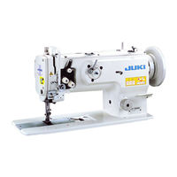
JUKI LU-1510N-7 Engineer's Manual (81 pages)
Brand:
JUKI
| Category:
Sewing Machine
| Size: 1 MB
Table of Contents
Table of Contents
3
Specifications
5
Standard Adjustment
12
Needle Entry Position
12
Longitudinal Position of the Feed Dog
12
Lateral Position of the Feed Dog
14
Height of the Feed Dog
14
Height of the Hook
16
Adjusting the Inner Hook Guide
16
Needle-To-Hook Timing
18
Lift of the Presser Foot
20
Hand Lifter
20
Knee Lifter (Without Thread Trimmer Only)
20
Automatic Presser Foot Lifter (Machine with Thread Trimmer Only)
22
Timing between the Upper Shaft and the Lower Shaft
22
Feed Cam Timing
24
Horizontal Feed Cam Timing
24
Top Feed Cam Timing
26
Feed Motion
28
Amount of Alternate Vertical Movement (Position of the Vertical Adjusting Arm)
28
Alternate Momentum
30
Needle Sway (Adjusting the Bottom Feed Amount)
30
Stitch Length of Forward/Reverse Feed
32
Balancer (Machine Without Thread Trimmer Only)
32
Vertical Position of the Needle Bar Rocking Frame
34
Dimension of the Needle Stop Adjusting Slide Shaft (Asm.)
36
Position of the Change Lever
36
Position of the Reverse Feed Control Lever
38
Safety Clutch
38
Reverse Feed Cylinder
40
Lubrication
40
In Case of Manual Lubrication
40
In Case of Automatic Lubrication
42
Thread Trimmer Device
44
Position of the Counter Knife and the Clamp Spring
44
Position of the Counter Knife Base
46
Vertical Position of the Moving Knife
46
Adjusting the Knife Pressure
48
Thread Trimmer Cam
48
Thread Trimmer Cam Timing
50
Connecting the Rocking Arm and the Thread Trimmer Roller Arm
50
Connecting the Left and Right Rocking Arms (2-Needle Machine Only)
52
Thread Trimmer Solenoid
52
Alternate Vertical Dial
54
Installing Position of the Detection Switch of the Amount of Alternate Vertical Movement
54
Installation of the Optional Parts
56
DL Device (for the Machine with Thread Trimmer Only)
56
Thread Trimmer Ver.up Set (Part No. for 1-Needle : 21389259, Part No. for 2-Needle : 21389267)
57
Bobbin Thread Remaining Amount Detecting Device (AE-10A Kit Part No. : GAE10000AA0)
57
Automatic Reverse Feed Device
58
Removing the Window Plate (Removing Parts List)
58
Removing the Reverse Feed Control Lever (Removing Parts List)
58
Installing the Reverse Feed Link Hinge Screw (List 1)
58
Installing the Reverse Feed Control Lever (List 2)
59
Installing the Automatic Reverse Feed Device (List 3)
60
Installing the Touch-Back Switch (List 4)
61
Installing the Pneumatic Components (List 5)
61
Automatic Presser Foot Lifter
62
Installing the Automatic Presser Foot Lifter (List A)
62
Installing the Pneumatic Device Components
63
Parts List
64
Portion to Which Locktite Is Applied
65
Selective Parts and Consumable Parts
66
Engraved Marker Dots on the Handwheel (for the Machine with Thread Trimmer Only)
67
Lubrication Route Diagram
67
Machine Head Wiring (for the Machine with Thread Trimmer Only)
68
Connectors Coming from Machine Head
68
Connectors Coming from Pneumatic Device
69
Connectors Coming from the Relay Cable (Connecting Side to the Control Box)
70
Table of Troubles and Corrective Measures
71
With Regard to Sewing
71
With Regard to Thread Trimming
75
Drawing of the Table
79
Advertisement
Advertisement
Related Products
JUKI LU-1511N-7
JUKI LU-1510N
JUKI LU-1510
JUKI LU-1510-7
JUKI LU-1510NA-7
JUKI LU-1520N-7
JUKI LU-1509N
JUKI LU-1508NH
JUKI LU-1560N
JUKI LU-1560N-7
JUKI Categories
Sewing Machine
Industrial Equipment
Sewing Machine Accessories
Accessories
Measuring Instruments
More JUKI Manuals
Login
Sign In
OR
Sign in with Facebook
Sign in with Google
Upload manual
Upload from disk
Upload from URL