Sign In
Upload
Manuals
Brands
JUKI Manuals
Sewing Machine
LU-1510N
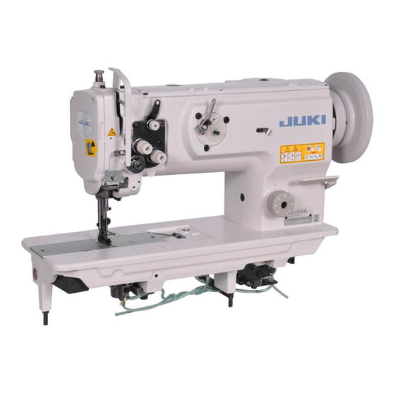
JUKI LU-1510N Manuals
Manuals and User Guides for JUKI LU-1510N. We have
2
JUKI LU-1510N manuals available for free PDF download: Engineer's Manual
JUKI LU-1510N Engineer's Manual (80 pages)
Juki Lockstitch Machines Engineer's manual
Brand:
JUKI
| Category:
Sewing Machine
| Size: 0 MB
Table of Contents
Table of Contents
3
Specifications
3
Lubrication Route Diagram
4
Drawing of the Table
4
Specifications
5
Standard Adjustment
10
Needle Entry Position
10
Longitudinal Position of the Feed Dog
10
Lateral Position of the Feed Dog
12
Height of the Feed Dog
12
Height of the Hook
14
Adjusting the Inner Hook Guide
14
Needle-To-Hook Timing
16
Lift of the Presser Foot
18
Hand Lifter
18
Knee Lifter (Without Thread Trimmer Only)
18
Automatic Presser Foot Lifter (Machine with Thread Trimmer Only)
20
Timing between the Upper Shaft and the Lower Shaft
20
Feed Cam Timing
22
Horizontal Feed Cam Timing
22
Top Feed Cam Timing
24
Feed Motion
26
Amount of Alternate Vertical Movement (Position of the Vertical Adjusting Arm)
26
Alternate Momentum
28
Needle Sway (Adjusting the Bottom Feed Amount)
28
Stitch Length of Normal/Reverse Feed
30
Balancer (Machine Without Thread Trimmer Only)
30
Vertical Position of the Needle Bar Rocking Frame
32
Dimension of the Needle Stop Adjusting Slide Shaft (Asm.)
34
Position of the Change Lever
34
Position of the Reverse Feed Control Lever
36
Safety Clutch
36
Reverse Feed Cylinder
38
Lubrication
38
In Case of Manual Lubrication
38
In Case of Automatic Lubrication
40
Thread Trimmer Device
42
Position of the Counter Knife and the Clamp Spring
42
Position of the Counter Knife Base
44
Vertical Position of the Moving Knife
44
Adjusting the Knife Pressure
46
Thread Trimmer Cam
46
Thread Trimmer Cam Timing
48
Connecting the Rocking Arm and the Thread Trimmer Roller Arm
48
Connecting the Left and Right Rocking Arms (2-Needle Machine Only)
50
Thread Trimmer Solenoid
50
Alternate Vertical Dial
52
Installing Position of the Detection Switch of the Amount of Alternate Vertical Movement
52
Installation of the Optional Parts
54
DL Device (for the Machine with Thread Trimmer Only)
54
Thread Trimmer Ver.up Set (Part No. for 1-Needle : 21389259, Part No. for 2-Needle : 21389267)
55
Bobbin Thread Remaining Amount Detecting Device (AE-10A Kit Part No. : GAE10000AA0)
55
Automatic Reverse Feed Device
56
Removing the Window Plate (Removing Parts List)
56
Removing the Reverse Feed Control Lever (Removing Parts List)
56
Installing the Reverse Feed Link Hinge Screw (List 1)
56
Installing the Reverse Feed Control Lever (List 2)
57
Installing the Automatic Reverse Feed Device (List 3)
58
Installing the Touch-Back Switch (List 4)
59
Installing the Pneumatic Components (List 5)
59
Automatic Presser Foot Lifter
60
Installing the Automatic Presser Foot Lifter (List A)
60
Installing the Pneumatic Device Components
61
Parts List
62
Portion to Which Locktite Is Applied
63
Selective Parts and Consumable Parts
64
Engraved Marker Dots on the Handwheel (for the Machine with Thread Trimmer Only)
65
Lubrication Route Diagram
65
Machine Head Wiring (for the Machine with Thread Trimmer Only)
66
Connectors Coming from Machine Head
66
Connectors Coming from Pneumatic Device
66
Connectors Coming from the Relay Cable (Connecting Side to the Control Box)
67
Table of Troubles and Corrective Measures
69
With Reagard to Sewing
69
With Regard to Thread Trimming
73
Drawing of the Table
79
Advertisement
JUKI LU-1510N Engineer's Manual (81 pages)
Brand:
JUKI
| Category:
Sewing Machine
| Size: 1 MB
Table of Contents
Table of Contents
3
Specifications
5
Standard Adjustment
12
Needle Entry Position
12
Longitudinal Position of the Feed Dog
12
Lateral Position of the Feed Dog
14
Height of the Feed Dog
14
Height of the Hook
16
Adjusting the Inner Hook Guide
16
Needle-To-Hook Timing
18
Lift of the Presser Foot
20
Hand Lifter
20
Knee Lifter (Without Thread Trimmer Only)
20
Automatic Presser Foot Lifter (Machine with Thread Trimmer Only)
22
Timing between the Upper Shaft and the Lower Shaft
22
Feed Cam Timing
24
Horizontal Feed Cam Timing
24
Top Feed Cam Timing
26
Feed Motion
28
Amount of Alternate Vertical Movement (Position of the Vertical Adjusting Arm)
28
Alternate Momentum
30
Needle Sway (Adjusting the Bottom Feed Amount)
30
Stitch Length of Forward/Reverse Feed
32
Balancer (Machine Without Thread Trimmer Only)
32
Vertical Position of the Needle Bar Rocking Frame
34
Dimension of the Needle Stop Adjusting Slide Shaft (Asm.)
36
Position of the Change Lever
36
Position of the Reverse Feed Control Lever
38
Safety Clutch
38
Reverse Feed Cylinder
40
Lubrication
40
In Case of Manual Lubrication
40
In Case of Automatic Lubrication
42
Thread Trimmer Device
44
Position of the Counter Knife and the Clamp Spring
44
Position of the Counter Knife Base
46
Vertical Position of the Moving Knife
46
Adjusting the Knife Pressure
48
Thread Trimmer Cam
48
Thread Trimmer Cam Timing
50
Connecting the Rocking Arm and the Thread Trimmer Roller Arm
50
Connecting the Left and Right Rocking Arms (2-Needle Machine Only)
52
Thread Trimmer Solenoid
52
Alternate Vertical Dial
54
Installing Position of the Detection Switch of the Amount of Alternate Vertical Movement
54
Installation of the Optional Parts
56
DL Device (for the Machine with Thread Trimmer Only)
56
Thread Trimmer Ver.up Set (Part No. for 1-Needle : 21389259, Part No. for 2-Needle : 21389267)
57
Bobbin Thread Remaining Amount Detecting Device (AE-10A Kit Part No. : GAE10000AA0)
57
Automatic Reverse Feed Device
58
Removing the Window Plate (Removing Parts List)
58
Removing the Reverse Feed Control Lever (Removing Parts List)
58
Installing the Reverse Feed Link Hinge Screw (List 1)
58
Installing the Reverse Feed Control Lever (List 2)
59
Installing the Automatic Reverse Feed Device (List 3)
60
Installing the Touch-Back Switch (List 4)
61
Installing the Pneumatic Components (List 5)
61
Automatic Presser Foot Lifter
62
Installing the Automatic Presser Foot Lifter (List A)
62
Installing the Pneumatic Device Components
63
Parts List
64
Portion to Which Locktite Is Applied
65
Selective Parts and Consumable Parts
66
Engraved Marker Dots on the Handwheel (for the Machine with Thread Trimmer Only)
67
Lubrication Route Diagram
67
Machine Head Wiring (for the Machine with Thread Trimmer Only)
68
Connectors Coming from Machine Head
68
Connectors Coming from Pneumatic Device
69
Connectors Coming from the Relay Cable (Connecting Side to the Control Box)
70
Table of Troubles and Corrective Measures
71
With Regard to Sewing
71
With Regard to Thread Trimming
75
Drawing of the Table
79
Advertisement
Related Products
JUKI LU-1510N-7
JUKI LU-1511N-7
JUKI LU-1510
JUKI LU-1510-7
JUKI LU-1510NA-7
JUKI LU-1520N-7
JUKI LU-1509N
JUKI LU-1508NH
JUKI LU-1560N
JUKI LU-1560N-7
JUKI Categories
Sewing Machine
Industrial Equipment
Sewing Machine Accessories
Accessories
Measuring Instruments
More JUKI Manuals
Login
Sign In
OR
Sign in with Facebook
Sign in with Google
Upload manual
Upload from disk
Upload from URL