Sign In
Upload
Manuals
Brands
JUKI Manuals
Sewing Machine
LBH-1700
JUKI LBH-1700 Manuals
Manuals and User Guides for JUKI LBH-1700. We have
4
JUKI LBH-1700 manuals available for free PDF download: Handbook, Manual, Engineer's Manual, Instruction Manual
JUKI LBH-1700 Handbook (272 pages)
JUKI Industrial Sewing Machines Handbook
Brand:
JUKI
| Category:
Sewing Machine
| Size: 5.52 MB
Table of Contents
Specifications
3
Control Panel Specifications
8
Optional Gauges
37
Guide, Ruler
61
Sewing Pattern
71
Replaceable Gauge Table
105
Machine Head
130
Control Box
130
Computer-Controlled, High-Speed Bartacking Machine
133
Exchanging Parts
153
Needle Thread Clamp Device
163
Options
163
Service Patterns
170
Programming Functions
172
Machine Head
175
Control Panel
184
Production Capacity
195
Sewing Machine Components
207
Gauge Parts
233
Control Panel Specifications
259
Applicable Model
264
Major Functions
264
Advertisement
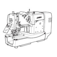
JUKI LBH-1700 Engineer's Manual (126 pages)
Electronic Buttonholing Machine
Brand:
JUKI
| Category:
Sewing Machine
| Size: 1.21 MB
Table of Contents
Table of Contents
3
1 Specifications
5
2 Standard Adjustment
6
Height of the Needle Bar
6
Needle-To-Hook Timing
6
Needle Rocking Timing
8
Height of the Needle Bar Rocking Rod (Adjusting the Reference of Needle Bar Rocking Components)
8
Adjusting the Stitch Width PM Arm and Backlashes of the Stitch Base Line and Stitch Width Gears
10
Detecting the Origin of the Stitch Base Line Stepping Motor
10
Detecting the Origin of the Stitch Width Stepping Motor
12
Backlash of the Feed Gear
12
Longitudinal Position of the Presser and the Feed Shaft
14
Knife Drop Position
14
Knife Bar/Position of the Knife Installing Base/Knife Bar Stroke
16
Knife Detector Sensor
18
Position of the Starting Safety Arm
20
Adjusting the Starting Safety Hook
20
Adjusting the Starting Sensor
22
Adjusting the Needle Thread Trimmer Control Lever
24
Adjusting the Stop-Motion Solenoid
24
Stroke of the Stop-Motion Solenoid
26
Longitudinal Amount of the Needle Thread Trimmer
26
Lateral Position of the Needle Thread Trimmer
28
Height of the Needle Thread Trimmer
28
Position of Winding the Needle Thread at the Start of Sewing
30
Opening Timing of the Needle Thread Trimmer
30
Spring Pressure of the Needle Thread Trimmer
32
Adjusting the Needle Thread Trimmer Lever
32
Position of the Bobbin Thread Trimmer/Position of Bobbin Thread Clamp Plate
34
Timing to Open the Bobbin Thread Trimmer and the Opening Amount / Adjusting the Bobbin Winder Trip Latch
34
Height of the Presser
36
Adjusting the Thread Tension Solenoid
36
Adjusting the Safety Switch
38
Adjusting the Bobbin Winder
38
Adjusting the Thread Breakage Detecting Plate
40
Adjusting the Presser Lifting Solenoid
40
Adjusting the Presser Lifting Air Cylinder
42
Adjusting the Presser Fall Detecting Plate
42
3 Disassembling/Assembling Procedure
44
Disassembling/Assembling the Hook Driving Shaft
44
Disassembling/Assembling the Main Shaft
46
Adjusting the Timing Belt Tension
48
4 Adjustment of the Origin Sensor
50
Adjusting Procedure of the Upper Detecting Plate
50
Adjusting Procedure of Stepping Motor Origin
51
5 Lubrication Mechanism
53
Lubrication
53
Lubricating the Respective Components
53
Adjusting the Amount of Oil
54
Lubricating Other Components
54
6 Description of Operation Panel
56
Sewing Data
58
Sewing Data List
58
Making the Radial Flow Bar-Tacking Shape
62
Sewing Data Initial Value Table
63
Sewing Data Initial Value Table (Change Not Possible)
64
7 Memory Switch
65
How to Use the Memory Switch
65
Memory Switch List
66
How to Set the Memory Switch
67
DIP Switches on the SDC Circuit Board
76
8 Test Mode
77
How to Use the Test Mode
77
9 Error Display List
78
10 Troubles and Corrective Measures
84
With Regard to Sewing
84
Woth Regard to Mechanical Components
93
With Regard to Electrical Components
96
11 Circuit Diagram
108
12 Optional Parts
120
Table of the Optional Parts
120
Thread Tension VR (Variable Resistor)
120
13 Others
121
How to Remodel the Presser to the Type 4 Presser
121
Points of Replacing the Presser with that of 60 MM or 70 MM
122
14 Drawing of the Table
125
JUKI LBH-1700 Manual (126 pages)
Brand:
JUKI
| Category:
Sewing Machine
| Size: 1.24 MB
Table of Contents
Specifications
1
Standard Adjustment
2
Height of the Needle Bar
2
Needle-To-Hook Timing
2
Needle Rocking Timing
4
Height of the Needle Bar Rocking Rod (Adjusting the Reference of Needle Bar Rocking Components)
4
Adjusting the Stitch Width PM Arm and Backlashes of the Stitch Base Line and Stitch Width Gears
6
Detecting the Origin of the Stitch Base Line Stepping Motor
6
Detecting the Origin of the Stitch Width Stepping Motor
8
Backlash of the Feed Gear
8
Longitudinal Position of the Presser and the Feed Shaft
10
Knife Drop Position
10
Knife Bar/Position of the Knife Installing Base/Knife Bar Stroke
12
Knife Detector Sensor
14
Position of the Starting Safety Arm
16
Adjusting the Starting Safety Hook
16
Adjusting the Starting Sensor
18
Adjusting the Needle Thread Trimmer Control Lever
20
Adjusting the Stop-Motion Solenoid
20
Stroke of the Stop-Motion Solenoid
22
Longitudinal Amount of the Needle Thread Trimmer
22
Lateral Position of the Needle Thread Trimmer
24
Height of the Needle Thread Trimmer
24
Position of Winding the Needle Thread at the Start of Sewing
26
Opening Timing of the Needle Thread Trimmer
26
Spring Pressure of the Needle Thread Trimmer
28
Adjusting the Needle Thread Trimmer Lever
28
Position of the Bobbin Thread Trimmer/Position of Bobbin Thread Clamp Plate
30
Timing to Open the Bobbin Thread Trimmer and the Opening Amount / Adjusting the Bobbin Winder Trip Latch
30
Height of the Presser
32
Adjusting the Thread Tension Solenoid
32
Adjusting the Safety Switch
34
Adjusting the Bobbin Winder
34
Adjusting the Thread Breakage Detecting Plate
36
Adjusting the Presser Lifting Solenoid
36
Adjusting the Presser Lifting Air Cylinder
38
Adjusting the Presser Fall Detecting Plate
38
Disassembling/Assembling Procedure
40
Disassembling/Assembling the Hook Driving Shaft
40
Disassembling/Assembling the Main Shaft
42
Adjusting the Timing Belt Tension
44
Adjustment of the Origin Sensor
46
Adjusting Procedure of the Upper Detecting Plate
46
Adjusting Procedure of Stepping Motor Origin
47
Lubrication Mechanism
49
Lubrication
49
Lubricating the Respective Components
49
Adjusting the Amount of Oil
50
Lubricating Other Components
50
Description of Operation Panel
52
Sewing Data
54
Sewing Data List
54
Making the Radial Flow Bar-Tacking Shape
58
Sewing Data Initial Value Table
59
Sewing Data Initial Value Table (Change Not Possible)
60
Memory Switch
61
How to Use the Memory Switch
61
Memory Switch List
62
How to Set the Memory Switch
63
DIP Switches on the SDC Circuit Board
72
Test Mode
73
How to Use the Test Mode
73
Error Display List
74
Troubles and Corrective Measures
80
With Regard to Sewing
80
Woth Regard to Mechanical Components
89
With Regard to Electrical Components
92
Circuit Diagram
104
Optional Parts
116
Table of the Optional Parts
116
Thread Tension VR (Variable Resistor)
116
Others
117
How to Remodel the Presser to the Type 4 Presser
117
Points of Replacing the Presser with that of 60 MM or 70 MM
118
Drawing of the Table
121
Advertisement
JUKI LBH-1700 Instruction Manual (6 pages)
Brand:
JUKI
| Category:
Sewing Machine
| Size: 0.2 MB
Advertisement
Related Products
JUKI LBH-1790 Series
JUKI LBH-1790A Series
JUKI LBH-1795A
JUKI LBH-1790S
JUKI LBH-1790AN
JUKI LBH-1795AN
JUKI LBH-1702
JUKI LBH-1790S-S
JUKI LBH-773NV-1
JUKI LBH-773NB-1
JUKI Categories
Sewing Machine
Industrial Equipment
Sewing Machine Accessories
Accessories
Printer
More JUKI Manuals
Login
Sign In
OR
Sign in with Facebook
Sign in with Google
Upload manual
Upload from disk
Upload from URL