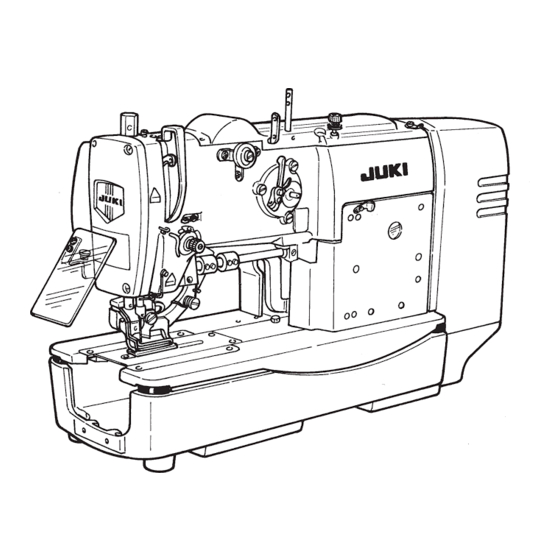
JUKI LBH-1700 Series Engineer's Manual
Electronic buttonholing machine
Hide thumbs
Also See for LBH-1700 Series:
- Handbook (272 pages) ,
- Instruction manual (6 pages) ,
- Manual (126 pages)

Related Manuals for JUKI LBH-1700 Series


Summary of Contents for JUKI LBH-1700 Series
- Page 1 Electronic Buttonholing Machine LBH-1700 Series ENGINEER’S MANUAL 29339504 No.04...
- Page 2 PREFACE This Engineer’s Manual is written for the technical personnel who are responsible for the service and maintenance of the machine. The Instruction Manual for these machines intended for the maintenance personnel and operators at an apparel factory contains operating instructions in detail. And this manual describes “Standard Adjustment”, “Adjustment Procedures”, “Results of Improper Adjustment”, and other important information which are not covered by the Instruction Manual.
-
Page 3: Table Of Contents
CONTENTS 1. SPECIFICATIONS ..................... 1 2. STANDARD ADJUSTMENT ................2 (1) Height of the needle bar ....................2 (2) Needle-to-hook timing ....................2 (3) Needle rocking timing..................... 4 (4) Height of the needle bar rocking rod (adjusting the reference of needle bar rocking components)...................... - Page 4 4. ADJUSTMENT OF THE ORIGIN SENSOR ............ 46 (1) Adjusting procedure of the upper detecting plate ............. 46 (2) Adjusting procedure of stepping motor origin ............47 5. LUBRICATION MECHANISM ................. 49 (1) Lubrication ........................49 (2) Lubricating the respective components..............49 (3) Adjusting the amount of oil ..................
-
Page 5: Specifications
Export : 1ø 100 to 240V 1ø 220 to 415V 3ø 200 to 240V 3ø 220 to 415V Motor Compact AC servo motor 450W Direct-drive method Lubrication method Automatic lubrication method Lubricating oil JUKI New Defrix oil No.1 (Equivalent to ISO VG7) − −... -
Page 6: Standard Adjustment
2. STANDARD ADJUSTMENT Standard Adjustment (1) Height of the needle bar Adjust the height of the needle bar so that the distance from the top surface of the throat plate to the lower end face of the needle bar is 11.9 mm (standard) or 11.4 mm (K) when the needle bar is in the lowest dead point. - Page 7 Adjustment Procedures Results of Improper Adjustment 1. Enter timing gauge 1 supplied with the machine as ™ For the floppy fabrics, it is effective accessories between the throat plate and the lower end of when the needle bar is slightly the needle bar as shown in the figure, loosen the setscrew in lowered than the standard value.
-
Page 8: Needle Rocking Timing
Standard Adjustment (3) Needle rocking timing The engraved marker line on the needle rocking drive large gear is aligned with the center of the hook driving shaft when the needle bar has reached its highest point (needle should complete rocking when the needle comes down and passes the throat plate). - Page 9 Adjustment Procedures Results of Improper Adjustment ™ When the engraved marker line is 1. Adjust the timing by the needle rocking drive pinion. not aligned, needle sways to cause <How to check after the adjustment> needle breakage, stitch skipping, Place a sheet of paper at the needle entry position, turn the etc.
-
Page 10: Adjusting The Stitch Width Pm Arm And Backlashes Of The Stitch Base Line And Stitch Width Gears
Standard Adjustment (5) Adjusting the stitch width PM arm and backlashes of the stitch base line and stitch width gears a) When the stitch width is “0” mm, the clearance provided between the frame and the stitch width PM arm is 1 mm. - Page 11 Adjustment Procedures Results of Improper Adjustment ™ If the clearance is smaller than the a) 1. Turn the hand pulley to bring the needle bar rocking cam to the stitch base line side, and confirm the “0” position (center s p e c i f i e d v a l u e , w h e n of the needle hole) of the stitch base line.
-
Page 12: Detecting The Origin Of The Stitch Width Stepping Motor
Standard Adjustment (7) Detecting the origin of the stitch width stepping motor When the needle bar rocking cam is located on the stitch base line side and the needle enters in the center of the needle hole in the throat plate (when stitch width amount is “0” mm), the stitch width origin sensor should detect the origin detecting plate. - Page 13 Adjustment Procedures Results of Improper Adjustment ™ Loosen the setscrews in the origin detecting plate to adjudst ™ When the needle is on the right side the plate. from the center of the needle hole, How to check stitches are increased and the •...
-
Page 14: Longitudinal Position Of The Presser And The Feed Shaft
Standard Adjustment (9) Longitudinal position of the presser and the feed shaft ™ Distance from the center of the needle hole in the throat plate to the end face of the presser is 2.5 ± 0.3 mm (when the feed origin is detected). ™... - Page 15 Adjustment Procedures Results of Improper Adjustment ™ If the position of the presser is 1. Tighten the setscrews so that the distance from the presser to the needle hole is 2.5 mm and so that the feed shaft protrudes improper (longitudinal position of by 5 mm from the feed shaft bushing.
-
Page 16: Knife Bar/Position Of The Knife Installing Base/Knife Bar Stroke
Standard Adjustment (11) Knife bar/position of the knife installing base/knife bar stroke a) Clearance provided between the cloth cutting knife and the needle bar is 0.4 to 0.6 mm. b) When the knife bar is at the stop position, the distance from the jaw section of the machine arm to the top end of the concave of the knife bar is 0 to 1 mm. - Page 17 Adjustment Procedures Results of Improper Adjustment ™ If the distance from the cloth cutting a) Lower the needle bar, loosen the knife installing base setscrews, and move the knife installing base to the right or knife to the needle bar is smaller left to adjust the clearance.
-
Page 18: Knife Detector Sensor
Standard Adjustment (12) Knife detector sensor 6 Knife detector sensor 5 Pin 3 Knife detector sensor 1 Screws 2 Screw installing base 4 Origin detecting plate − −... - Page 19 Adjustment Procedures Results of Improper Adjustment Adjust and fix knife detector sensor installing base 3 and origin detecting plate 4 with screws 1 and 2 so that the detecting plate enters upper/lower, right/left and center sections of the sensor detecting section when the knife bar returns to the upper side.
-
Page 20: Position Of The Starting Safety Arm
Standard Adjustment (13) Position of the starting safety arm Clearance provided between the starting safety arm and the presser bar lever is 0.3 to 0.8 mm. Starting safety hook Stopper 0.3 to 0.8 mm (14) Adjusting the starting safety hook Starting sensor plate Starting safety lever Starting sensor... - Page 21 Adjustment Procedures Results of Improper Adjustment ™ When there is no clearance Loosen the nut and adjust the position of the stopper so that the clearance provided between the starting safety arm and the between the starting safety arm and presser bar lever is 0.3 to 0.8 mm.
-
Page 22: Adjusting The Starting Sensor
Standard Adjustment (15) Adjusting the starting sensor 5 Starting sensor 4 Starting safety lever 1 Starting 2 Screws sensor 3 Starting safety plate solenoid base − −... - Page 23 Adjustment Procedures Results of Improper Adjustment Adjust and fix with screws 2 so that starting sensor plate 1 enters in the center of the detecting section of starting sensor 5 when the starting has functioned. The dimension from starting sensor 5 to the bottom end of starting sensor plate 1 is 1 to 3 Caution : Make sure that starting sensor plate 1 does not come in contact with starting sensor 5 when starting has functioned.
-
Page 24: Adjusting The Needle Thread Trimmer Control Lever
Standard Adjustment (16) Adjusting the needle thread trimmer control lever Clearance provided between the needle thread trimmer control lever and the needle thread trimmer arm, rear is “0” mm when the starting safety hook engages with the starting lever. Needle thread Needle thread trimmer Starting safety lever trimmer arm, rear... - Page 25 Adjustment Procedures Results of Improper Adjustment ™ If the pressing amount is large, the Lightly press the needle thread trimmer control lever to the needle thread trimmer arm, rear (pressing in the direction of f) in the needle thread trimmer control lever state that the starting safety hook engages with the starting lever is deflected and the pedal becomes and fix it with two setscrews.
-
Page 26: Stroke Of The Stop-Motion Solenoid
Standard Adjustment (18) Stroke of the stop-motion solenoid Stroke of the stop-motion solenoid is 8 ± 0.5 mm. (7.5 to 8.5 mm) 8 ± 0.5 mm (19) Longitudinal amount of the needle thread trimmer Longitudinal amount : 4 to 5 mm Setscrew Inc. - Page 27 Adjustment Procedures Results of Improper Adjustment ™ Adjust the amount of the stroke by moving the stop-motion ™ If the stroke is small, the starting bar and the nut. safety lever cannot be lifted up at the stop-motion, and the presser does not go up even when the stop- motion has functioned.
-
Page 28: Lateral Position Of The Needle Thread Trimmer
Standard Adjustment (20) Lateral position of the needle thread trimmer 1) Adjust the position so that when the needle thread trimmer has advanced most, it is aligned with the center of the needle and the top end of the trimmer comes out to the right by 4 to 6 mm from the center of the knife groove. - Page 29 Adjustment Procedures Results of Improper Adjustment ™ If the longitudinal or lateral position 1. Depress the presser lifting pedal, loosen the setscrew in the needle thread trimmer arm (front) with hexagonal wrenck key is improper, the needle thread when the needle thread trimmer has advanced most, and trimmer is caught with the presser adjust the longitudinal and lateral positions of the needle bar lifting lever and may not move...
-
Page 30: Position Of Winding The Needle Thread At The Start Of Sewing
Standard Adjustment (22) Position of winding the needle thread at the start of sewing Position where the top end of the needle thread trimmer is located on the right side by 2 ± 1 mm (1 to 3 mm) from the center of the knife groove at the start of sewing 2 ±... - Page 31 Adjustment Procedures Results of Improper Adjustment ™ When the locking bracket latch is Adjust the position by increasing or decreasing the number of pieces of the needle thread trimmer locking bracket latch spacer located excessively to the right ----- (B2023761000). - needle thread protrudes on the right side of stitches.
-
Page 32: Spring Pressure Of The Needle Thread Trimmer
Standard Adjustment (24) Spring pressure of the needle thread trimmer Upper knife Lower knife Thread presser spring (25) Adjusting the needle thread trimmer lever Needle thread Needle thread trimmer trimmer lever driving cam Needle thread trimmer arm (rear) 1 mm Needle thread trimmer locking bracket latch... - Page 33 Adjustment Procedures Results of Improper Adjustment ™ If the pressure of the thread presser 1. When the thread grasping force of the needle thread trimmer has reduced, slightly bend the top end of the thread presser spring is low, slip-off of thread at the spring so that it comes in contact with the thread trimming start of sewing will occur.
-
Page 34: Position Of The Bobbin Thread Trimmer/Position Of Bobbin Thread Clamp Plate
Standard Adjustment (26) Position of the bobbin thread trimmer/position of bobbin thread clamp plate Bobbin thread trimmer Needle hole Knife groove 2 to 3 mm Bobbin thread clamp plate setscrews Bobbin thread trimmer link Bobbin thread clamp plate Bobbin thread trimmer link rod 0.3 to 1 mm Bobbin thread trimmer link rod setscrew ™... - Page 35 Adjustment Procedures Results of Improper Adjustment 1. Loosen the setscrew in the bobbin thread trimmer link rod in ™ When the distance from the bobbin the state that the presser lifting lever has returned, turn the thread trimmer to the knife groove bobbin thread trimmer link rod and adjust the distance from is excessively large, the trimmer the bobbin thread trimmer to the center of the knife groove to...
-
Page 36: Height Of The Presser
Standard Adjustment (28) Height of the presser Lifting amount of the presser is 12 mm. Presser bar position bracket setscrew Presser bar position bracket Slide roller installing base 12 mm (29) Adjusting the thread tension solenoid Top end of the thread tension solenoid shaft should be almost aligned with the work face of the machine arm when the thread tension disk closes. - Page 37 Adjustment Procedures Results of Improper Adjustment ™ If the presser lifting amount is Place an appropriate round wood of 12 mm in height between the presser and the throat plate, loosen the setscrew in the excessively increased, the presser presser bar position bracket, press down the presser bar position starts going up before the bobbin bracket and the slide roller installing base while fully depressing thread is trimmed.
-
Page 38: Adjusting The Safety Switch
Standard Adjustment (30) Adjusting the safety switch Safety switch push plate Safety switch installing base (31) Adjusting the bobbin winder Bobbin winder driving wheel Main shaft Rubber ring 0.7 to 1.0 mm Bobbin winder − −... - Page 39 Adjustment Procedures Results of Improper Adjustment ™ If the clearance is small, the safety Fix the safety switch base so that a clearance of 0 to 5 mm is provided between the safety switch installing base and the safety switch push plate may be damaged. ™...
-
Page 40: Adjusting The Thread Breakage Detecting Plate
Standard Adjustment (32) Adjusting the thread breakage detecting plate (33) Adjusting the presser lifting solenoid When clearance is large When clearance is small (small stroke) (large stroke) 0.5 to 1 mm − −... - Page 41 Adjustment Procedures Results of Improper Adjustment 1. Adjust so that thread breakage detecting plate 1 comes in ™ If the detecting plate does not come contact with thread take-up spring 2 without fail when the in contact with the spring, the needle machine head is not threaded.
-
Page 42: Adjusting The Presser Lifting Air Cylinder
Standard Adjustment (34) Adjusting the presser lifting air cylinder Thickness of table (40 mm) 0 mm To lightly come in (11 mm) contact with each other (35) Adjusting the presser fall detecting plate Presser fall detecting sensor Presser fall detecting plate 1 ±... - Page 43 Adjustment Procedures Results of Improper Adjustment 1. Adjust stroke adjusting nut 3 so that the chain slightly ™ If the adjustment of the speed slackens in the state that presser lifting lever 1 has been controller is not completed, presser lifting lever 1 comes strongly in litted.
-
Page 44: Disassembling/Assembling Procedure
3. DISASSEMBLING/ASSEMBLING PROCEDURE Standard Adjustment (1) Disassembling/assembling the hook driving shaft Hand pulley Bearing bush Setscrew Sprocket 0.5 mm Hook sleeve Pinion Hook driving shaft bearing Timing belt Hook driving shaft rear bearing bush 20 mm -Removing procedure of the hook driving shaft- -Assembling procedure of the hook driving shaft- 1. - Page 45 Adjustment Procedures Results of Improper Adjustment ™ Make sure whether there is any play in the hook driving shaft ™ When drawing out the hook driving before stretching the timing belt. shaft, take care so that the hook ™ When inserting the hook driving shaft into the pinion, adjust driving shaft intermediate bearing is so that the screw No.
-
Page 46: Disassembling/Assembling The Main Shaft
Standard Adjustment (2) Disassembling/assembling the main shaft Main shaft front bushing Main motor installing base Main shaft intermediate bushing Main motor Timing belt -Removing procedure of the main shaft- -Assembling procedure of the main shaft- 1. Loosen two setscrews in coupling 7. (Main shaft 1. - Page 47 Adjustment Procedures Results of Improper Adjustment ™ When fixing two setscrews in coupling 7, deoil the setscrews ™ When drawing out the main shaft from using a paint thinner and fix them with LOCKTITE 242. the front, remove the components ™...
-
Page 48: Adjusting The Timing Belt Tension
Standard Adjustment (3) Adjusting the timing belt tension Timing belt driving the hook driving shaft determines the tension with the tension spring. (Standard initial tension of the timing belt : 70N to 80N) Tension spring Main shaft Idler fixing screw 2 Idler fulcrum hinge screw 1 Idler pulley Driving shaft... - Page 49 Adjustment Procedures Results of Improper Adjustment ™ When loosening the timing belt, loosen 1 and 2, press the ™ If the timing belt tension is low, the timing belt with fingers in the direction of (e mark), tighten 1 belt runs around and may interfere in the state that the belt is slack, and fix with 2.
-
Page 50: Adjustment Of The Origin Sensor
4. ADJUSTMENT OF THE ORIGIN SENSOR (1) Adjusting procedure of the upper detecting plate ] key 1, turn ON the power to 1. Pressing [Right set the test mode. (Refer to page 73 as well.) ] key 2 to display 2. 2. -
Page 51: Adjusting Procedure Of Stepping Motor Origin
(2) Adjusting procedure of stepping motor origin 1) Entering procedure to the origin compensation mode ] key 1, turn ON the power. 1. Pressing [Right 2. Select 51, 52 and 53 of the numerals on the left ] key 2 and make sure that side with [Left the numeral on the right side is “0”. - Page 52 3) Stitch base line (left side : 52) ] key 2. 1. Select 52 with [Left key 4. 2. Press 3. Turn the hand pulley to bring the needle to the lowest point of its stroke on the stitch base line side. 4.
-
Page 53: Lubrication Mechanism
5. LUBRICATION MECHANISM (1) Lubrication Lubrication mechanism of this sewing machine is as shown in the figure below. Flow of oil is shown with the arrow marks in the figure. Oil in oil reservoir 1 is sucked and kept in oil tank 2 once, and lubricated to the necessary places by means of the plunger pump making use of the main shaft. -
Page 54: Adjusting The Amount Of Oil
(3) Adjusting the amount of oil Adjustment of the amount of oil for both lubricating amount and reflux amount is performed through oil pump base !1 . In filter screen !2 of the oil pump base, there are three parts which play an role of the filter, namely, unwoven fabric, oil felt and compression spring. - Page 55 MEMO − −...
-
Page 56: Description Of Operation Panel
6. DESCRIPTION OF OPERATION PANEL READY RESET CLAMP WINDER THREAD PATTERN DATA COUNTER TENSION KNIFE LEFT/BARTACK/RIGHT CLEARANCE WIDTH LENGTH PITCH LEFT/CLEARANCE/RIGHT – FEED ¡ Be sure to perform clamp selection before operation. Table of presser type Type Part No. Type1 B151177 1 000 Type2 B151177 2 000... - Page 57 N A M E D E S C R I P T I O N N A M E D E S C R I P T I O N Sewing LED This LED lights up when the sewing Data key This key selects data display.
-
Page 58: Sewing Data
(1) Sewing data 1) Make sure that sewing LED 1 goes off. key 2 to make (When it lights up, press [Ready] the LED go off.) READY RESET CLAMP WINDER THREAD key 3 to display the pattern 2) Press [Pattern No.] No. - Page 59 Setting item Description Setting range Unit Reinforcement sewing This item performs straight sewing for reinforcement in overedging width. 0 to 9 (off/number of times) 0 : Without function 1 to 9 : Number of times setting Compensation of bar-tacking width, This item compensates the position of right stitch base line of bar-tacking section.
- Page 60 Supplementary explanation to the sewing data list (1) Tie stitching Tie stitching can be set to each pattern to protect the thread from slip-off of needle thread at the start of sewing, thread breakage, fray at the end of sewing, etc. in accordance with the sewing conditions. 1) Start of sewing Tie stitching can be performed at the position of the start of sewing (memory switch No.
- Page 61 (2) Adjusting the timing of needle thread tension The timing to change the needle thread tension can be adjusted. Data No. 31 : 1st bar-tacking at the start Data No. 32 : Stitch width, right at the start Data No. 33 : 2nd bar-tacking at the start Data No.
-
Page 62: Making The Radial Flow Bar-Tacking Shape
(3) Making the radial taper bar shape It is convenient to perform the fine adjustment of the data after inputting data and making stitches referring to the example of setting below. Main data determining the shape of the radial taper bar section are those with ☆ mark. Caution when making the shape Some data with ☆... -
Page 63: Sewing Data Initial Value Table
(4) Sewing data initial value table (Service patter) Purl stitch : depends on cloth cutting knife size. Item Setting Unit Pattern No. range Cloth cutting length 6.0 to 67.0 0.1 mm 6.40 9.50 11.10 12.70 14.30 15.90 17.50 19.10 22.20 25.40 (Corresponding to the inch size knives) (1/4) -
Page 64: Sewing Data Initial Value Table (Change Not Possible)
(5) Sewing data initial value table (Change not possible) Item Setting Unit Pattern No. Pattern No. range Radial Square Radial Radial Round Round Square Semilunar Bar- Radial Eyelet Radial Square Round Square taper bar square Basting type type type type type square type... -
Page 65: Memory Switch
7. MEMORY SWITCH (1) How to use the memory switch Various data can be changed in accordance with each level. For user’s level (U) : pressing [Ready] key 1, turn ON the power, and the mode becomes memory switch mode. For service level (S) : simultaneously pressing [Ready] key 1 and [Clamp] key 2, turn ON the power, and the mode becomes memory switch mode. -
Page 66: Memory Switch List
(2) Memory switch list Setting item Level Setting range Level *2 Unit Initial value Soft-start speed setting 1st stitch 400 to 3600 100 rpm Soft-start speed setting 2nd stitch 400 to 3600 100 rpm Soft-start speed setting 3rd stitch 400 to 3600 100 rpm 2000 Soft-start speed setting 4th stitch... -
Page 67: How To Set The Memory Switch
(3) How to set the memory switch 1) How to set the soft-start speed (Memory switch Nos. 1 to 5) Number of revolution of the sewing machine from 1st stitch to 5th stitch can be set per stitch. No. 1 : Number of revolution of 1st stitch No. - Page 68 4) Display selection (Memory switch No. 10) When displaying the pattern No., the following items can be displayed by the 4 digits on the right side. 0 : No display 1 : Counter value 2 : Cloth cutting length (Data No. 1) 3 : Number of stitches Example) 2 : When the cloth cutting length is selected : 1 2.
- Page 69 6) Presser lifting solenoid lifting speed setting (Memory switch No. 12) (Standard set value) Setting of lifting speed of the auto-lifter solenoid can be changed. 0 : Slow ↓ 18 : Fast 7) Presser position selection of the auto-lifter (Memory switch Nos. 13 and 14) This switch sets UP/DOWN position of presser after each action is completed.
- Page 70 9) ACTVR function (Memory switch No. 17) This function is used when performing fine adjudstment of tension at parallel section or bar-tacking section using the optional tension variable resistor. 0 : Ineffective 1 : Effective Range of fine adjustment : ±50 for the set value on the panel Tension at parallel section : ±20 for the set value on the panel Tension at bar-tacking section...
- Page 71 12) Cloth cutting knife plural action setting (Memory switch Nos. 21 and 22) When you desire to make a buttonhole larger than the knife size actually installed, you can make it by means of plural actions of the knife. No. 21 : Cloth cutting knife size 4 0.
- Page 72 15) Basting function (Memory switch Nos. 35 and 36) This switch sets the pitch and number of revolution when performing basting in advance before performing overedging. No. 35 : Bast ring pitch Pitch at the time of basting is set. No.
- Page 73 19) Pattern data register deletion function (Memory switch No. 43) This switch is set when deleting the pattern data which has been registered. 0 : Without 1 : With How to delete the data 1. Set the memory switch No. 43 to “1 : With”. 2.
- Page 74 23) Cloth cutting knife (solenoid) motion time (Memory switch No. 24) This switch can change the length of time during which the cloth cutting knife solenoid is held ON. (SA and SB types) 24) Cloth cutting knife (cylinder) motion time (Memory switch No. 25) This switch can change the length of time during which the cloth cutting knife cylinder is held ON.
- Page 75 30) Compensation of basting needle entry position (Memory switch No. 33) 1. 5 This switch is used when the needle entry position after second circuit is desired to be slipped at the time of basting. 31) Prohibiting function of presser type selection (Memory switch No. 45) This switch is used when the selection of presser type is desired to be prohibited on the panel.
-
Page 76: Dip Switches On The Sdc Circuit Board
(4) DIP switches on the SDC circuit board DIP switchwes on the SDC circuit board are described in the table below. Use the SDC circuit board with the following settings when LBH-1700 is used since the board is common to the other models. -
Page 77: Test Mode
8. TEST MODE (1) How to use the test mode Input check of the various sensors can be performed. ] key 1, turn ON the power. 1) Pressing [Right READY RESET CLAMP WINDER THREAD ] key 2. (No. 1 to 3) 2) Select the sensor No. -
Page 78: Error Display List
9. ERROR DISPLAY LIST Error No. is displayed in the display when an error has occurred. Description How to recover/supposed cause Servo motor error Turn OFF the power. • When error is output from servo motor circuit board. LED on servo motor circuit board flashes on and off when an error has occurred. - Page 79 Description How to recover/supposed cause Er13 Cloth cutting knife motion error Possible to re-start after pressing reset key/improper adjustment. • When cloth cutting knife return detection switch signal does not change within 500 ms after turning ON cloth cutting knife solenoid or cylinder.
- Page 80 Description How to recover/supposed cause Er19 Bar-tacking compensation error Re-input the data after releasing error • When stitch width, right + right knife groove width + right bar-tacking with reset key. width compensation or stitch width, left + left knife groove width + left bar-tacking width compensation exceeds 1/2 of presser size.
- Page 81 ☆ When an error (Er14, 18, 19, 30) has occurred by data setting, refer to the table below and re-input the data. [With regard to input data] Shape No. 0 : Square type No. 1 : Radial type 1 Stitch width 1 Stitch width Data No.
- Page 82 [With regard to input data] Shape No. 6 : Radial straight bar Shape No. 7 : Bar-tacking 1 Stitch width 1 Cloth cut length Data No. 4 Data No. 1 2 Knife groove width, left 2 Bar-tacking width Data No. 3 Data No.
- Page 83 [With regard to input data] Shape No. 10 : Eyelet radial type Shape No. 11 : Eyelet flow bar-tacking type 1 Stitch width 1 Stitch width Data No. 4 Data No. 4 2 Knife groove width, left 2 Knife groove width, left Data No.
-
Page 84: Troubles And Corrective Measures
− 80 −... - Page 85 − 81 −...
- Page 86 − 82 −...
- Page 87 − 83 −...
- Page 88 − 84 −...
- Page 89 − 85 −...
- Page 90 − 86 −...
- Page 91 − 87 −...
- Page 92 − 88 −...
-
Page 93: Woth Regard To Mechanical Components
− 89 −... - Page 94 − 90 −...
- Page 95 − 91 −...
-
Page 96: With Regard To Electrical Components
− 92 −... - Page 97 − 93 −...
- Page 98 − 94 −...
- Page 99 − 95 −...
- Page 100 − 96 −...
- Page 101 − 97 −...
- Page 102 − 98 −...
- Page 103 − 99 −...
- Page 104 − 100 −...
- Page 105 − 101 −...
- Page 106 − 102 −...
- Page 107 − 103 −...
-
Page 108: Circuit Diagram
11. CIRCUIT DIAGRAM (BLOCK DIAGRAM 100 to 240V) − −... - Page 109 Part No. Name of part Remarks Part No. Name of part Remarks M1001600AA0 Control box A asm. HD00057000A Stitch base line origin sensor M8601600AA0B MAIN circuit board A asm. 4M ROM C.B. M85116000A0 Presser fall cord asm. For SB, SC M8601600AA0A MAIN circuit board A asm.
- Page 110 BLOCK DIAGRAM 220 to 415V − −...
- Page 111 Part No. Name of part Remarks Part No. Name of part Remarks M1001600BA0 Control box B asm. HD00057000A Stitch base line origin sensor M8601600AA0B MAIN circuit board A asm. 4M ROM C.B. M85116000A0 Presser fall cord asm. For SB, SC M8601600AA0A MAIN circuit board A asm.
- Page 112 POWER CIRCUIT DIAGRAM 100 to 240V − −...
- Page 113 POWER CIRCUIT DIAGRAM 220 to 415V − −...
- Page 114 SERVO MOTOR CIRCUIT DIAGRAM − −...
- Page 115 STEPPING MOTOR CIRCUIT DIAGRAM − −...
- Page 116 SOLENOID CIRCUIT DIAGRAM − −...
- Page 117 HEAD SENSOR CIRCUIT DIAGRAM − −...
- Page 118 PEDAL SWITCH CIRCUIT DIAGRAM 1-PEDAL TYPE WHITE PRESSER BLACK GREEN YELLOW START BROWN SEWING MACHINE FOR STANDING WORK BLACK BLACK PRESSER BLACK START BLACK − −...
- Page 119 STARTING SWITCH CIRCUIT DIAGRAM 2-PEDAL TYPE WHITE START BLACK SOLENOID VALVE CIRCUIT DIAGRAM +24V WHITE BLACK CLOTH CLOTH CUTTING KNIFE BLACK CUTTING +24V KNIFE GREEN BLACK PRESSER LIFTER +24V +24V PRESSER LIFTER THREAD TENSION VR CIRCUIT DIAGRAM WHITE PARALLE BLACK PARALLEL SECTION YELLOW...
-
Page 120: Optional Parts
12. OPTIONAL PARTS (1) Table of the optional parts Name of optional part Part No. Remarks Thread tension VR (Variable resistor) Set part No. : M85256000B0 M85256000A0 M3002600000 HX001420000 Electric type bobbin winder G50011980A0A M85246000A0 B32217710A0 SK3452000SC X 4 Pedal for standing work GPK510010B0 (2-pedal type) M90135900A0... -
Page 121: Others
13. OTHERS (1) How to remodel the presser to the type 4 presser [Table of the parts required] Part No. Name of part B1513774000 Work clamp bracket B1551784000 Work clamp B15117740A0 Work clamp check holder asm. B1552784000 Presser SD0790202SP Hinge screw B1613774000 Work clamp carrier PS0300102K0... -
Page 122: Points Of Replacing The Presser With That Of 60 Mm Or 70 Mm
(2) Points of replacing the presser with that of 60 mm or 70 mm 9 !0 !2 !3 !4 !5 Part No. Name of part Q’ty Remarks 14523062 Feed 70 mm set For max. sewing length 70 mm 14523864 Feed 60 mm set For max. - Page 123 1) Replacing and assembling procedure of the parts 1. Connect work clamp 60 asm. 3 or work clamp 70 asm. 4 and the presser with presser installing plate spring setscrews 5. 2. Remove the needle and the cloth cutting knife from the sewing machine. 3.
- Page 124 − −...
-
Page 125: Drawing Of The Table
14. DRAWING OF THE TABLE 1130 Drilled hole 40 Drilled hole 17 Oil drain funnel installing hole 2 drilled hole 10 on the bottom surface Installing position of stopper for drawer 4-2 drilled hole depth 10 (bottom surface) Stand installing hole 30 drilled hole 51 depth facing depth 5 4-7 drilled hole 20 V groove cut When installing presser lifting solenoid... - Page 126 * The description covered in this engineer's manual is subject to change for improvement of the TELEX : J22967 commodity without notice. Copyright c 1999-2001 JUKI CORPORATION. All rights reserved throughout the world. 01 · 09 Printed in Japan (E)
Need help?
Do you have a question about the LBH-1700 Series and is the answer not in the manual?
Questions and answers