Sign In
Upload
Manuals
Brands
JLG Manuals
Boom Lifts
M4069
JLG M4069 Manuals
Manuals and User Guides for JLG M4069. We have
6
JLG M4069 manuals available for free PDF download: Service And Maintenance Manual, Service Maintenance Manual, Operation And Safety Manual
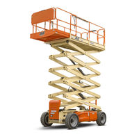
JLG M4069 Service And Maintenance Manual (158 pages)
Brand:
JLG
| Category:
Scissor Lifts
| Size: 16.45 MB
Table of Contents
Table of Contents
5
Specifications
14
Component Data
15
Dimensional Data
15
Battery Charger
15
Batteries
15
Drive System
15
Steer System
15
Hydraulic Pump/Electric Motor Assembly
15
Tires
16
Engine (Generator)
16
Capacities
17
Pressure Settings
17
Torque Specifications
17
Cylinder Specifications
17
Major Component Weights
17
Critical Stability Weights
17
Lubrication
18
Lubrication Specifications
18
Serial Number Locations
20
Thread Locking Compound
21
Torque Charts
22
SAE Fastener Torque Chart
22
SAE Fastener Torque Chart (Continued)
23
SAE Fastener Torque Chart (Continued)
25
SAE Fastener Torque Chart (Continued)
27
Metric Fastener Torque Chart
28
Metric Fastener Torque Chart (Continued)
29
Metric Fastener Torque Chart (Continued)
31
General
32
Machine Preparation, Inspection, and Maintenance
32
Preparation, Inspection and Maintenance
32
Pre-Start Inspection
32
Pre-Delivery Inspection and Frequent Inspection
32
Annual Machine Inspection
32
Preventative Maintenance
32
Service and Guidelines
33
General
33
Safety and Workmanship
33
Cleanliness
33
Components Removal and Installation
33
Component Disassembly and Reassembly
34
Pressure-Fit Parts
34
Bearings
34
Gaskets
34
Bolt Usage and Torque Application
34
Hydraulic Lines and Electrical Wiring
34
Hydraulic System
34
Lubrication
34
Battery
34
Lubrication and Servicing
34
Hydraulic Oil
35
Changing Hydraulic Oil
35
Lubrication Specifications
35
Cylinder Drift Test
35
Platform Drift
35
Cylinder Drift
35
Pins and Composite Bearing Repair Guidelines
36
Preventive Maintenance and Inspection Schedule
36
Chassis & Scissor Arms
41
Calibrations
41
Elevation Sensor Calibration
41
Speed Sensor
41
Tilt Sensor Calibration
41
Joystick Calibration
42
Tilt Sensor
43
Tilt Sensor, JLG PN 4000021
43
Battery Maintenance and Charging
44
Battery Maintenance, Quarterly
44
Optional On-Board Generator
44
Battery Charging (on Board Charger) (MAC)
44
Charging Sequence of Remote LED Card
45
Battery Charger (Delta-Q)
46
Battery Charger Maintenance
47
Battery Charger Troubleshooting
47
Battery Temperature Sensor
50
Removing the Battery Box
51
Generator
52
Timing Sequences
54
Alarms and Fault Flash Codes
56
Output Current and Voltage Settings
57
Priming the Fuel Line
57
Supplementary Fuse for APU
58
Tools and Material
58
Procedure
58
Joystick Controller
60
Power Controller
62
Towing
62
Disengaging for Towing
62
Engaging after Towing Is Complete
63
Drive Hub
65
Disassembly
65
Disassembly of Cover Unit (8)
65
Disassembly of First Stage Planetary Assembly
65
Disassembly of the Second Stage Planet Gears (1)
65
Drive Brake - MICO
67
Disassembly
67
Assembly
67
Bleeding
67
Torque Hub
68
Roll Test
69
Leak Test (Main Unit)
69
Tightening and Torquing Bolts
69
Main Disassembly
70
Output Carrier Disassembly
72
Input Carrier Disassembly
73
Hub-Spindle Disassembly
74
Cover Disassembly
75
Input Carrier Sub-Assembly
76
Output Carrier Sub-Assembly
77
Hub-Spindle Sub-Assembly
78
Cover Sub-Assembly
79
Main Assembly
80
Hydraulics
82
Servicing and Maintenance Guidelines
82
General
82
Safety and Workmanship
82
Cleanliness
82
Component Removal and Installation
82
Component Disassembly and Reassembly
82
Pressure Fit Parts
82
Bearings
82
Gaskets
82
Hydraulic Lines and Electrical Wiring
83
Hydraulic System
83
Lubrication
83
Batteries
83
Lubrication and Servicing
83
Lubrication Information
83
Hydraulic Oil
83
Changing Hydraulic Oil
84
Lubrication Specifications
84
Cylinders - Theory of Operation
84
Valves - Theory of Operation
84
Control Valves
84
Component Functional Description
84
Hydraulic Pump
84
Manual Descent
84
Wear Pads
84
Motor Controller - Modes of Operation
85
Traction Motor (Drive)
85
Pump Motor (Lift)
85
Features
85
Traction Mode
85
Cylinder Checking Procedures
85
Cylinder Without Counterbalance Valves (Steer)
85
Cylinders with Single Counterbalance Valve (Lift Cylinder)
86
Cylinders with Duel Counterbalance Valves (Oscillating Cylinders)
86
Cylinder Removal and Installation
86
Lift Cylinder Removal
86
Lift Cylinder Installation
87
Cylinder Repair
87
Disassembly
87
Cleaning and Inspection
88
Assembly
89
Steer Cylinder Removal
91
Oscillation Cylinder Bleeding
91
Bleeding Procedure
91
Checking Oscillation Cylinders
91
Oscillating AXLE - Lockout Cylinder Test (if Equipped)
92
Left Side Wheel Test
92
Right Side Wheel Test
92
Cylinder Assemblies
93
Pressure Setting Procedures
98
Main Relief at Pump
98
Lift Relief
98
Steer Relief
98
Drive Torque Hub
99
Disassembly
99
Assembly
100
Drive Assist Valve
101
Jlg Control System
103
Hand Held Analyzer
103
To Connect the Hand Held Analyzer
103
Using the Analyzer
104
Changing the Access Level of the Hand Held Analyzer
105
Adjusting Parameters Using the Hand Held Analyzer
106
Machine Setup
106
PC Boards
107
Flash Codes/Dtc's and Descriptions
108
Ground Control Circuit Board
121
Software Version P1.6
121
General Electrical Information & Schematics
126
General
126
Multimeter Basics
126
Grounding
126
Backprobing
126
Min/Max
126
Polarity
126
Scale
126
Voltage Measurement
127
Continuity Measurement
128
Current Measurement
128
Continuity Measurement over Long Distances
129
Requirements
129
Procedure
129
Applying Silicone Dielectric Compound to Amp Connectors
129
Dielectric Grease Application
130
Installation
130
AMP Mate-N-Lok
130
AMP Faston
130
AMP Micro-Fit
130
AMP Mini Fit Jr
130
Mini Fit Sr
131
DIN Connectors
131
Exceptions
131
AMP Connector
132
Assembly
132
Disassembly
135
Wedge Lock
135
Service - Voltage Reading
135
Working with Deutsch Connectors
137
DT/DTP Series Assembly
137
DT/DTP Series Disassembly
137
HD30/HDP20 Series Assembly
138
HD30/HDP20 Series Disassembly
138
Electrical Schematics
143
Advertisement
JLG M4069 Service Maintenance Manual (144 pages)
Brand:
JLG
| Category:
Boom Lifts
| Size: 6.17 MB
Table of Contents
Hydraulic System Safety
3
Maintenance
3
Table of Contents
5
Section 1 - Specifications
9
Specifications
9
Capacities
10
Pressure Settings
10
Component Data
10
Torque Specifications
10
Lubrication
10
Cylinder Specifications
11
Major Component Weights
11
Critical Stability Weights
11
Lubrication
12
Serial Number Locations
13
Torque Charts
14
Torque Chart (SAE Fasteners - Sheet 2 of 7))
15
Torque Chart (SAE Fasteners - Sheet 3 of 7)
16
Torque Chart (SAE Fasteners - Sheet 4 of 7)
17
Torque Chart (METRIC Fasteners - Sheet 5 of 7))
18
Torque Chart (METRIC Fasteners - Sheet 6 of 7)
19
Torque Chart (METRIC Fasteners - Sheet 7 of 7)
20
Section 2 - General
21
Machine Preparation, Inspection, and Maintenance
21
Annual Machine Inspection
21
Preventative Maintenance
21
Service and Guidelines
22
Lubrication and Information
23
Cylinder Drift Test
24
Pins and Composite Bearing Repair Guidelines
25
Preventive Maintenance and Inspection Schedule
25
Preventive Maintenance and Inspection Schedule
26
Section 3 - Chassis & Scissor Arms
27
Calibrations
27
Tilt Sensor
30
Tilt Sensor Location
31
Battery Maintenance and Charging
32
Remote LED Card
33
Delta-Q - Battery Charger Specs
34
Battery Algorithms
37
Batteries and Battery Charger
38
Generator
39
Generator Components
40
RBS Pre Start Sequence
41
Generator System Flash Codes
43
Supplementary Fuse for APU
45
Joystick Controller
47
Joystick Controller - (JLG P/N 1600403)
48
Drive Components
49
Towing
50
Torque Hub
52
Drive Hub
53
Brake Assembly
54
Drive Brake - MICO
55
Torque Hub
56
Bolt Torquing Sequence
57
Hub Main Disassembly
58
Output Carrier Disassembly
60
Input Carrier Disassembly
61
Hub-Spindle Disassembly
62
Cover Disassembly
63
Input Carrier Sub-Assembly
64
Output Carrier Sub-Assembly
65
Hub-Spindle Sub-Assembly
66
Cover Sub-Assembly
67
Hub Main Assembly
68
Section 4 - Hydraulics
71
Servicing and Maintenance Guidelines
71
Component Disassembly and Reassembly
71
Safety and Workmanship
71
Bolt Usage and Torque Application
71
Lubrication Information
72
Cylinders - Theory of Operation
73
Valves - Theory of Operation
73
Component Functional Description
73
Wear Pads
73
Motor Controller - Modes of Operation
73
Features
74
Cylinder Checking Procedures
74
Cylinder Removal and Installation
75
Lift Cylinder Removal
75
Cylinder Repair
76
Oil-Lite Bearing Installation
77
Wiper Seal Installation
78
Rod Assembly Installation
79
Steer Cylinder Removal
80
Oscillation Cylinder Bleeding
80
Cylinder Assemblies
82
Lift Cylinder - 4069LE & M4069
83
Leveling Jack Cylinder - USA Built Machines Prior to S/N 0200104829
86
Steer Cylinder
87
Axle Lockout Cylinder
88
Pressure Setting Procedures
89
Drive Torque Hub
90
Drive Assist Valve
92
Hand Held Analyzer
93
PC Boards
97
Flash Codes/Dtc's and Descriptions
98
Power Module Diagnostic LED Flash Codes
102
Machine Model Adjustment
109
Machine Configuration Programming Information
110
Ground Control Circuit Board
111
J2 Connector
112
J3 Connector
113
J4 Connector
114
J1 Connector
115
J2 Connector
116
J3 Connector
117
J4 Connector
118
General
119
Voltage Measurement (DC)
120
Continuity Measurement
121
Continuity Measurement over Long Distances
122
Applying Silicone Dielectric Compound to Amp Connectors
123
Connector Assembly (1 of 4)
124
Connector Assembly (3 of 4)
125
Connector Disassembly
126
Connector Installation
127
Working with Deutsch Connectors
128
HD/HDP Locking Contacts into Position
129
Electrical Components Installation - (Sheet 1 of 4)
130
Electrical Components Installation - (Sheet 2 of 4)
131
Electrical Components Installation - (Sheet 3 of 4)
132
Electrical Components Installation - (Sheet 4 of 4)
133
Electrical Schematic - Sheet 1 of 2
134
Electrical Schematic - Sheet 2 of 2
135
Electrical Schematic - Kubota Engine (M3369 & 3369LE Only)
136
Electrical Schematic - Yanmar Engine (M3369 & 3369LE Only)
137
Hydraulic Diagram - 3369LE and M3369 (Fixed Axle)
138
Hydraulic Diagram - 3369LE and M3369 (Oscillating Axle)
139
Hydraulic Diagram - 4069LE and M4069 (Fixed Axle)
140
Hydraulic Diagram - 4069LE and M4069 (Oscillating Axle)
141
Hydraulic Schematic
142
JLG M4069 Operation And Safety Manual (86 pages)
Brand:
JLG
| Category:
Boom Lifts
| Size: 5.3 MB
Table of Contents
Revision Log
6
Table of Contents
7
Section - Paragraph, Subject Page
10
Section - Paragraph, Subject Page
11
Section 1 - Safety Precautions
11
General
11
Pre-Operation
12
Operator Training and Knowledge
12
Workplace Inspection
12
Machine Inspection
13
Operation
13
General
13
Trip and Fall Hazards
15
Electrocution Hazards
16
Tipping Hazards
17
Minimum Approach Distances (M.A.D.)
17
Crushing and Collision Hazards
19
Towing, Lifting, and Hauling
21
Maintenance
21
Maintenance Hazards
21
Battery Hazards
22
Section 2 - User Responsibilities, Machine Preparation and Inspection
23
Personnel Training
23
Operator Training
23
Training Supervision
23
Operator Responsibility
23
Section - Paragraph, Subject Page
24
Preparation, Inspection, and Maintenance
24
Inspection and Maintenance Table
25
Pre-Start Inspection
26
Preparing the Machine for Operation
27
Function Check
27
Drive Limits
28
Tilt Vs. Height
28
Oscillating Axle Lockout Test
29
General
31
Walk-Around Inspection (Sheet 1 of 3)
31
Limit Switch Locations
33
Section 3 - Machine Controls and Indicators
35
General
35
Controls and Indicators
35
Ground Control Station
35
Ground Control Station
36
Platform Control Station
38
Platform Control Station
40
Indicator Panel
41
Decal Installation (ANSI)
42
Decal Location Legend (ANSI)
43
Decal Installation (ANSI Export)
45
Decal Location Legend (ANSI Export)
46
Decal Installation (CE/AUS)
51
Decal Location Legend (CE/AUS)
52
Section 4 - Machine Operation
55
Description
55
Power Select
55
Platform/Ground Select
55
Raising and Lowering
55
Raising & Lowering
55
Section - Paragraph, Subject Page
56
Leveling Jacks
56
Platform Extension
56
Platform Handrails Fold down
56
Procedure (if Equipped)
56
Steering
56
Grade and Sideslope
57
Traveling Forward and Reverse
58
Shut down and Park
58
Safety Prop
59
4.10 Battery Charging Procedure
59
4.11 Tie Down/Lifting
59
Tie down
59
Lifting
59
Lifting & Tie down Chart - Sheet 1 of 2
60
Lifting & Tie down Chart - Sheet 2 of 2
61
Section 5 - Emergency Procedures
63
General
63
Incident Notification
63
Emergency Towing Procedures
63
Manual Descent System
64
Emergency Operation
64
Operator Unable to Control Machine
64
Platform Caught Overhead
64
Section - Paragraph, Subject Page
65
Section 6 - General Specifications and Operator Maintenance
65
Introduction
65
Supplemental Information
65
Operating Specifications
66
Dimensional Data
69
Capacities
69
Tires
70
Batteries (Electric Machines)
71
Critical Stability Weights
71
Engine Operating Temperature Specifications
73
Kubota) Sheet 1 of 2
73
Engine Operating Temperature Specifications
74
Kubota) Sheet 2 of 2
74
Lubrication
75
Lubrication Specifications
75
Operator Maintenance
76
Operator Maintenance and
76
Hydraulic Oil
77
Tires and Wheels
78
Tire Damage
78
Tire Replacement
78
Wheel Replacement
78
Wheel Installation
79
Wheel Torque Chart
80
Inspection and Repair Log
81
Advertisement
JLG M4069 Operation And Safety Manual (86 pages)
Brand:
JLG
| Category:
Scissor Lifts
| Size: 2.57 MB
Table of Contents
Table of Contents
7
Section - Paragraph, Subject
10
Section - Paragraph, Subject Page
11
Section 1. Safety Precautions
11
General
11
Pre-Operation
11
Operator Training and Knowledge
11
Workplace Inspection
12
Machine Inspection
13
Operation
13
General
13
Trip and Fall Hazards
14
Electrocution Hazards
15
Minimum Approach Distances (M.A.D.)
16
Tipping Hazards
17
Crushing and Collision Hazards
18
Towing, Lifting, and Hauling
19
Maintenance
19
General
19
Maintenance Hazards
20
Battery Hazards
20
Section 2. User Responsibilities, Machine Preparation and Inspection
23
Personnel Training
23
Operator Training
23
Training Supervision
23
Operator Responsibility
23
Preparation, Inspection, and Maintenance
24
Inspection and Maintenance Table
25
Pre-Start Inspection
26
Hydraulic Oil
26
Preparing the Machine for Operation
27
Function Check
27
Drive Limits
28
Tilt Vs. Height
28
Oscillating Axle Lockout Test (if Equipped)
29
Walk-Around Inspection (Sheet 1 of 3)
30
General
31
Walk-Around Inspection (Sheet 2 of 3)
31
Walk-Around Inspection (Sheet 3 of 3)
32
Limit Switch Locations
33
Section 3. Machine Controls and Indicators
35
General
35
Controls and Indicators
35
Ground Control Station
35
Ground Control Station
36
Platform Control Station
37
Platform Control Station
40
Indicator Panel
41
Decal Installation (ANSI)
42
Decal Location Legend (ANSI)
43
Decal Installation (ANSI Export)
45
Decal Location Legend (ANSI Export)
46
Decal Installation (CE/AUS)
51
Decal Location Legend (CE/AUS)
52
Section 4. Machine Operation
55
Description
55
Power Select
55
Platform/Ground Select
55
Raising and Lowering
55
Raising & Lowering
55
Leveling Jacks
56
Platform Extension
56
Platform Handrails Fold down Procedure (if Equipped)
56
Steering
56
Grade and Sideslope
57
Traveling Forward and Reverse
58
Shut down and Park
58
Safety Prop
59
4.10 Battery Charging Procedure
59
4.11 Tie Down/Lifting
59
Tie down
59
Lifting
59
Lifting & Tie down Chart - Sheet 1 of 2
60
Lifting & Tie down Chart - Sheet 2 of 2
61
Section 5. Emergency Procedures
63
General
63
Incident Notification
63
Emergency Towing Procedures
63
Manual Descent System
64
Emergency Operation
64
Operator Unable to Control Machine
64
Platform Caught Overhead
64
Section 6 - General Specifications and Operator Maintenance
65
Introduction
65
Supplemental Information
65
Operating Specifications
66
Dimensional Data
69
Capacities
69
Tires
70
Batteries (Electric Machines)
71
Critical Stability Weights
71
Engine Operating Temperature Specifications
73
Kubota) Sheet 1 of 2
73
Engine Operating Temperature Specifications
74
Kubota) Sheet 2 of 2
74
Lubrication
75
Lubrication Specifications
75
Operator Maintenance
76
Operator Maintenance and Lubrication Diagram
76
Tires and Wheels
78
Tire Damage
78
Tire Replacement
78
Wheel Replacement
79
Wheel Installation
79
Wheel Torque Chart
80
Section 7. Inspection and Repair Log
81
Inspection and Repair Log
81
JLG M4069 Operation And Safety Manual (89 pages)
Brand:
JLG
| Category:
Boom Lifts
| Size: 8.71 MB
Table of Contents
Table of Contents
8
Section - Paragraph, Subject Page
11
Section 1 - Safety Precautions
12
General
12
Pre-Operation
13
Operator Training and Knowledge
13
Workplace Inspection
13
Machine Inspection
14
Operation
14
General
14
Trip and Fall Hazards
16
Electrocution Hazards
17
Tipping Hazards
18
Minimum Approach Distances (M.A.D.)
18
Crushing and Collision Hazards
20
Towing, Lifting, and Hauling
22
Maintenance
22
Maintenance Hazards
22
Battery Hazards
23
Section 2 - User Responsibilities, Machine Preparation and Inspection
25
Personnel Training
25
Operator Training
25
Training Supervision
25
Operator Responsibility
25
Preparation, Inspection, and Maintenance
26
Inspection and Maintenance Table
27
Pre-Start Inspection
28
Hydraulic Oil
28
Preparing the Machine for Operation
29
Function Check
29
Drive Limits
30
Tilt Vs. Height
30
Oscillating Axle Lockout Test
31
Walk-Around Inspection (Sheet 1 of 3)
33
General
34
Walk-Around Inspection (Sheet 2 of 3)
34
Walk-Around Inspection (Sheet 3 of 3)
35
Limit Switch Locations
36
Section 3 - Machine Controls and Indicators
38
General
38
Controls and Indicators
38
Ground Control Station
38
Ground Control Station
39
Platform Control Station
41
Platform Control Station
43
Indicator Panel
44
Decal Installation (ANSI)
45
Decal Location Legend (ANSI)
46
Decal Installation (ANSI Export)
48
Decal Location Legend (ANSI Export)
49
Decal Installation (CE/AUS)
54
Decal Location Legend (CE/AUS)
55
Section 4 - Machine Operation
59
Description
59
Power Select
59
Platform/Ground Select
59
Raising and Lowering
59
Raising & Lowering
59
Leveling Jacks
60
Platform Extension
60
Platform Handrails Fold down
60
Procedure (if Equipped)
60
Steering
60
Grade and Sideslope
61
Traveling Forward and Reverse
62
Shut down and Park
62
Safety Prop
63
4.10 Battery Charging Procedure
63
4.11 Tie Down/Lifting
63
Tie down
63
Lifting
63
Section 5 - Emergency Procedures
68
General
68
Incident Notification
68
Emergency Towing Procedures
68
Manual Descent System
69
Emergency Operation
69
Operator Unable to Control Machine
69
Platform Caught Overhead
69
Section 6 - General Specifications and Operator Maintenance
70
Introduction
70
Supplemental Information
70
Operating Specifications
71
Dimensional Data
74
Capacities
74
Tires
75
Tire Specifications
75
Batteries (Electric Machines)
76
Critical Stability Weights
76
Battery Specifications
76
Engine Operating Temperature Specifications
78
Engine Operating Temperature Specifications
79
Lubrication
80
Lubrication Specifications
80
Operator Maintenance
81
Operator Maintenance and
81
Tires and Wheels
83
Tire Damage
83
Tire Replacement
83
Wheel Replacement
83
Wheel Installation
84
Wheel Torque Chart
85
Section 7 - Inspection and Repair Log
86
JLG M4069 Operation And Safety Manual (83 pages)
Brand:
JLG
| Category:
Scissor Lifts
| Size: 9.74 MB
Table of Contents
Table of Contents
7
Section 1 - Safety Precautions
10
General
10
Pre-Operation
11
Operator Training and Knowledge
11
Workplace Inspection
12
Machine Inspection
12
Operation
13
General
13
Trip and Fall Hazards
14
Electrocution Hazards
15
Tipping Hazards
16
Minimum Approach Distances (M.A.D.)
16
Crushing and Collision Hazards
20
Towing, Lifting, and Hauling
21
Maintenance
22
Maintenance Hazards
22
Battery Hazards
23
Section 2 - User Responsibilities, Machine Preparation and Inspection
24
Personnel Training
24
Operator Training
24
Training Supervision
24
Operator Responsibility
24
Machine Familiarization
25
Preparation, Inspection, and Maintenance
25
Inspection and Maintenance Table
26
Pre-Start Inspection
27
Walk-Around Inspection
29
Inspection Diagram
31
Function Check
32
High Drive Cutout
32
Tilt Vs. Height
33
Oscillating Axle - Lockout Cylinder Test
34
Left Side Wheel Test
34
Right Side Wheel Test
35
Limit Switch Locations
36
Section 3 - Machine Controls, Indicators, and Operation
38
General
38
Description
38
Operating Characteristics and Limitations
39
Placards
39
Capacities
39
Stability
39
Platform Loading
39
Ground Control Station
40
Section - 7 - Inspection and Repair Log
42
Platform Control Station
42
Platform Controls
43
Platform/Ground Select
45
Raising & Lowering
45
Leveling Jacks (if Equipped)
45
Platform Extension
45
Platform Handrails Fold down Procedure
45
Steering
46
Traveling Forward and Reverse
46
Grade and Sideslope
47
Parking and Stowing
48
Battery Charging Procedure
48
Safety Prop
49
Lifting and Tie-Down
50
Decals
52
ANSI, ANSI Export, CSA, Japan
52
Ce, aus
55
Section 4 - Emergency Procedures
57
General
57
Emergency Operation
57
Operator Unable to Control Machine
57
Righting of Tipped Machine
57
Platform Caught Overhead
57
Emergency Towing Procedures
58
Manual Descent System
58
Incident Notification
59
Section 5 - Accessories
60
1/2" Airline
61
Platform Worklights
61
Platform Rail Padding
62
With Deck Bumpers and Proximity Switches
62
DC/Ac Power Inverter
63
Safety Precautions
64
Preparation and Inspection
64
Operation
64
Programmable Security Lock (Psl™)
65
Machine Power up
66
Machine Power down
66
Changing the Operator's Code
66
Section 6 - General Specifications and Operator Maintenance
67
Introduction
67
Supplemental Information
67
Operating Specifications
68
Platform Capacities
70
Dimensional Data
71
Capacities
71
Tires
71
Batteries (Electric Machines)
72
Engine
73
Engine Specifications (Generator - if Equipped)
73
Engine Operating Temperature Specifications
74
Engine Operating Temperature Specifications
75
Lubrication
76
Operator Maintenance
77
Tires and Wheels
79
Tire Damage
79
Tire Replacement
79
Wheel Replacement
80
Wheel Installation
80
Advertisement
Related Products
JLG M3369
JLG M600
JLG M600J
JLG M600JP
JLG M45A
JLG M45AJ
JLG M200000100
JLG M450A
JLG M450AJ
JLG M400AJP
JLG Categories
Boom Lifts
Lifting Systems
Scissor Lifts
Construction Equipment
Forklifts
More JLG Manuals
Login
Sign In
OR
Sign in with Facebook
Sign in with Google
Upload manual
Upload from disk
Upload from URL