Sign In
Upload
Manuals
Brands
JDS Uniphase Manuals
Test Equipment
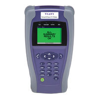
SmartClass E1/Datacom
JDS Uniphase SmartClass E1/Datacom Tester Manuals
Manuals and User Guides for JDS Uniphase SmartClass E1/Datacom Tester. We have
1
JDS Uniphase SmartClass E1/Datacom Tester manual available for free PDF download: User Manual
JDS Uniphase SmartClass E1/Datacom User Manual (144 pages)
Brand:
JDS Uniphase
| Category:
Test Equipment
| Size: 1 MB
Table of Contents
Table of Contents
7
About this Guide
13
Purpose and Scope
14
Assumptions
14
Safety and Compliance Information
14
Conventions
14
Chapter 1 Getting Started
17
Getting Started
17
Ship List
18
Features and Capabilities
18
Options
19
Configurations
19
Software Options
20
Optional Accessories
20
Preparation for Use
21
General Preparation
21
Charging the Batteries
22
Exploring the Front Panel
22
Status Leds
23
Lcd
24
Cancel Key
24
OK Key
24
Arrow Keys
24
Keypad
24
Action Key
24
Start Key
24
Backlight Key
24
Power Key
24
Exploring the Side Panels
25
Left Side Panel
25
Right Side Panel
25
Exploring the Bottom Panel
26
Powering on Your Unit
26
Powering off Your Unit
26
Navigating the User Interface
27
Menu Screens
28
Data Entry Screens
29
Result Screens
29
Using the Keypad
30
Selecting a Menu Option or a Configuration Setting
30
Returning to a Previous Menu
30
Entering Numeric Values
30
Typing Text
30
Chapter 2 Instrument Settings
33
Instrument Settings
33
Setting the Language
34
Viewing the Software and Hardware Information
34
Setting the Date and Time
35
Changing the Date or Time Format
35
Setting the Date or Time
35
Adjusting the Contrast and Brightness
36
Determining the Specified Battery Type
36
Managing Files
36
Specifying DB9 Port Usage
37
Basic Testing
39
Setting Options
37
Restoring Factory Defaults
37
Chapter 3 Basic Testing
39
Managing Test Configurations
40
Saving a Configuration
40
Restoring a Configuration
40
Viewing a Configuration
40
Starting or Restarting a Test
41
Stopping a Test
41
Timed Testing
41
Viewing Test Results
42
Remote Control
42
Chapter 4 E1 Testing
43
E1 Testing
43
About E1 Testing
44
Launching an E1 Test Application
44
Specifying Test Application Settings
45
Specifying a Test Mode
45
Configuring Test Settings Automatically
46
Specifying Interface Settings
46
Specifying E1 Framing Settings
47
Specifying E1 Signaling (Abcd/Sa) Settings
48
Specifying a BERT Pattern
49
Specifying Error/Alarm Settings
51
Specifying Performance Settings
52
Specifying VF Settings
53
Monitoring a Circuit
54
Measuring Timing Slips
55
Terminate Testing
56
Line Loopback Testing
57
Pulse Shape Analysis
58
Measuring Jitter
59
Configuring Test Settings
59
Connecting to the Circuit
61
Running the Test
61
Testing MFC-R2 Signaling
62
Configuring Test Settings
62
Connecting to the Line
65
Running the Test
65
Chapter 5 Datacom Testing
67
Datacom Testing
67
About Data Communications Testing
68
Launching the Datacom Application
68
Specifying Test Settings
69
Specifying the Test Mode
69
Specifying the Interface Standard
69
Specifying Timing Parameters
70
Specifying the Timing Mode
70
Specifying Transmit and Receive Timing
70
Specifying Polarity Settings
71
Specifying a BERT Pattern
71
Specifying Data Parameters
73
Specifying the Data Rate
73
Enabling/Disabling Data Loss Detection
74
Specifying the Rx Input
74
Specifying the Clock Loss Threshold
74
Specifying Async Settings
74
Specifying Flow Control Settings
75
Specifying G.821 Performance Settings
76
Specifying Error Settings
76
Performing a Self Test
77
Connecting the E1/Datacom Tester to the Circuit
77
Connecting for X.21 Testing
78
Connecting for RS-232/V.24 and EIA-530 Testing
78
Connecting for V.35 Testing
78
Connecting for RS-449/V.36 Testing
78
BER Testing
79
Monitoring a Datacom Interface
80
Frame Relay Testing
80
Launching the Frame Relay Application
80
Configuring the Test Mode
81
Specifying Datacom Settings
81
Configuring the Frame Load Settings
82
Configuring the Frame Header Settings
84
Configuring the LMI Settings
85
Configuring the Trace Settings
86
Specifying Flow Control Settings
86
Specifying Polarity Settings
87
Monitoring Traffic on Datacom Interfaces
87
Transmitting Traffic over a Datacom Interface
88
Chapter 6 VT100 Terminal Emulation
89
About VT100
90
VT100 Cabling
90
Emulating a VT100 Terminal
90
Chapter 7 Test Results
93
Test Results
93
E1 Results
94
E1 Summary Results
94
Statistics Results
95
Signal Results
95
Interface Results
96
Frame Data Results
97
Timeslot Results
97
BERT Results
97
Performance Results
98
G.821 Results
98
G.826 ISM Results
99
G.826 OOS Results
100
M.2100 ISM Results
100
M.2100 OOS Results
101
VF Results
102
Freezing Test Results
102
Pulse Shape Results
102
Summary
102
Pulse Shape
104
Jitter Results
104
Summary Results
104
Jitter Results
105
Graphical and Tabular Jitter Results
105
Jitter Graph
105
MTJ Graph and Table
105
JTF Graph
105
Signal Results
105
Interface Results
105
BERT Results
105
Event Log
105
Event Histogram
105
MFC-R2 Results
106
Datacom Results
106
Summary Results
106
Clock Results
107
Control Signal Results
107
Data Results
108
BERT Results
109
G.821 Performance Results
110
Event Log
110
Event Histogram
110
Frame Relay Results
110
Summary Results
110
Clock Results
112
Control Signal
112
Data Results
112
DLCI Results
112
Link Results
113
Ping Results
115
LMI Results
116
DLCI List Results
116
Trace Results
116
Event Log
116
Event Histogram
117
Saving Results
117
Viewing Saved Results
117
Chapter 8 Maintaining the Batteries
119
Prolonging Battery Life
120
Recharging the Batteries
120
Replacing the Batteries
121
Chapter 9 Troubleshooting
123
Troubleshooting
123
Getting Technical Assistance
124
Resolving Problems
124
General Testing
124
E1 Testing
125
Datacom Testing
126
Appendix A Signal Lead Names
127
Appendix B Specifications
129
E1 Interface Connector Specifications
130
Physical Interface Specifications
130
Transmitter
130
Receivers
130
This Appendix Contains Specifications for the E1 Tester. Topics Discussed in
130
This Appendix Include the Following:
130
E1 Circuit Testing Specifications
131
Pulse Shape Specifications
132
Jitter Specifications
132
Standards
133
Manual Jitter Measurement
133
MTJ and FMTJ Measurements
133
Jitter Transfer Measurement
133
Datacom Specifications
134
Supported Interface Standards
134
About Pin Assignments
134
RS-232/V.24 Pin Assignments
134
X.21 Pin Assignments
135
Pin Assignments
136
V.35 Pin Assignments
137
RS-449/V.36 Pin Assignments
138
Signal Lead Names
139
Physical Specifications
140
Environmental Specifications
140
Power Specifications
140
Warranty Information
141
Advertisement
Advertisement
Related Products
JDS Uniphase SmartClass E1
JDS Uniphase OTU-8000 (EOTU8000E)
JDS Uniphase SmartClass VDSL
JDS Uniphase SmartClass
JDS Uniphase 2100
JDS Uniphase 2303/01
JDS Uniphase 2303/02
JDS Uniphase 2303/03
JDS Uniphase 2303/04
JDS Uniphase 2303/11
JDS Uniphase Categories
Test Equipment
Measuring Instruments
Control Unit
Cable Tester
Switch
More JDS Uniphase Manuals
Login
Sign In
OR
Sign in with Facebook
Sign in with Google
Upload manual
Upload from disk
Upload from URL