Sign In
Upload
Manuals
Brands
Invertek Drives Manuals
Controller
ODL-2-22010-1HF42-SN
Invertek Drives ODL-2-22010-1HF42-SN Manuals
Manuals and User Guides for Invertek Drives ODL-2-22010-1HF42-SN. We have
1
Invertek Drives ODL-2-22010-1HF42-SN manual available for free PDF download: Installation & Operating Instructions Manual
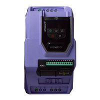
Invertek Drives ODL-2-22010-1HF42-SN Installation & Operating Instructions Manual (76 pages)
optidrive elevator series AC Variable Speed Drive for Control of Geared and Gearless Elevator Motors
Brand:
Invertek Drives
| Category:
Controller
| Size: 4 MB
Table of Contents
Table of Contents
3
1 Introduction
5
Important Safety Information
5
2 Electrical Installation Quick Reference
6
3 Optidrive P2 Elevator Features and Functions
7
4 Product Ratings
8
Drive Model Numbers - IP20
8
Drive Model Numbers - IP55
8
5 Mechanical Installation
9
General
9
Routine Maintenance
9
UL Compliant Installation
9
Mechanical Dimensions and Weights (IP20 Units)
9
Guidelines for Enclosure Mounting (IP20 Units)
10
Mounting the Drive - IP20 Units
10
Mechanical Dimensions - IP55 Units
11
Guidelines for Mounting (IP55 Units)
12
Removing the Terminal Cover
12
6 Electrical Installation
13
Installation in Accordance with Good EMC Practice
13
Grounding the Drive
14
Electrical Connections (Mains Side)
15
Electrical Connections (Brake Resistor)
16
Electrical Connections (Motor Side)
17
Motor Thermal Overload Protection
17
Control Terminal Wiring
18
Control Terminals Connection Diagram
18
Control Terminal Connections
18
Control Terminal Configuration
19
Motor Contactor Control
19
Motor Holding Brake Control
20
7 Safe Torque off
22
8 Optional Encoder Interface Modules
26
Encoder Interface Module Mechanical Installation
26
Encoder Interface Module Electrical Installation
26
Encoder Interface Module Parameter Setup
26
9 Managing the Keypad
27
Keypad Layout and Function - Standard LED Keypad
27
Changing Parameters
27
Advanced Keypad Operation Short Cuts
28
Drive Operating Displays
28
Resetting Parameters to Factory Default Settings
29
Resetting Parameters to User Default Settings
29
Elevator Specific Linear Units
29
10 Start up and Commissioning
30
Commissioning Flow Diagram
30
Motor Operating Modes
31
11 First Start-Up of Geared (Induction) Motors
32
Step 1- Wiring Connections
32
Step 2- Pre-Power Checks
33
Step 3- Apply Power
34
Step 4- Motor Nameplate Data Entry
34
Step 5- Motor Auto-Tune
34
Step 6 - Encoder Setup (if Encoder Is Installed)
35
Enhanced V/F Motor Control
36
12 Start-Up of Gearless (Permanent Magnet) Motor-With Encoder Feedback
37
Step 1- Wiring Connections
37
Step 2- Pre-Power Checks
38
Step 3- Apply Power
39
Step 4- Motor Nameplate Data Entry
39
Step 5- Motor Auto-Tune
40
Step 6- Encoder Setup
40
Step 7A- Stationary Encoder Offset Measurement (Alternative to Rotating Measurement)
41
Step 7B - Rotating Encoder Offset Measurement (Alternative to Stationary Measurement)
42
13 Comfort Optimisation
43
Ramp and Travel Jerk Adjustment Diagram
43
Speed Loop Gains
43
Comfort Optimisation Procedure
45
The below Guidance Assumes that Steps 1 Thru to 6 in Section 11(Geared)/12 (Gearless) Have Already Been Performed
45
14 Advanced Features
47
Short Floor Operation
47
Rescue Mode Operation (UPS Power Supply)
48
Motor Presence Check before Opening Mechanical Brake
49
Motor Brake Release Monitoring
50
15 Gearless (Permanent Magnet) Motors-Without Encoder (P4-01=3)
51
Step 1- Wiring Connections
51
Step 2- Pre-Power Checks
51
Step 3- Apply Power
51
Step 4- Motor Nameplate Data Entry
51
Step 5- Motor Auto-Tune
52
16 Parameters
53
Parameter Set Overview
53
Parameter Group 1 - Speed Limits, Basic Motor Data, Command Source
53
Parameter Group 2 - Travel Speeds, I/O Setup
54
Parameter Group 3 - S-Ramps, Output Contactor/Brake, Short Floor, Light Load Detection
57
Parameter Group 4 -Motor Control Modes, Speed Loop Gains, Current Limits
58
Parameter Group 5 - Modbus, CAN Open Communication
59
Parameter Group 6: Encoder Setup, Brake Release Monitoring
60
Parameter Group 7: Motor Measured Data, Rollback Control Gains
61
Group 8 and Group 9: Refer to Optitools Studio Commissioning Tool
62
Parameter Group 0 - Monitoring Parameters (Read Only)
62
17 Serial Communications
64
RS-485 Communications
64
Modbus RTU Communications
64
18 Technical Data
66
Environmental
66
Input Voltage Ranges
66
Output Power and Current Ratings
67
Additional Information for UL Approved Installations
68
Derating Information
69
19 Troubleshooting
70
Fault Messages
70
Notes
72
Notes
73
20 User Settings Table
74
21 Quick Reference Sheet
76
Terminal Functions (Default Settings)
76
Speed Profile Setup
76
Advertisement
Advertisement
Related Products
Invertek Drives ODL-2-22075-1KF42-SN
Invertek Drives ODL-2-22150-1KF42-SN
Invertek Drives ODL-2-22020-1HF42-SN
Invertek Drives ODL-2-22220-1KF42-SN
Invertek Drives ODL-2-22030-1HF42-SN
Invertek Drives ODL-2-24400-3KF42-SN
Invertek Drives ODL-2-24050-3HF42-SN
Invertek Drives ODL-2-62040-3HF4N-S
Invertek Drives ODL-2-62030-3HF4N-SN
Invertek Drives ODL-2-44300-3HF4N-SN
Invertek Drives Categories
DC Drives
Inverter
Controller
Media Converter
Keypad
More Invertek Drives Manuals
Login
Sign In
OR
Sign in with Facebook
Sign in with Google
Upload manual
Upload from disk
Upload from URL