Sign In
Upload
Manuals
Brands
Infors HT Manuals
Laboratory Equipment
Minifors 2
Infors HT Minifors 2 Manuals
Manuals and User Guides for Infors HT Minifors 2. We have
2
Infors HT Minifors 2 manuals available for free PDF download: Operating Manual
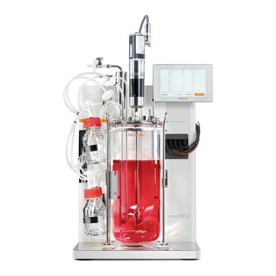
Infors HT Minifors 2 Operating Manual (234 pages)
Bench-Top Bioreactor
Brand:
Infors HT
| Category:
Laboratory Equipment
| Size: 23 MB
Table of Contents
Supplemental Directives
3
Table of Contents
4
Safety and Responsibility
13
Other Messages
13
Intended Use, Incorrect Use and Misuse
14
Unauthorised Persons
15
Responsibility of the Provider
16
Residual Risks
16
Warning Symbols on the Device
18
Declaration of Decontamination
19
Setup and Function
20
Basic Unit
20
Overview
20
Operating Panel
21
Power Switch
21
LED Strip - Status Indicator
21
Mains Connection
22
Water Connections
22
Gas Connections
23
Signal Connections
23
Motor Cable Connection
25
Connections for Sensors (Sensor Cables)
25
Gassing Connection
26
Connections Exit Gas Cooler and Valve for Water
26
Flow
26
Pumps
27
Identification Plate
28
Culture Vessel
29
Overview
29
Top Plate
30
Ports in the Vessel Top Plate
31
Temperature Control System
34
Stirrer
35
Overview
35
Motor
35
Impeller
37
Gassing System
38
Ph Control
39
Control
41
Antifoam Control
43
Options
44
Turbidity Measurement
44
Setup and Function
44
Mounting the Turbidity Sensor
46
Exit Gas Analysis
47
Setup and Function
47
Connecting the Gas Sensor
47
Redox Measurement
49
Balances
50
Accessories
51
Accessories in the Scope of Delivery
51
Cone Plug for Drive Hub
52
Sparger
52
Baffles
53
Blanking Plugs
53
Clamping Adapters and Fastening Screws
54
Sensor Holder
55
Addition Port Adapters and Feed Needles
55
Septum Collar
57
Dip Tubes
57
Immersion Pocket for Temperature Sensor (Pt100)
58
Exit Gas Cooler
59
Cold Finger
61
Reagent Bottles
62
Sampling System Super Safe Sampler
63
Pump Heads
65
Vessel Holder
66
Sterile Filters
67
Hoses and Accessories
69
O-Rings and Gaskets
70
Inoculation Accessories and Tools
70
Starter Set
71
Service Sets
71
Auxiliary Supplies
71
Transport and Storage
72
Transport
72
Storage
72
Installation and Commissioning
73
Operating Conditions at the Installation Location
73
Minimum Distances to the Device
73
Connecting the Device to On-Site Supply Lines
73
Power Supply
74
Water Supply and Return
74
Gas Supply
75
Exit Gas
76
Connecting the Motor Cable
76
Test Run
77
Before Cultivation
82
Preparing the Culture Vessel
82
Checking Gaskets (O-Rings)
82
Mounting the Impellers
83
Mounting Dip Tubes and Spargers
84
Inserting the Vessel into the Vessel Holder
85
Inserting the Baffles
86
Moistening/Filling the Culture Vessel
86
Mounting the Top Plate
87
Mounting the Blanking Plugs
88
Mounting Addition Port Adapters
89
Mounting the Feed Needles
89
Mounting the Immersion Pocket for Temperature
90
Sensor (Pt100)
90
Equipping a Port with Septum Collar and Septum for Inoculation
90
Preparing the Dip Tube / Addition Port Adapter for Inoculation
92
Mounting the Exit Gas Cooler
92
Mounting the Cold Finger
93
Preparing the Sensors
94
Calibrating the Ph Sensor
95
Mounting Sensors into 12 MM Ports
95
Mounting Sensors with Sensor Holder
96
Mounting the Antifoam Sensor
98
Preparing the Sampling System Super Safe Sampler
99
Mounting the Sparger Hose and the Inlet Air Filter
100
Space Gassing
101
Preparing the Reagent Bottles, Pumps and Hoses
102
Sterile Hose Connections
105
Setting the Pumps
105
Removing the Pump Heads
105
Fitting the Cone Plug for Drive Hub
106
Autoclaving the Culture Vessel
107
Checklist before Autoclaving
107
Autoclaving
108
Connecting the Culture Vessel and Preparing the Cultivation
110
Pump Heads
110
Filling the Reagent Hoses
110
Connecting the Gassing
111
Connecting the Exit Gas Cooler
112
Connecting the Cold Finger
112
Coupling the Motor
112
Filling the Culture Vessel
113
Connecting the Temperature Sensor (Pt100)
114
Connecting the Antifoam Sensor
114
Connecting the Ph Sensor
115
Connecting the Po
115
Sensor
115
Calibrating the Po
116
Sensor
116
Checking the Hoses and Hose Connections
116
Cultivation
117
Preparing the Medium
117
Sampling
117
Inoculation
121
Inoculation with a Syringe
121
Inoculation Using Dip Tube / Addition Port Adapter
122
Harvest
122
Emptying the Culture Vessel
123
Emptying the Reagent Hoses
124
Autoclaving the Culture Vessel after Cultivation
125
Operation
127
Screen Areas, Menu Navigation and Control Elements
127
Overview
127
Main Screen
128
Edit View
130
Start Batch / Inoculate / Stop Batch
131
Sample Now
132
Menus for System Settings
134
Overview
134
VESSEL TYPE - Selecting a Culture Vessel
135
APPEARANCE - Display Settings
136
Network Settings
138
EVE COMMUNICATION - Communication Settings
139
USB Data Export and Import from a USB Stick
140
SYSTEM INFO - System Information
143
Parameter - Parameter Groups
144
Overview
144
Parameters - Displays and Functions
145
SETPOINT - Setting the Setpoint
146
Parameter Alarms
147
Cascades
149
MAIN Parameter Group
150
Temperature
150
Stirrer
151
Total Flow
155
Gasmix
155
Foam
156
EXTENDED Parameter Group
158
Balance (Optional)
158
Flow Parameters
159
Turbidity (Optional)
161
Redox (Optional)
161
Analog IO1 & Analog IO2
161
EXIT GAS Parameter Group
163
Exit Gas O
163
Exit Gas CO
163
PUMPS Parameter Group
164
Overview
164
Configuring the Pumps
165
Pump1
167
Pump2
167
Pump3
167
Pump4
168
AUTO FILL/EMPTY - Automatically Filling/Emptying Pump Hoses
169
Calibrating the Sensors
171
Calibrating the Ph Sensor
171
Ph Sensor Product Calibration
175
Calibrating the Po
177
Sensor
177
Calibrating the Turbidity Sensor
180
PID Controller - Basic Principle
182
Tips for Readjusting a PID Controller
183
Adjusting PID Settings
183
Alarms - Equipment Alarm Menu
184
Switching off the Device
185
10 Cleaning and Maintenance
186
Cleaning Agent and Disinfectant
186
Cleaning the Culture Vessel - Routine Cleaning
187
Removing the Vessel Top Plate and Accessories
188
Removing the Exit Gas Cooler
188
Removing the Sensors
190
Removing Hoses, Filters and Pump Heads
190
Removing Blanking Plugs
191
Removing the Septum Collar and Septum
191
Removing Addition Port Adapters, Feed Needle and Temperature Sensor Immersion Pocket
192
Removing the Vessel Top Plate
192
Removing the Sparger and the Dip Tube(S)
193
Removing the Impellers
193
Cleaning and Storing Individual Parts
194
Cleaning the Sensors
195
Cleaning the Hoses and Pump Heads
195
Cleaning the Super Safe Sampler
195
Cleaning the Basic Unit and Operating Panel
196
Maintenance Plan
196
10.10 Decalcifying the Device
197
11 Rectifying Faults
199
General Faults
199
Faults Drive System
200
Faults Temperature Control System
201
Faults Gassing System
202
Faults Ph Control
204
Faults Po
206
Control
206
Faults Antifoam/Level and Pump
207
Faults Feed and Pump
208
Interferences Turbidity Measurement
209
Replacing Device Fuses
210
Behaviour in Case of a Power Interruption
210
Returning for Repair
210
12 Disassembly and Disposal
211
Disassembly
211
Disposal
211
13 Technical Data
213
Dimensions
213
Weight
217
Connections and Connection Values
217
Electrical Connection and Power Values
217
Water
218
Process Gas
219
Specifications of the Basic Unit
219
Operating Panel
219
Culture Vessel
219
Stirrer
221
Temperature Control System
224
Gassing System
225
Ph Control
227
Control
228
Antifoam Control
228
Pumps
229
Specifications of the Options
229
Turbidity Measurement
229
Exit Gas Analysis
230
Redox Measurement
230
Operating Conditions
231
Emissions
231
14 EU Declaration of Conformity
232
EG-Konformitätserklärung
233
Advertisement
Infors HT Minifors 2 Operating Manual (217 pages)
Benchtop Bioreactor
Brand:
Infors HT
| Category:
Laboratory Equipment
| Size: 8 MB
Table of Contents
Table of Contents
3
1 General Information
11
About this Manual
11
Explanation of Special Notices
11
Warning Notices
11
Other Notices
12
Equipment Identification (Standard Identification Plate)
12
Declaration of Conformity
13
Customer Service and Services
13
2 Safety and Responsibility
14
Intended Use, Incorrect Use and Misuse
14
Qualified Personnel
15
Provider
15
User
15
Operator
16
Unauthorised Persons
17
Responsibility of the Provider
17
General Hazards
17
Electrical Current
18
Unauthorised Spare Parts and Accessories
18
Particular Hazards
18
Hot Surfaces
19
Dangerous Gases
19
Flammable or Explosive Substances
19
Corrosive or Toxic Substances
19
Bioactive Substances or Pathogenic Organisms
20
Overpressure or Vacuum
20
Warning Symbols on the Equipment
20
Declaration of Decontamination
21
3 Setup and Function
22
Basic Unit
22
Main Switch
23
LED Strip
23
Pumps
23
Identification Plate
24
Power Connection
25
Water Connections
25
Gas Connections
25
Signal Connections
26
Motor Cable Connection
26
Connections for Sensors (Sensor Cables)
27
Sparger Connection (Gassing)
27
Connections and Water Flow Control Valve for the Exit Gas Cooler
28
Operating Panel
29
Culture Vessel
29
Top Plate
31
Ports in the Vessel Top Plate and Their Configuration
32
Vessel Top Plate, Nominal Width 90
32
Vessel Top Plate, Nominal Width 115
33
Vessel Top Plate, Nominal Width 145
34
Temperature Control System
35
Stirrer
36
Gassing System
37
Gas Entry
38
Exit Gas
38
Ph Control
38
Measurement System
38
Po Control
39
Measurement System
40
Antifoam Control
41
Antifoam Sensor
41
4 Options
42
Turbidity Measurement
42
Sensors
43
Calibrating the Zero Point
43
Mounting the Sensor
44
Cleaning and Storing the Sensor
44
Interferences Turbidity Measurement
45
Specifications
45
Exit Gas Analysis
46
Gas Sensors
46
Connecting the Gas Sensor
46
Calibrating the Gas Sensor
47
5 Accessories
48
Cone Plug for Drive Hub
48
Sparger
49
Baffles
49
Blanking Plugs
50
Clamping Adapters and Fastening Screws
50
Electrode Holder
51
Addition Port Adapters and Feed Needles
52
Septum Collar
53
Dip Tubes
53
Pocket for Temperature Sensor (Pt100)
54
Exit Gas Cooler
55
Reagent Bottles
56
Sampling System Super Safe Sampler
56
Pump Heads
59
Vessel Holder with Built-In Holder for Reagent Bottles and Pumps
60
Sterile Filters
60
Hoses and Accessories
62
O-Rings and Gaskets
63
Inoculation Accessories and Tools
63
Starter Kit
64
Service Sets
64
Auxiliary Supplies
64
6 Transport and Storage
65
Transport
65
Storage
66
7 Installation and Initial Operation
67
General Location Requirements for Installation
67
Minimum Distances
67
Connecting the Equipment to On-Site Supply Lines
67
Power Supply
68
Water Supply and Return
68
Gas Supply
69
Exit Gas
70
Connecting the Motor Cable
70
Test Run
71
Preparation Test Run
71
Cooling System
72
Stirring
73
Heating and Adjusting Temperature
73
Gassing
74
End of Test
74
8 Before Cultivation
76
Preparing and Autoclaving the Culture Vessel
76
Checking Gaskets (O-Rings)
76
Mounting the Impellers
77
Mounting Dip Tubes and Spargers
78
Inserting the Vessel into the Vessel Holder
79
Inserting the Baffles
80
Moistening/Filling the Culture Vessel
81
Fitting the Vessel Top Plate
81
Mounting the Blanking Plugs
82
Mounting Addition Port Adapters
83
Mounting the Feed Needle(S)
84
Mounting the Pocket for Temperature Sensor (Pt100)
84
Equipping the Port with a Septum Collar and Septum for Inoculation
84
Preparing the Dip Tube/Addition Port Adapter for Inoculation
85
Mounting the Exit Gas Cooler
86
Preparing the Sensors
87
Calibrating the Ph Sensor
88
Mounting a Sensor into a 12 MM Port
88
Mounting Sensors with Electrode Holder
89
Mounting the Antifoam Sensor
91
Preparing the Super Safe Sampler
93
Mounting the Sparger Hose and the Inlet Air Filter
94
Preparing the Reagent Bottles, Pumps and Hoses
95
Sterile Hose Connections
98
Setting the Pumps
99
Removing the Pump Heads
99
Fitting the Cone Plug for Drive Hub
100
Checklist before Autoclaving
100
Autoclaving
101
Connecting the Culture Vessel and Preparing the Cultivation
103
Hang the Culture Vessel in Place and Fit the Pump Heads
103
Filling the Reagent Hoses
103
Connecting the Gassing
104
Connecting the Exit Gas Cooler
104
Coupling the Motor
105
Filling the Culture Vessel
106
Connecting the Temperature Sensor (Pt100)
107
Connecting the Antifoam Sensor
107
Connecting the Ph Sensor
108
Connecting the Po
108
Sensor
108
Calibrating the Po Sensor
109
Checking the Hoses and Hose Connections
109
9 Cultivation
110
Preparing the Medium
110
Sampling
111
Inoculation
114
Inoculation with a Syringe
115
Inoculation Using Dip Tube / Addition Port Adapter
115
Harvest
116
Emptying the Culture Vessel
117
Emptying the Reagent Hoses
117
Switching off the Equipment
117
Autoclaving the Culture Vessel after Cultivation
118
10 Operation
120
Screen Areas, Menu Navigation and Control Elements
120
Main Screen
122
Edit View
123
Start Batch / Inoculate / Stop Batch
124
Sample Now
125
Menus for System Settings
126
VESSEL TYPE - Selecting a Culture Vessel
127
APPEARANCE - Display Settings
128
Network Settings
130
Eve COMMUNICATION - Communication Settings
132
USB Data Export and Import from a USB Stick
133
SYSTEM INFO - System Information
136
Parameter - Parameter Groups
136
Parameters - Displays and Functions
137
SETPOINT - Setting the Setpoint
139
Parameter Alarms
140
Cascades
142
MAIN Parameter Group
143
Temperature
143
Stirrer
143
Po 2
145
Totalflow
148
Gasmix
148
Foam
149
EXTENDED Parameter Group
151
Turbidity (Optional)
151
Balance (Optional)
151
Airflow
151
Gas2Flow
152
EXITGAS Parameter Group
153
Exit Gas O
153
Exit Gas CO
154
PUMPS Parameter Group - General Information
154
Configuring the Pumps
156
Pump1 - Acid or Additional Feed Solution
157
Pump2 - Base or Additional Feed Solution
158
Pump3 - Antifoam, Level or Additional Feed Solution
158
Pump4 - Feed Solution
159
AUTO FILL/EMPTY - Automatically Filling/Emptying Pump Hoses
160
Calibration
161
Calibrating the Ph Sensor - General Information
161
Calibrating the Ph Sensor - Procedure
162
Ph Sensor Product Calibration
167
Calibrating the Po Information
170
Calibrating the Po Sensor - Procedure
171
Calibrating the Turbidity Sensor - General Information
178
Calibrating the Turbidity Sensor - Procedure
178
PID Controller - Basic Principle
180
Useful Information for Changing PID Controller Settings
182
Adjusting PID Settings
183
Alarms - Equipment Alarm Menu
183
11 Cleaning and Maintenance
185
Cleaning Agent and Disinfectant
185
Cleaning the Culture Vessel - Routine Cleaning
185
Removing the Vessel Top Plate and Accessories
187
Cleaning and Storing Individual Parts
191
Removing the Impellers
191
Cleaning the Sensors
192
Cleaning the Hoses and Pump Heads
192
Cleaning the Super Safe Sampler
193
Cleaning the Exit Gas Cooler
193
Cleaning the Basic Unit and Operating Panel
194
Maintenance Plan
194
Decalcifying the Equipment
195
12 Interferences
197
Interferences Basic Unit and Operating Panel
197
Interferences Drive System
198
Interferences Temperature Control System
199
Interferences Gassing System
199
Interferences Ph-System
200
Interferences Po
202
System
202
Interferences Antifoam/Level Sensor and Antifoam
203
Pumps
203
Interferences Addition of Feed Solution (Feed Pump)
204
Returning for Repair
204
13 Disassembly and Disposal
205
Disassembly
205
Disposal
205
14 Technical Data
207
Equipment Dimensions
207
Dimensions of Culture Vessel
208
Weights (Netto)
209
Connection Requirements
209
Electrical
209
Water IN, Basic Unit
209
Water OUT, Basic Unit
209
Gas (Air, O 2 or N 2 )
210
Specifications
210
Operating Panel
210
Culture Vessels
210
Stirrer
211
Temperature
212
Gassing
213
Antifoam
214
Pumps
215
Operating Conditions
215
Emissions
215
Auxiliary Supplies
216
Advertisement
Related Products
Infors HT Ecotron
Infors HT Labfors 5
Infors HT Labfors 5 Cell
Infors HT Minitron
Infors HT Multifors 2
Infors HT Multitron
Infors HT Multitron Pro
Infors HT Multitron Standard
Infors HT Techfors-S
Infors HT Categories
Laboratory Equipment
Paint Sprayer
Farm Equipment
More Infors HT Manuals
Login
Sign In
OR
Sign in with Facebook
Sign in with Google
Upload manual
Upload from disk
Upload from URL