Sign In
Upload
Manuals
Brands
IEI Technology Manuals
Single board computers
KINO-DAL-N1
IEI Technology KINO-DAL-N1 Manuals
Manuals and User Guides for IEI Technology KINO-DAL-N1. We have
1
IEI Technology KINO-DAL-N1 manual available for free PDF download: User Manual
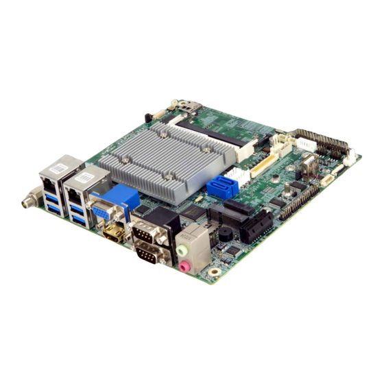
IEI Technology KINO-DAL-N1 User Manual (151 pages)
KINO-DAL series Mini-ITX SBC Intel 14nm Atom, Pentium or Celeron on-board SoC supports dual-channel DDR3L SO-DIMMs; COM, USB 3.0, SATA 6Gb/s, M.2, eMMC 5.0 and audio support
Brand:
IEI Technology
| Category:
Single board computers
| Size: 4.09 MB
Table of Contents
Table of Contents
5
1 Introduction
15
Introduction
16
Figure 1-1: KINO-DAL
16
Model Variations
17
Features
17
Table 1-1: KINO-DAL Model Variations
17
Connectors
18
Figure 1-2: Connectors (Front Side)
18
Dimensions
19
Figure 1-3: Dimensions (MM)
19
Data Flow
20
Figure 1-4: Data Flow Diagram
20
Technical Specifications
21
Table 1-2: Technical Specifications
23
2 Unpacking
24
Anti-Static Precautions
25
Unpacking Precautions
25
Packing List
26
Optional Items
27
3 Connectors
28
Peripheral Interface Connectors
29
KINO-DAL Layout
29
Figure 3-1: Connector and Jumper Locations
29
Peripheral Interface Connectors
30
External Interface Panel Connectors
31
Table 3-1: Peripheral Interface Connectors
31
Table 3-2: Rear Panel Connectors
31
Internal Peripheral Connectors
32
Audio Connector
32
Figure 3-2: Audio Connector Location
32
Table 3-3: Audio Connector Pinouts
32
Battery Connector
33
Figure 3-3: Battery Connector Location
33
Chassis Intrusion Connector
34
Figure 3-4: Chassis Intrusion Connector Location
34
Table 3-4: Battery Connector Pinouts
34
Table 3-5: Chassis Intrusion Connector Pinouts
34
DC-IN Power Connector
35
Figure 3-5: DC-IN Power Connector Location
35
Table 3-6: DC-IN Power Connector Pinouts
35
Digital I/O Connector
36
Figure 3-6: Digital I/O Connector Location
36
Table 3-7: Digital I/O Connector Pinouts
36
Fan Connector, CPU
37
Figure 3-7: CPU Fan Connector Locations
37
Table 3-8: CPU Fan Connector Pinouts
37
Fan Connector, System
38
Figure 3-8: System Fan Connector Locations
38
Table 3-9: System Fan Connector Pinouts
38
Front Panel Connector
39
Figure 3-9: Front Panel Connector Location
39
Table 3-10: Front Panel Connector Pinouts
39
I 2 C Connector
40
Figure 3-10: I2C Connector Pinout Locations
40
Table 3-11: I2C Connector Pinouts
40
Keyboard and Mouse Connector
41
Figure 3-11: Keyboard and Mouse Connector Location
41
Table 3-12: Keyboard and Mouse Connector Pinouts
41
LAN LED Connectors
42
Figure 3-12: LAN LED Connector Locations
42
Table 3-13: LAN LED Connector Pinouts
42
LCD Inverter Connector
43
Figure 3-13: LCD Inverter Connector Location
43
Table 3-14: LCD Inverter Connector Pinouts
43
LVDS Connector
44
Figure 3-14: LVDS Connector Location
44
Slot
45
Figure 3-15: M.2 Slot Location
45
Table 3-15: LVDS Connector Pinouts
45
Microsd Slot (Optional)
46
Pcie Mini Card Slot
46
Figure 3-16: Microsd Card Slot Location
46
Figure 3-17: Pcie Mini Card Slot Location
47
Pcie X1 Card Slot
48
Figure 3-18: Pcie X1 Slot Location
48
Table 3-16: Pcie Mini Card Slot Pinouts
48
Serial Port Connector
49
Table 3-17: Pcie X1 Slot Pinouts
49
Figure 3-19: RS-232 Serial Port Connector Locations
50
Table 3-18: RS-232 Serial Port Connector Pinouts
50
SATA 6Gb/S Drive Connectors
51
Figure 3-20: SATA 6Gb/S Drive Connectors Locations
51
SATA Power Connectors
52
Figure 3-21: SATA Power Connector Locations
52
Table 3-19: SATA Power Connector Pinouts
52
SIM Card Slot (Optional)
53
Figure 3-22: SIM Card Slot Location
53
Smbus Connector
54
Figure 3-23: Smbus Connector Location
54
Table 3-20: Smbus Connector Pinouts
54
SPI Flash Connector, BIOS
55
Figure 3-24: BIOS SPI Flash Connector Location
55
Table 3-21: BIOS SPI Flash Connector Pinouts
55
SPI Flash Connector, EC
56
Figure 3-25: EC SPI Flash Connector Location
56
Table 3-22: EC SPI Flash Connector Pinouts
56
TPM Connector
57
Figure 3-26: TPM Connector Location
57
Table 3-23: TPM Connector Pinouts
57
USB Connectors
58
External Peripheral Interface Connector Panel
58
Figure 3-27: USB Connector Locations
58
Table 3-24: USB Connector Pinouts
58
Figure 3-28: External Peripheral Interface Connector
59
Audio Jacks
60
Figure 3-29: Audio Connector
60
Figure 3-30: HDMI Connector
61
HDMI Connector
61
Table 3-25: HDMI Connector Pinouts
61
Figure 3-31: LAN Connector
62
LAN & USB 3.0 Combo Connectors
62
Table 3-26: LAN Pinouts
62
Table 3-27: Connector Leds
62
Figure 3-32: USB 3.0 Port Pinout Locations
63
Table 3-28: USB 3.0 Port Pinouts
63
Figure 3-33: Power Jack
64
Power Connector
64
Figure 3-34: Serial Port Pinouts
65
RS-232/422/485 Serial Port Connectors (COM1, COM2)
65
Table 3-29: RS-232/422/485 Serial Port Pinouts
65
Figure 3-35: VGA Connector
66
Table 3-30: VGA Connector Pinouts
66
VGA Connector
66
4 Installation
67
Anti-Static Precautions
68
Installation Considerations
68
So-DIMM Installation
70
Figure 4-1: SO-DIMM Installation
70
Module Installation
71
Figure 4-2: Removing the M.2 Module Retention Screw and Plastic Ring
71
M.2 M Odule I Nstallation
71
Figure 4-3: Inserting the M.2 Module into the Slot at an Angle
72
Figure 4-4: Securing the M.2 Module
72
Pcie Mini Card Installation
73
Full-Size Pcie Mini Card Installation
73
Figure 4-5: Removing the Retention Screw
73
Figure 4-6: Inserting the Full-Size Pcie Mini Card into the Slot at an Angle
74
Figure 4-7: Securing the Full-Size Pcie Mini Card
74
Half-Size Pcie Mini Card Installation
75
Figure 4-8: Removing Retention Screw and Standoff
75
Figure 4-9: Installing the Standoff
76
Figure 4-10: Inserting the Half-Size Pcie Mini Card into the Slot at an Angle
76
SIM Card Installation (Optional)
77
Figure 4-11: Securing the Half-Size Pcie Mini Card
77
Figure 4-12: Unlock SIM Card Slot Cover
77
Figure 4-13: SIM Card Installation
78
Figure 4-14: Lock SIM Card Slot Cover
78
System Configuration
79
AT/ATX Mode Select Switch
79
Figure 4-15: AT/ATX Mode Select Switch Location
79
Table 4-1: AT/ATX Mode Select Switch Settings
79
Clear CMOS Button
80
Figure 4-16: Clear CMOS Button Location
80
Flash Descriptor Security Override Jumper
81
Figure 4-17: Flash Descriptor Security Override Jumper Location
81
Table 4-2: Flash Descriptor Security Override Jumper Settings
81
LVDS Voltage Select Jumper
82
Figure 4-18: LVDS Voltage Select Jumper Location
82
Table 4-3: LVDS Voltage Select Jumper Settings
82
LVDS Panel Resolution Select Switch
83
Figure 4-19: LVDS Panel Resolution Select Switch Location
83
Table 4-4: LVDS Panel Resolution Selection
83
And SATA2 Select Switch
84
Figure 4-20: M.2 and SATA2 Select Switch Location
84
Table 4-5: M.2 and SATA2 Select Switch Settings
84
Chassis Installation
85
Airflow
85
Motherboard Installation
85
Sata Drive Connection
85
Figure 4-21: SATA Drive Cable Connection
86
5 Bios
87
Introduction
88
Starting Setup
88
Using Setup
88
Getting Help
89
Unable to Reboot after Configuration Changes
89
BIOS Menu Bar
89
Table 5-1: BIOS Navigation Keys
89
Main
90
BIOS Menu 1: Main
90
Advanced
91
BIOS Menu 2: Advanced
91
ACPI Settings
92
BIOS Menu 3: ACPI Settings
92
F81866 Super IO Configuration
93
Serial Port N Configuration
93
BIOS Menu 4: F81866 Super IO Configuration
93
BIOS Menu 5: Serial Port N Configuration
93
Serial Port 1 Configuration
94
Serial Port 2 Configuration
95
Serial Port 3 Configuration
96
Serial Port 4 Configuration
97
Serial Port 5 Configuration
98
Serial Port 6 Configuration
99
Iwdd H/W Monitor
100
BIOS Menu 6: Iwdd H/W Monitor
100
Smart Fan Mode Configuration
101
BIOS Menu 7: Smart Fan Mode Configuration
101
USB Configuration
102
BIOS Menu 8: USB Configuration
102
CPU Configuration
103
BIOS Menu 9: CPU Configuration
103
RTC Wake Settings
105
BIOS Menu 10: RTC Wake Settings
105
Power Saving Configuration
106
BIOS Menu 11: Power Saving Configuration
106
Serial Port Console Redirection
107
BIOS Menu 12: Serial Port Console Redirection
107
Legacy Console Redirection Settings
108
BIOS Menu 13: Legacy Console Redirection Settings
108
IEI Feature
109
BIOS Menu 14: IEI Feature
109
Chipset
110
BIOS Menu 15: Chipset
110
North Bridge Configuration
111
BIOS Menu 16: North Bridge Configuration
111
Intel IGD Configuration
112
BIOS Menu 17: Intel IGD Configuration
112
LCD Control
114
BIOS Menu 18: LCD Control
114
South Bridge Configuration
116
BIOS Menu 19: South Bridge Configuration
116
HD-Audio Configuration
118
BIOS Menu 20: HD-Audio Configuration
118
PCI Express Configuration
119
BIOS Menu 21: PCI Express Configuration
119
Onboard LAN
120
BIOS Menu 22: Onboard LAN
120
Mpcie1
121
BIOS Menu 23: MPCIE1
121
SATA Configuration
122
BIOS Menu 24: SATA Configuration
122
Security
124
BIOS Menu 25: Security
124
Boot
125
BIOS Menu 26: Boot
125
Save & Exit
127
BIOS Menu 27: Save & Exit
127
6 Software Drivers
129
Software Installation
130
Figure 6-1: IEI Resource Download Center
130
A Regulatory Compliance
132
B Product Disposal
134
CBIOS Menu Options
136
D Terminology
139
E Digital I/O Interface
143
F Watchdog Timer
146
G Hazardous Materials Disclosure
149
Advertisement
Advertisement
Related Products
IEI Technology KINO-DAL-N2
IEI Technology KINO-DAL-E3W2
IEI Technology KINO-DAL-E2W2
IEI Technology KINO-DAL-E1W2
IEI Technology KINO-DBT-J1900-R10
IEI Technology KINO-DBT-N29301-R10
IEI Technology KINO-DBT-N28071-R10
IEI Technology KINO-DBT-E38XX1-R10
IEI Technology KINO-DAL
IEI Technology KINO-DQM871-i1
IEI Technology Categories
Motherboard
Touch Panel
Computer Hardware
Single board computers
Desktop
More IEI Technology Manuals
Login
Sign In
OR
Sign in with Facebook
Sign in with Google
Upload manual
Upload from disk
Upload from URL