Sign In
Upload
Manuals
Brands
IEI Technology Manuals
Single board computers
gKINO-R1606G
IEI Technology gKINO-R1606G Manuals
Manuals and User Guides for IEI Technology gKINO-R1606G. We have
1
IEI Technology gKINO-R1606G manual available for free PDF download: User Manual
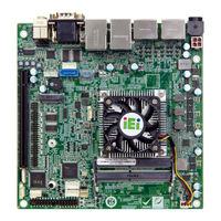
IEI Technology gKINO-R1606G User Manual (125 pages)
Mini-ITX SBC
Brand:
IEI Technology
| Category:
Single board computers
| Size: 3.21 MB
Table of Contents
Table of Contents
5
Introduction
15
Introduction
16
Figure 1-1: Gkino-V/R1000
16
Model Variations
17
Features
17
Table 1-1: Model Variations
17
Connectors
18
Figure 1-2: Connectors
18
Dimensions
19
Figure 1-3: Gkino-V1000 Dimensions (MM)
19
Figure 1-4: Gkino-R1000 Dimensions (MM)
20
Data Flow
21
Figure 1-5: Data Flow Diagram
21
Technical Specifications
22
Table 1-2: Technical Specifications
24
Unpacking
25
Anti-Static Precautions
26
Unpacking Precautions
26
Packing List
27
Optional Items
28
Connectors
29
Peripheral Interface Connectors
30
Gkino-V/R1000 Layout
30
Figure 3-1: Connector and Jumper Locations
30
Peripheral Interface Connectors
31
External Interface Panel Connectors
32
Table 3-1: Peripheral Interface Connectors
32
Table 3-2: Rear Panel Connectors
32
Internal Peripheral Connectors
33
DC-IN Power Connector
33
Figure 3-2: DC-IN Power Connector Location
33
Table 3-3: DC-IN Power Connector Pinouts
33
Audio Connector
34
Figure 3-3: Audio Connector Location
34
Table 3-4: Audio Connector Pinouts
34
Audio Amplifier Connectors
35
Figure 3-4: Audio Amplifier Connector Locations
35
Table 3-5: Audio Amplifier Connector Pinouts (SPK_L1)
35
Table 3-6: Audio Amplifier Connector Pinouts (SPK_R1)
35
Battery Connector
36
Figure 3-5: Battery Connector Location
36
Cctalk Connectors
37
Figure 3-6: Cctalk Connector Locations
37
Table 3-7: Battery Connector Pinouts
37
Table 3-8: Cctalk Connector Pinouts
37
Chassis Intrusion Connector
38
Figure 3-7: Chassis Intrusion Connector Location
38
Table 3-9: Chassis Intrusion Connector Pinouts
38
Digital I/O Connector
39
Figure 3-8: Digital I/O Connector Location
39
Table 3-10: Digital I/O Connector Pinouts
39
EC Debug Connector
40
Figure 3-9: EC Debug Connector Location
40
Table 3-11: EC Debug Connector Pinouts
40
Fan Connectors
41
Figure 3-10: Fan Connector Locations
41
Table 3-12: Fan Connector Pinouts
41
Front Panel Connector
42
Figure 3-11: Front Panel Connector Location
42
Table 3-13: Front Panel Connector Pinouts
42
I 2 C Connector
43
Figure 3-12: I 2 C Connector Location
43
Table 3-14: I 2 C Connector Pinouts
43
LAN LED Connectors
44
Figure 3-13: LAN LED Connector Locations
44
Table 3-15: LAN LED Connector Pinouts
44
Slot
45
Figure 3-14: M.2 Slot Location
45
Table 3-16: M.2 M-Key Slot Pinouts
46
Pcie X16 Slot
47
Serial Port Connectors (COM3 ~ COM6)
47
Figure 3-15: Pcie X16 Slot Location
47
Figure 3-16: RS-232 Serial Port Connector Locations
48
Table 3-17: RS-232 Serial Port Connector Pinouts
48
SATA 6Gb/S Drive Connector
49
Figure 3-17: SATA 6Gb/S Drive Connector Location
49
Table 3-18: SATA Drive Connector Pinouts
49
SATA Power Connector
50
Figure 3-18: SATA Power Connector Location
50
Table 3-19: SATA Power Connector Pinouts
50
Smbus Connector
51
Figure 3-19: Smbus Connector Location
51
Table 3-20: Smbus Connector Pinouts
51
S/PDIF Connector
52
Figure 3-20: S/PDIF Connector Location
52
Table 3-21: S/PDIF Connector Pinouts
52
SPI Flash Connector, BIOS
53
Figure 3-21: BIOS SPI Flash Connector Location
53
Table 3-22: BIOS SPI Flash Connector Pinouts
53
SPI Flash Connector, EC
54
Figure 3-22: EC SPI Flash Connector Location
54
Table 3-23: EC SPI Flash Connector Pinouts
54
TPM Connector
55
Figure 3-23: TPM Connector Location
55
Table 3-24: TPM Connector Pinouts
55
USB 2.0 Connector
56
Figure 3-24: USB Connector Location
56
Table 3-25: USB Connector Pinouts
56
External Peripheral Interface Connector Panel
57
Figure 3-25: External Peripheral Interface Connectors
57
Audio Jacks
58
Figure 3-26: Audio Connector
58
Displayport Connectors
59
Figure 3-27: Displayport Connector Pinout Locations
59
Table 3-26: Displayport Connector Pinouts
59
LAN and USB 3.2 Gen 1 Combo Connector
60
Figure 3-28: Ethernet Connector
60
Table 3-27: LAN1 Ethernet Connector Pinouts
60
Table 3-28: Connector Leds
60
LAN and USB 2.0 Combo Connector
61
Figure 3-29: Ethernet Connector
61
Table 3-29: USB 3.2 Gen 1 Port Pinouts
61
Table 3-30: LAN1 Ethernet Connector Pinouts
61
Power Connector
62
Figure 3-30: Power Connector
62
Table 3-31: Connector Leds
62
Table 3-32: USB 2.0 Port Pinouts
62
Serial Port Connectors (COM1, COM2)
63
Figure 3-31: Serial Port Pinouts
63
Table 3-33: Serial Port Pinouts
63
Installation
64
Anti-Static Precautions
65
Installation Considerations
65
So-DIMM Installation
67
Figure 4-1: SO-DIMM Installation
67
Module Installation
68
Figure 4-2: Removing the M.2 Module Retention Screw
68
Figure 4-3: Inserting the M.2 Module into the Slot at an Angle
68
System Configuration
69
AT/ATX Mode Select
69
Figure 4-4: Securing the M.2 Module
69
Table 4-1: AT/ATX Mode Select Switch Settings
69
Clear CMOS
70
Figure 4-5: AT/ATX Mode Select Switch Location
70
Figure 4-6: Clear CMOS Jumper Location
70
Table 4-2: Clear BIOS Jumper Settings
70
Chassis Installation
71
Airflow
71
Motherboard Installation
71
Sata Drive Connection
71
Figure 4-7: SATA Drive Cable Connection
72
Available Drivers
73
Driver Download
73
Figure 4-8: IEI Resource Download Center
73
Bios
75
Introduction
76
Starting Setup
76
Using Setup
76
Getting Help
77
Unable to Reboot after Configuration Changes
77
BIOS Menu Bar
77
Table 5-1: BIOS Navigation Keys
77
Main
78
Advanced
79
Trusted Computing
80
ACPI Settings
81
IDE Configuration
82
F81866 Super IO Configuration
83
Serial Port N Configuration
84
F81216 Sec. Super IO Configuration
85
Serial Port N Configuration
85
Iwdd H/W Monitor
86
Smart Fan Mode Configuration
87
RTC Wake Settings
90
Power Saving Configuration
91
CPU Configuration
92
Node 0 Information
93
USB Configuration
94
Nvme Configuration
95
Amd Cbs
96
NBIO Common Options
96
GFX Configuration
97
FCH Common Options
98
SATA Configuration Options
99
Amd Pbs
100
Chipset
100
South Bridge
101
North Bridge
102
Security
103
Boot
104
Save & Exit
106
A Regulatory Compliance
108
B Product Disposal
110
CBIOS Menu Options
112
D Digital I/O Interface
115
E Watchdog Timer
118
F Error Beep Code
121
Pei Beep Codes
122
Dxe Beep Codes
122
G Hazardous Materials Disclosure
123
Rohs II Directive (2015/863/EU)
124
China Rohs
125
Advertisement
Advertisement
Related Products
IEI Technology gKINO-DMF Series
IEI Technology gKINO-V1000 Series
IEI Technology gKINO-R1000 Series
IEI Technology gKINO-V1605B-R10
IEI Technology gKINO-V1202B-R10
IEI Technology gKINO-R1606G-R10
IEI Technology gKINO-R1505G-R10
IEI Technology gKINO-V1605B
IEI Technology gKINO-V1202B
IEI Technology gKINO-R1505G
IEI Technology Categories
Motherboard
Touch Panel
Computer Hardware
Single board computers
Desktop
More IEI Technology Manuals
Login
Sign In
OR
Sign in with Facebook
Sign in with Google
Upload manual
Upload from disk
Upload from URL