Sign In
Upload
Manuals
Brands
HP Manuals
Switch
34970A
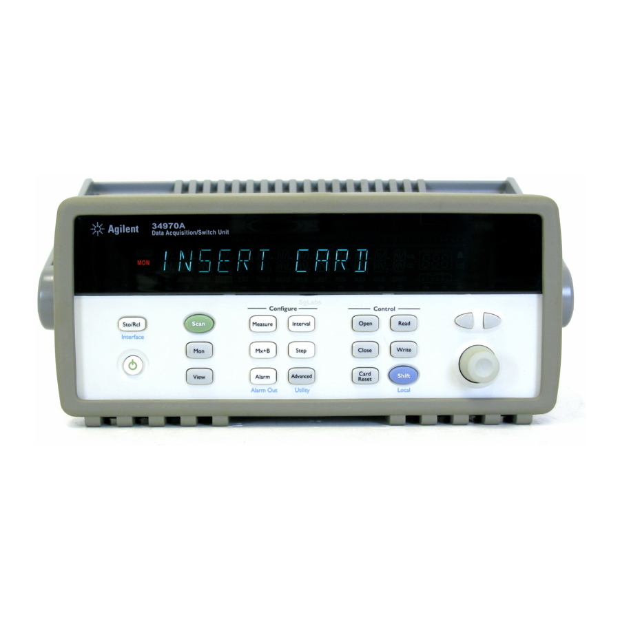
User Manuals: HP 34970A Acquisition Switch Unit
Manuals and User Guides for HP 34970A Acquisition Switch Unit. We have
1
HP 34970A Acquisition Switch Unit manual available for free PDF download: User Manual
HP 34970A User Manual (429 pages)
Data Acquisition / Switch Unit
Brand:
HP
| Category:
Switch
| Size: 10 MB
Table of Contents
The Front Panel at a Glance
3
The Front-Panel Menus at a Glance
4
Display Annunciators
5
The Rear Panel at a Glance
6
The Plug-In Modules at a Glance
8
In this Book
11
Table of Contents
12
Chapter 1 Quick Start
16
Installing HP Benchlink Data Logger Software
17
To Connect Wiring to a Module
17
To Set the Time and Date
17
To Prepare the Instrument for Use
17
Installing HP Benchlink Data Logger Software
19
Installation Procedure
19
Chapter 1 Quick Start to Connect Wiring to a Module
21
To Connect Wiring to a Module
21
Chapter 1 Quick Start to Set the Time and Date
23
To Set the Time and Date
23
To Configure a Channel for Scanning
24
Chapter 1 Quick Start to Configure a Channel for Scanning
25
To Copy a Channel Configuration
26
Chapter 1 Quick Start to Close a Channel
27
To Close a Channel
27
If the Instrument Does Not Turn on
28
Chapter 1 Quick Start if the Instrument Does Not Turn on
29
To Adjust the Carrying Handle
30
Chapter 1 Quick Start to Rack Mount the Instrument
31
To Rack Mount the Instrument
31
Chapter 2 Front-Panel Overview
33
Front-Panel Menu Reference
35
Chapter 2 Front-Panel Overview to Monitor a Single Channel
37
To Monitor a Single Channel
37
Chapter 2 Front-Panel Overview to Set a Scan Interval
38
To Set a Scan Interval
38
Chapter 2 Front-Panel Overview to Apply MX+B Scaling to Measurements
39
To Apply MX+B Scaling to Measurements
39
Chapter 2 Front-Panel Overview to Configure Alarm Limits
40
To Configure Alarm Limits
40
Chapter 2 Front-Panel Overview to Read a Digital Input Port
42
To Read a Digital Input Port
42
Chapter 2 Front-Panel Overview to Write to a Digital Output Port
43
To Write to a Digital Output Port
43
Chapter 2 Front-Panel Overview to Read the Totalizer Count
44
To Read the Totalizer Count
44
Chapter 2 Front-Panel Overview to Output a DC Voltage
45
To Output a DC Voltage
45
Chapter 2 Front-Panel Overview to Configure the Remote Interface
46
To Configure the Remote Interface
46
Chapter 2 Front-Panel Overview to Store the Instrument State
48
To Store the Instrument State
48
Chapter 3 System Overview
49
Data Acquisition System Overview
50
Measurement Software
52
Plug-In Modules
54
System Cabling
55
Transducers and Sensors
56
Chapter 3 System Overview Signal Routing and Switching
57
Signal Routing and Switching
57
Switching Topologies
57
Chapter 3 System Overview Measurement Input
60
Measurement Input
60
The Internal DMM
60
Scanning with External Instruments
64
Chapter 3 System Overview Control Output
67
Control Output
67
Features and Functions
70
SCPI Language Conventions
71
Chapter 4 Features and Functions
72
SCPI Language Conventions
72
Rules for Using a Channel List
72
Scanning
73
Rules for Scanning
73
Power Failure
76
Adding Channels to a Scan List
77
Scan Interval
79
Scan Count
85
Reading Format
86
Channel Delay
87
Automatic Channel Delays
88
Viewing Readings Stored in Memory
89
Single-Channel Monitoring
92
Scanning with External Instruments
94
General Measurement Configuration
97
Measurement Range
97
Measurement Resolution
99
Custom A/D Integration Time
102
Temperature Measurement Configuration
105
Measurement Units
105
Thermocouple Measurements
106
RTD Measurements
109
Thermistor Measurements
111
Voltage Measurement Configuration
112
DC Input Resistance
112
Voltage Measurement Configuration
113
AC Low Frequency Filter
113
Resistance Measurement Configuration
114
Offset Compensation
114
Current Measurement Configuration
115
Frequency Measurement Configuration
117
Low Frequency Timeout
117
MX+B Scaling
118
Alarm Limits
121
Viewing Stored Alarm Data
125
Using the Alarm Output Lines
127
Digital Input Operations
132
Digital Input Operations
133
Totalizer Operations
134
Digital Output Operations
137
DAC Output Operations
138
System-Related Operations
139
State Storage
139
Error Conditions
141
Display Control
143
Real-Time System Clock
144
Internal DMM Disable
144
Firmware Revision Query
145
Relay Cycle Count
146
Remote Interface Configuration
149
Remote Interface Configuration
150
Remote Interface Selection
150
Baud Rate Selection (RS-232)
151
Parity Selection (RS-232)
151
Calibration Overview
154
Calibration Security
154
Calibration Overview
155
Calibration Message
157
Calibration Count
158
Factory Reset State
159
Instrument Preset State
160
Multiplexer Module Default Settings
161
Module Overview
162
HP 34901A 20-Channel Multiplexer
163
HP 34902A 16-Channel Multiplexer
165
HP 34903A 20-Channel Actuator
167
HP 34904A 4X8 Matrix Switch
169
HP 34904A 4X8 Matrix Switch
170
HP 34905A/6A Dual 4-Channel RF Multiplexers
171
HP 34907A Multifunction Module
173
Digital Input/Output
173
HP 34908A 40-Channel Single-Ended Multiplexer
175
Chapter 5 Remote Interface Reference
177
Remote Interface Reference
178
SCPI Command Summary
179
SCPI Command Summary, Starting
179
SCPI Command Summary
181
Voltage Configuration Commands
186
Resistance Configuration Commands
187
Current Configuration Commands
188
Digital Input Commands
192
Digital Output Commands
192
DAC Output Commands
193
Switch Control Commands
193
State Storage Commands
194
Interface Configuration Commands
196
Simplified Programming Overview
199
Using the Measure? Command
200
Using the Configure Command
200
Using the READ? Command
202
Using the Initiate and Fetch? Commands
202
The Measure? and Configure Commands
205
Setting the Function, Range, and Resolution
212
Temperature Configuration Commands
217
Temperature Configuration Commands
219
Voltage Configuration Commands
221
Resistance Configuration Commands
222
Current Configuration Commands
222
Frequency Configuration Commands
223
Scanning Overview
224
Single-Channel Monitoring Overview
235
Scanning with an External Instrument
237
MX+B Scaling Overview
242
Alarm System Overview
245
Alarm System Overview
247
Digital Input Commands
253
Totalizer Commands
254
Digital Output Commands
256
DAC Output Commands
256
Switch Control Commands
257
State Storage Commands
259
System-Related Commands
262
Interface Configuration Commands
267
Interface Configuration
268
Configuration Overview
268
Flow Control Modes
269
RS-232 Interface Configuration
270
Data Frame Format
270
Connection to a Computer or Terminal
270
Troubleshooting
271
Modem Communications
272
The SCPI Status System
273
What Is a Condition Register
273
What Is an Event Register
273
What Is an Enable Register
273
The Status Byte Register
275
Using Service Request (SRQ) and Serial Poll
276
Using *STB? to Read the Status Byte
276
To Interrupt Your Bus Controller Using SRQ
277
To Determine When a Command Sequence Is Completed
277
The Standard Event Register
280
Status System Commands
284
Calibration Commands
290
Service-Related Commands
292
An Introduction to the SCPI Language
294
Command Format Used in this Manual
295
An Introduction to the SCPI Language
296
Command Separators
296
Using the MIN and MAX Parameters
296
Querying Parameter Settings
297
SCPI Command Terminators
297
IEEE-488.2 Common Commands
297
SCPI Parameter Types
298
Using Device Clear
300
Chapter 6 Error Messages
301
Error Messages
302
Execution Errors
303
Execution Errors
305
Error Messages Instrument Errors
307
Instrument Errors
307
Chapter 6 Error Messages Self-Test Errors
312
Self-Test Errors
312
Chapter 6 Error Messages Calibration Errors
313
Calibration Errors
313
Chapter 6 Error Messages Plug-In Module Errors
315
Plug-In Module Errors
315
Chapter 7 Application Programs
316
Application Programs
317
Example Programs for Excel 7.0
318
Chapter 7 Application Programs Example Programs for C and C
325
Example Programs for C and C
325
Chapter 8 Tutorial
329
Chapter 8 Tutorial System Cabling and Connections
331
System Cabling and Connections
331
Cable Specifications
331
Grounding Techniques
333
System Cabling and Connections
335
Chapter 8 Tutorial Measurement Fundamentals
339
Measurement Fundamentals
339
Temperature Measurements
341
DC Voltage Measurements
350
AC Voltage Measurements
355
Current Measurements
363
Resistance Measurements
365
Frequency and Period Measurements
372
Chapter 8 Tutorial Low-Level Signal Multiplexing and Switching
374
Low-Level Signal Multiplexing
374
Chapter 8 Tutorial Actuators and General-Purpose Switching
380
Actuators and General-Purpose Switching
380
Chapter 8 Tutorial Matrix Switching
384
Matrix Switching
384
Chapter 8 Tutorial RF Signal Multiplexing
386
RF Signal Multiplexing
386
Chapter 8 Tutorial Multifunction Module
388
Multifunction Module
388
Digital Input
388
Digital Output
389
Multifunction Module
392
Voltage (DAC) Output
393
Chapter 8 Tutorial Relay Life and Preventative Maintenance
395
Relay Life and Preventative Maintenance
395
Switching Frequency
397
Replacement Strategy
397
Measurement Rates and System Characteristics
398
Specifications DC, Resistance, and Temperature Accuracy Specifications
399
DC, Resistance, and Temperature Accuracy Specifications
399
DC Measurement and Operating Characteristics
400
AC Measurement and Operating Characteristics
400
Chapter 9 Specifications AC Accuracy Specifications
401
AC Accuracy Specifications
401
Chapter 9 Specifications AC Measurement and Operating Characteristics
402
AC Measurement and Operating Characteristics
402
Chapter 9 Specifications Measurement Rates and System Characteristics
403
Measurement Rates and System Characteristics
403
Module Specifications HP 34901A, 34902A, 34908A, 34903A, 34904A
404
Chapter 9 Specifications Module Specifications
404
Hp 34905A, 34906A
405
Chapter 9 Specifications Typical AC Performance Graphs
406
Typical AC Performance Graphs
406
Hp 34907A
407
Software Specifications
407
Chapter 9 Specifications Product and Module Dimensions
408
Product and Module Dimensions
408
Chapter 9 Specifications to Calculate Total Measurement Error
409
To Calculate Total Measurement Error
409
Interpreting Internal DMM Specifications
411
Temperature Coefficients
413
Chapter 9 Specifications Configuring for Highest Accuracy Measurements
414
Configuring for Highest Accuracy Measurements
414
Index
415
Declaration of Conformity
428
Advertisement
Advertisement
Related Products
HP ProCurve 3400cl-24G
HP ProCurve 3400cl-48G
HP ProCurve Series 3400cl
HP StorageWorks 344181-B21
HP ProCurve 3500yl-24G-PoE+
HP 3100-16 v2 SI
HP 3600-48-PoE+ v2 EI
HP 3600-24-PoE+ v2 SI
HP 3235
HP IntelliJack 3CNJ2000G
HP Categories
Desktop
Laptop
Server
Monitor
Switch
More HP Manuals
Login
Sign In
OR
Sign in with Facebook
Sign in with Google
Upload manual
Upload from disk
Upload from URL