Sign In
Upload
Manuals
Brands
Honeywell Manuals
Control Panel
NOTIFIER NFW-50X
User Manuals: Honeywell NOTIFIER NFW-50X Control Panel
Manuals and User Guides for Honeywell NOTIFIER NFW-50X Control Panel. We have
2
Honeywell NOTIFIER NFW-50X Control Panel manuals available for free PDF download: Manual
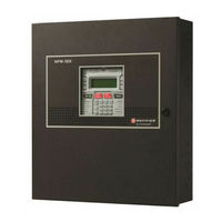
Honeywell NOTIFIER NFW-50X Manual (164 pages)
Brand:
Honeywell
| Category:
Control Panel
| Size: 2 MB
Table of Contents
Installation Precautions
3
FCC Warning
3
Software Downloads
4
Documentation Feedback
4
Table of Contents
5
Section 1: Product Description
12
Features and Options
12
Specifications
13
Controls and Indicators
14
Components
15
1: Intelligent Addressable Detectors
16
2: Intelligent Addressable Modules
16
3: Addressable Device Accessories
16
End-Of-Line Resistor Assembly
16
Power Supervision Relay
16
EOL-C(R/W) Mounting Plate
16
Optional Modules
16
Accessories
16
1: FS-Tools Programming Utility
16
2: Dress Panel
17
3: Trim Ring
17
4: Battery Box
17
Nfs-Lbb
17
5: Battery Charger
17
6: FWSG Wireless Gateway
17
7: ANN-BUS Annunciators/Modules
18
Guidelines
18
N-ANN-80 and N-ANN-100 Remote Fire Annunciators
18
N-ANN-S/PG Serial/Parallel Interface Module
18
N-ANN-I/O LED Driver Module
18
N-ANN-LED Annunciator Module
18
N-ANN-RLY Annunciator Module
18
Getting Started
19
Telephone Requirements and Warnings
19
1: Telephone Circuitry
19
2: Telephone Company Rights and Warnings
19
Section 2: Installation
21
Mounting the Backbox
21
Power
24
1: AC Power and Earth Ground Connection
24
2: Battery Power
24
3: Special Application DC Power Output Connection
25
Relays
25
Notification Appliance Circuits
25
1: Class B NAC Wiring
26
2: Class a NAC Wiring
26
Remote Synchronization Output
27
UL Power-Limited Wiring Requirements
28
IPOTS-COM Communicator
29
Wiring
29
Dip Switches
29
Optional Module Installation
30
1: Cell-Mod/Cell-Cab-N
30
Installation
30
Wiring
30
2: 4XTM Transmitter Module Installation
30
3: ANN-BUS Annunciators/Modules
32
ANN-BUS Wiring
32
Calculating Wiring Distance for ANN-BUS Modules
32
Wiring Distance Calculation Example
33
Wiring Configuration
33
ANN-BUS Device Addressing
35
N-ANN-80 Remote Fire Annunciator
35
Specifications
35
Opening/Closing Annunciator
35
N-ANN-100 Remote Fire Annunciator
37
N-ANN-S/PG Serial/Parallel Interface Module
38
Setting Printer Options
39
Printer Installation
39
N-ANN-I/O LED Driver Module
40
N-ANN-LED Annunciator Module
42
N-ANN-RLY Annunciator Module
44
4: Printer
45
Printer Configuration
45
5: FWSG Wireless Gateway
46
Section 3: Programming
47
User Programming
48
Programming Screens Description
48
Initial Power-Up
48
Users and Passwords
48
1: Administrator Role
49
Password Change-Administrator
49
Password Change- User
50
Assign Role
51
2: User Role
52
Master Programming Level
52
1=Autoprogram
53
2: Point Program
54
Detector Programming
54
Module Programming
60
3=Zone Setup
68
Enable
68
Disable
68
Special Purpose Zone
69
Zones Installed
69
Zones Enabled
70
Zones Disabled
70
Zone Type
70
Zones Available
71
4: Loop Setup
71
Class
71
Loop Protocol
71
Device Addressing
71
5: System Setup
71
Function Keys
72
Banner
72
Time-Date
73
Timers
74
NACS (Notification Appliance Circuits)
76
Relays
79
Canadian Option
79
Waterflow Silenceable
80
Auxiliary Power
80
Trouble Reminder
80
Language
81
Charger Enable
81
4XTM Supervision
81
Remote Sync Enable
81
6: History
81
View Events
81
Erase History
81
7: Communicator
82
Communicator Installed
82
POTS Settings
82
IP Settings
83
Primary and Secondary Communication Paths
84
Trouble Report Limit (Dialer Runaway Prevention)
87
Report Style
87
Event Codes
87
8: Annunciators
90
ANN-BUS Setup
90
ANN-BUS Options
97
9: Password Change
99
Invalid Password
99
Incorrect Password/Timeout
99
10: Clear Program
100
11: Program Check
100
Maintenance Programming Level
101
1: Disable Point
101
2=History
101
3=Program Check
102
4: Walktest
103
5: System
103
6: Zone Setup
104
Section 4: Operating Instructions
106
Panel Control Buttons
106
1: Acknowledge
106
2: Alarm Silence
106
3: Drill/Hold 2 Sec
106
4: Reset
106
5: Function Keys F1-F4
106
LED Indicators
106
Maintenance
107
Normal Operation
107
Trouble Operation
107
Alarm Operation
108
CO Alarm Operation
109
Supervisory Operation
109
Process Monitor Operation
110
Hazard/Tornado Condition Operation
110
Medical Alert Condition Operation
110
NAC Operation
111
Programmed Zone Operation
111
Disable/Enable Operation
111
Waterflow Circuits Operation
111
Detector Functions
111
Time Functions: Real-Time Clock
111
Synchronized NAC Operation
111
Coded Operation
112
Presignal
112
Positive Alarm Sequence
112
Special System Timers
113
1: Silence Inhibit Timer
113
2: Autosilence Timer
113
3: Trouble Reminder
113
4: Waterflow Retard Timer
113
5: Alarm Verification (None or One Minute)
113
6: Control Module Delay Timer
113
Walktest
113
Read Status
114
1=System Point
114
2=Zones
115
3: Trouble Reminder
115
4: Timers
116
5: Nacs
116
6: Relays
116
7: Program Check
116
8: History
116
9: Annunciators
117
10: Communicator
117
11: Print
118
Chamber Value
119
Drift Compensation
119
Maintenance Alert
119
12: Time-Date
120
13: Battery Charger
120
14: 4XTM Supervision
120
15: Remote Sync
120
Section 5: Central Station Communications - POTS Transmission
121
Transmittal Priorities
121
Section 6: FS-Tools Upload/Download
123
FS-Tools Up/Download
123
Transferring a Program
123
1: Security Features
124
Secret Code Verification
124
Time-Out at Control Panel
124
Error Checking
124
Central Station Data Protection
124
Section 7: USB Upload/Download
125
USB Upload/Download
125
Section 8: Firmware Upgrade
127
Firmware Upgrade
127
Section 9: Power Supply Calculations
129
Overview
129
Calculating the AC Branch Circuit
129
Calculating the System Current Load
129
2: How to Calculate System Current Load
129
Calculating the Battery Size
131
1: NFPA Battery Requirements
131
2: Selecting and Locating Batteries
131
Appendix A: Software Zones
132
A.1: Correlations
132
Appendix B: Default Programming
137
Appendix C: NFPA Standard-Specific Requirements
138
C.1: MBT-1 Municipal Box Trip - Silenceable
141
Appendix D: Wire Requirements
142
D.1: NAC Wiring
143
Appendix E: HVAC Control
144
E.1: Control Module Operation
144
E.1.1: Hvac Shutdown
144
E.2: Monitor Module Operation
145
E.2.1: Hvac Restart
145
E.2.2: Hvac Ovrride
145
Appendix F: Ademco Contact ID Format Event Code Descriptions
146
F.1: Transmission Format between DACT and Receiver
146
F.2: Ademco Contact ID Typical Printout
146
Appendix G: Central Station Points
151
Appendix H: NFPA Requirements
152
Appendix I: Open/Short/Ground Trip Values
153
Index
154
Slide-In Labels
159
NFW-50X Fire Alarm Control Panel Operating Instructions
161
Manufacturer Warranties and Limitation of Liability
163
Advertisement
Honeywell NOTIFIER NFW-50X Manual (158 pages)
Addressable Fire Alarm Control Panel
Brand:
Honeywell
| Category:
Control Panel
| Size: 2 MB
Table of Contents
Table of Contents
5
Section 1: Product Description
12
Features and Options
12
Specifications
13
Controls and Indicators
14
Components
15
1: Intelligent Addressable Detectors
16
2: Intelligent Addressable Modules
16
3: Addressable Device Accessories
16
End-Of-Line Resistor Assembly
16
Power Supervision Relay
16
EOL-C(R/W) Mounting Plate
16
Optional Modules
16
Accessories
16
1: FS-Tools Programming Utility
16
2: Dress Panel
17
3: Trim Ring
17
4: Battery Box
17
Nfs-Lbb
17
5: Battery Charger
17
6: FWSG Wireless Gateway
17
7: ANN-BUS Annunciators/Modules
18
Guidelines
18
N-ANN-80 and N-ANN-100 Remote Fire Annunciators
18
N-ANN-S/PG Serial/Parallel Interface Module
18
N-ANN-I/O LED Driver Module
18
N-ANN-LED Annunciator Module
18
N-ANN-RLY Annunciator Module
18
Getting Started
19
Telephone Requirements and Warnings
19
1: Telephone Circuitry
19
2: Telephone Company Rights and Warnings
19
Section 2: Installation
20
Mounting the Backbox
20
Power
23
1: AC Power and Earth Ground Connection
23
2: Battery Power
23
3: Special Application DC Power Output Connection
24
Relays
24
Notification Appliance Circuits
24
1: Class B NAC Wiring
25
2: Class a NAC Wiring
25
Remote Synchronization Output
26
UL Power-Limited Wiring Requirements
27
IPOTS-COM Communicator
28
Wiring
28
Dip Switches
28
Optional Module Installation
29
1: Cell-Mod/Cell-Cab-N
29
Installation
29
Wiring
29
2: 4XTM Transmitter Module Installation
29
3: ANN-BUS Annunciators/Modules
31
ANN-BUS Wiring
31
ANN-BUS Device Addressing
34
N-ANN-80 Remote Fire Annunciator
34
N-ANN-100 Remote Fire Annunciator
36
N-ANN-S/PG Serial/Parallel Interface Module
37
N-ANN-I/O LED Driver Module
39
N-ANN-LED Annunciator Module
41
N-ANN-RLY Annunciator Module
43
4: Printer
44
Printer Configuration
44
5: FWSG Wireless Gateway
45
Section 3: Programming
46
Programming Data Entry
46
User Programming
47
Initial Power-Up
48
Programming Screens Description
48
Programming and Passwords
48
Master Programming Level
49
1=Autoprogram
49
2: Point Program
50
Detector Programming
50
Module Programming
56
3=Zone Setup
65
Enable
65
Disable
65
Special Purpose Zone
65
Zones Installed
66
Zones Enabled
66
Zones Disabled
66
Zone Type
67
Zones Available
67
4: Loop Setup
67
Class
68
Loop Protocol
68
Device Addressing
68
5: System Setup
68
Function Keys
69
Banner
69
Time-Date
70
Timers
71
NACS (Notification Appliance Circuits)
72
Relays
75
Canadian Option
75
Waterflow Silenceable
76
Auxiliary Power
76
Trouble Reminder
76
Language
76
Charger Enable
76
4XTM Supervision
76
Remote Sync Enable
76
6: History
77
View Events
77
Erase History
77
7: Communicator
77
Communicator Installed
77
POTS Settings
78
IP Settings
79
Primary and Secondary Communication Paths
80
Trouble Report Limit (Dialer Runaway Prevention)
82
Report Style
83
Event Codes
83
8: Annunciators
86
ANN-BUS Setup
86
ANN-BUS Options
93
9: Password Change
95
Invalid Password
95
10: Clear Program
96
11: Program Check
96
Maintenance Programming Level
97
1: Disable Point
97
2=History
97
3=Program Check
98
4: Walktest
99
5: System
99
6: Zone Setup
100
Section 4: Operating Instructions
102
Panel Control Buttons
102
1: Acknowledge
102
2: Alarm Silence
102
3: Drill/Hold 2 Sec
102
4: Reset
102
5: Function Keys F1-F4
102
LED Indicators
102
Normal Operation
103
Trouble Operation
103
Alarm Operation
104
CO Alarm Operation
105
Supervisory Operation
105
Process Monitor Operation
106
Hazard/Tornado Condition Operation
106
Medical Alert Condition Operation
106
NAC Operation
107
Programmed Zone Operation
107
Disable/Enable Operation
107
Waterflow Circuits Operation
107
Detector Functions
107
Time Functions: Real-Time Clock
107
Synchronized NAC Operation
107
Coded Operation
108
Presignal
108
Positive Alarm Sequence
108
Special System Timers
109
1: Silence Inhibit Timer
109
2: Autosilence Timer
109
3: Trouble Reminder
109
4: Waterflow Retard Timer
109
5: Alarm Verification (None or One Minute)
109
6: Control Module Delay Timer
109
Walktest
109
Read Status
110
1=System Point
110
2=Zones
111
3: Trouble Reminder
111
4: Timers
112
5: Nacs
112
6: Relays
112
7: Program Check
112
8: History
112
9: Annunciators
113
10: Communicator
113
11: Print
114
Chamber Value
115
Drift Compensation
115
Maintenance Alert
115
12: Time-Date
116
13: Battery Charger
116
14: 4XTM Supervision
116
15: Remote Sync
116
Section 5: Central Station Communications - POTS Transmission
117
Transmittal Priorities
117
Section 6: FS-Tools Upload/Download
119
FS-Tools Up/Download
119
Transferring a Program
119
1: Security Features
120
Secret Code Verification
120
Time-Out at Control Panel
120
Error Checking
120
Central Station Data Protection
120
Section 7: USB Upload/Download
121
USB Upload/Download
121
Section 8: Firmware Upgrade
123
Firmware Upgrade
123
Section 9: Power Supply Calculations
125
Overview
125
Calculating the AC Branch Circuit
125
Calculating the System Current Load
125
2: How to Calculate System Current Load
125
Calculating the Battery Size
127
1: NFPA Battery Requirements
127
2: Selecting and Locating Batteries
127
Appendix A: Software Zones
128
A.1: Correlations
128
Appendix B: Default Programming
133
Appendix C: NFPA Standard-Specific Requirements
134
C.1: MBT-1 Municipal Box Trip - Silenceable
137
Appendix D: Wire Requirements
138
D.1: NAC Wiring
139
Appendix E: HVAC Control
140
E.1: Control Module Operation
140
E.1.1: Hvac Shutdown
140
E.2: Monitor Module Operation
141
E.2.1: Hvac Restart
141
E.2.2: Hvac Ovrride
141
Appendix F: Ademco Contact ID Format Event Code Descriptions
142
F.1: Transmission Format between DACT and Receiver
142
F.2: Ademco Contact ID Typical Printout
142
Appendix G: NFPA Requirements
147
Appendix H: Open/Short/Ground Trip Values
148
Index
149
Slide-In Labels
153
NFW-50X Fire Alarm Control Panel Operating Instructions
155
Advertisement
Related Products
Honeywell NOTIFIER NFW-100X
Honeywell NOTIFIER NFW-100XI
Honeywell Notifier NFW-50XI
Honeywell nfs2-3030
Honeywell Notifier NFS-320
Honeywell Notifier NFS-320SYS
Honeywell Notifier NFS-320SYS/E
Honeywell NOTIFIER NFS-640
Honeywell Notifier NFS-320/E/C
Honeywell NOTIFIER NCA-2
Honeywell Categories
Thermostat
Controller
Control Unit
Security Camera
Security System
More Honeywell Manuals
Login
Sign In
OR
Sign in with Facebook
Sign in with Google
Upload manual
Upload from disk
Upload from URL