Sign In
Upload
Manuals
Brands
Generac Power Systems Manuals
Inverter
9 kW NG
Generac Power Systems 9 kW NG Manuals
Manuals and User Guides for Generac Power Systems 9 kW NG. We have
5
Generac Power Systems 9 kW NG manuals available for free PDF download: Repair Manual, Installation Manuallines, Owner's Manual
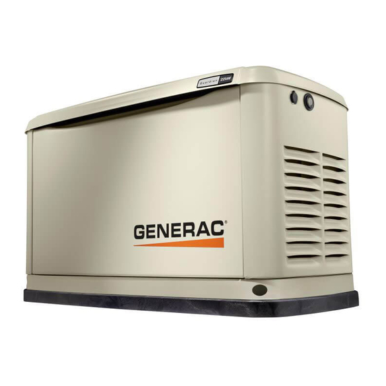
Generac Power Systems 9 kW NG Repair Manual (192 pages)
automatic standby generators
Brand:
Generac Power Systems
| Category:
Inverter
| Size: 19.43 MB
Table of Contents
Electrical Formulas
2
Table of Contents
3
Specifications
6
Generator
6
Engine
7
Fuel Consumption
7
Mounting Dimensions
8
Mounting Dimensions
9
Major Features
10
Part 1 - General Information
11
Part 1 - General Information
12
Generator Identification
12
Introduction
12
Installation Basics
13
Introduction
13
Selecting a Location
13
Grounding the Generator
13
The Fuel Supply
13
The Transfer Switch / Load Center
13
Power Source and Load Lines
15
System Control Interconnections
15
Natural Gas Fuel Interconnections
15
Non-Prepackaged Interconnections
16
Connect a Pre-2008 Load Center Switch to a Current or Future Air-Cooled Generator
16
Connect a 2008 and Later Load Center Switch to a Pre-2008 Air-Cooled Generator
17
Preparation before Use
18
General
18
Fuel Requirements
18
Fuel Consumption
18
Reconfiguring the Fuel System
18
Engine Oil Recommendations
20
Testing, Cleaning and Drying
21
Meters
21
The vom
21
Measuring AC Voltage
21
Measuring DC Voltage
21
Measuring AC Frequency
21
Measuring Current
22
Measuring Resistance
22
Electrical Units
23
Ohm's Law
23
Visual Inspection
24
Insulation Resistance
24
The Megohmmeter
24
Stator Insulation Resistance Test (12-20 Kw)
25
Stator Insulation Resistance Test (8-10 Kw)
25
Rotor Insulation Resistance Test (8-10 Kw)
26
Rotor Insulation Resistance Test (12-20 Kw)
26
Cleaning the Generator
26
Drying the Generator
26
Engine-Generator Protective Devices
27
General
27
Low Battery
27
Low Oil Pressure Shutdown
27
High Temperature Switch
27
Overspeed Shutdown
27
Rpm Sensor Failure
27
Overcrank Shutdown
28
Failure to Start
28
Cranking CONDITIONS
28
Operating Instructions
29
Control Panel
29
To Select Automatic Operation
30
Manual Transfer to "Standby" and Manual Startup
30
Manual Shutdown and Retransfer Back to "Utility
30
Automatic Operating Parameters
31
Introduction
31
Automatic Operating Sequences
31
Part 2 - Ac Generators
33
Description and Components
34
Introduction
34
Engine-Generator Drive System
34
The AC Generator
34
Rotor Assembly
34
Stator Assembly
35
Brush Holder and Brushes (12-20 Kw)
36
Other AC Generator Components
36
Operational Analysis
37
Rotor Residual Magnetism
37
Field Boost (12-20 Kw)
37
Field Boost (12-20 Kw Units)
37
Operation (8/10 Kw)
38
Operation (12-20 Kw)
38
Troubleshooting Flowcharts
39
Problem 1 - Generator Produces Zero Voltage or Residual Voltage (12-20 Kw)
39
Problem 2 - Generator Produces Zero Voltage or Residual Voltage (8/10 Kw)
40
Problem 2 - Generator Produces Zero Voltage or Residual Voltage 8/10 Kw
40
Problem 1 - Generator Produces Zero Voltage or Residual Voltage 12-20 Kw
40
Problem 3 - Generator Produces Low Voltage at No-Load
41
Problem 4 - Generator Produces High Voltage at No-Load
41
Problem 5 - Voltage and Frequency Drop Excessively When Loads Are Applied
42
Diagnostic Tests
43
Introduction
43
Safety
43
Test 1 - Check Main Circuit Breaker
43
Test 2 - Check AC Output Voltage
43
Test 4 - Fixed Excitation Test/Rotor
44
Amp Draw Test
44
Test 5 - Wire Continuity (12-20 Kw)
45
Test 6 - Check Field Boost (12-20 Kw)
46
Test 7 - Testing the Stator with a vom
46
(12-20 Kw)
46
Test 8 - Test Brushless Stator
47
Test 9 - Check Capacitor
48
Test 10 - Test DPE Winding on
49
Brushless Units
49
Test 11 - Resistance Check of Rotor Circuit (12-20 Kw)
50
Test 12 - Check Brushes and Slip Rings
50
(12-20 Kw)
51
Test 13 - Test Rotor Assembly(12-20 Kw)
51
Test 14 - Check AC Output Frequency
51
Test 15 - Check and Adjust Engine Governor (Single Cylinder Units)
51
Test 16 - Check Stepper Motor Control
52
(V-Twin Engine Units)
52
Test 17 - Check and Adjust Voltage
53
Regulator (12-20 Kw)
53
Test 18 - Check Voltage and Frequency
54
Under Load
54
Test 19 - Check for Overload Condition
54
Test 20 - Check Engine Condition
54
Test 21 - Field Flash Alternator (8-10 Kw)
54
Part 3 - Transfer Switch
57
Description and Components
58
General
58
Enclosure
58
Transfer Mechanism
59
Transfer Relay
59
Neutral Lug
60
Manual Transfer Handle
60
Terminal Block
60
Fuse Holder
61
Operational Analysis
62
Utility Source Voltage Available
64
Utility Source Voltage Failure
65
Transfer to Standby
66
Transfer to Standby
67
Utility Restored
68
Utility Restored, Transfer Switch De-Energized
69
De-Energized
69
Utility Restored, Retransfer Back to Utility
70
Transfer Switch in Utility
71
Troubleshooting Flowcharts
72
Introduction to Troubleshooting
72
Problem 7 - in Automatic Mode, no Transfer to Standby
72
During Exercise or in Manual Mode
73
Problem 9 - Blown F1 or F2 Fuse
73
Manual Mode
73
Problem 10 - Units Starts and Transfer Occurs When Utility Power Is on
74
Problem 11 - no Battery Charge (Pre-Packed Load Center)
75
Problem 12 - no Battery Charge (RTSN & RTSE Transfer Switch)
75
Problem 12 - no Battery Charge (RTSN + RTSE Transfer Switch)
75
Problem 13 - no Battery Charge (Gen-Ready Load Center)
75
Problem 14 - no Battery Charge (Load Shed Transfer Switch)
75
Diagnostic Tests
76
General
76
Test 26 - Check Voltage at Terminal Lugs E1, E2
76
Test 27 - Check Manual Transfer Switch Operation
77
Operation
77
Test 28 - Check 23 and 15B
78
Wiring/Connections
78
Test 29 - Test Transfer Relay TR
79
Test 30 - Standby Control Circuit
80
Test 31 - Check Wire 23
80
Test 32 - Utility Control Circuit
82
Test 33 - Test Limit Switch SW2 and SW3
84
Test 34 - Check Fuses F1 and F2
84
Test 35 - Check N1 and N2 Wiring
85
Test 36 - Check N1 and N2 Voltage
85
Test 37 - Check Utility Sensing Voltage
86
At the Circuit Board
86
Test 38 - Check Utility Sense Voltage
86
Test 39 - Check Voltage at Terminal Lugs N1, N2
86
Test 40 - Check Battery Charger Supply
88
Voltage "Pre-Wire Load Center
88
Test 41 - Check Battery Charger Output
88
Test 42 - Check Wire 0 and Wire15B
88
Pre-Wire Load Center
88
Test 43 - Check Battery Charger
89
Supply Voltage "RTSN & RTSE Transfer Switch
89
RTSN & RTSE Transfer Switch
89
Test 44 - Check Battery Charger
89
Output Voltage "RTSN & RTSE Transfer Switch
89
Test 45 - Check Wire
89
Test 46 - Check Battery Charger
92
Supply Voltage "Genready Load Center
92
Test 47 - Check Battery Charger
92
Output Voltage "Genready Load Center
92
Test 48 - Check Wire 0/15B
92
Genready Load Center
92
Test 49 - Check Battery Charger
94
Supply Voltage "Load Shed Transfer Switch
94
Test 50 - Check Battery Charger
94
Output Voltage "Load Shed Transfer Switch
94
Test 51 - Check Wire 0 and Wire 15B
96
Load Shed Transfer Switch
96
Part 4 - DC Control
97
Part 4 - DC Control
98
Description and Components
98
General
98
Terminal Strip / Interconnection Terminal
98
Circuit Board
98
Auto-Off-Manual Switch
98
Amp Fuse
98
Amp Fuse
99
Menu System Navigation
104
Operational Analysis
106
Introduction
106
Utility Source Voltage Available
106
Initial Dropout of Utility Source Voltage
108
Utility Voltage Dropout and Engine Cranking
110
Engine Startup and Running
112
Initial Transfer to the "Standby" Source
114
Utility Voltage Restored / Re-Transfer to Utility
116
Engine Shutdown
118
Troubleshooting Flowcharts
120
Problem 15 - Engine will Not Crank When Utility Power Source Fails
120
Problem 16 - Engine will Not Crank When AUTO-OFF-MANUAL Switch Is Set to "MANUAL
120
Problem 17 - Engine Cranks but Won't Start
121
Problem 18 - Engine Starts Hard and Runs Rough / Lacks Power / Backfires
122
Problem 19 - Shutdown Alarm / Fault Occurred
123
Problem 20 - 7.5 Amp Fuse (F1) Blown
124
Problem 21 - Generator will Not Exercise
124
Problem 22 - no Low Speed Exercise
124
Diagnostic Tests
125
Introduction
125
Test 56 - Check Position of Auto-Off- Manual Switch
125
Test 57 - Try a Manual Start
125
Test 58 - Auto-Off-Manual Switch
125
(V-Twin Only)
125
Test 59 - Test Auto Operations
126
Test 60 - Check 7.5 Amp Fuse
126
Test 61 - Check Battery
126
Test 62 - Check Wire 56 Voltage
128
Test 63 - Test Starter Contactor Relay
128
(V-Twin Only)
128
Test 64 - Test Starter Contactor
129
(Single Cylinder Engine)
129
Test 65 - Test Starter Motor
130
Test 66 - Check Fuel Supply and Pressure
132
Test 67 - Check Circuit Board
133
Wire 14 Output
133
Test 68 - Check Fuel Solenoid
134
Test 69 - Check Choke Solenoid
134
Test 70 - Check for Ignition Spark
136
Test 71 - Check Spark Plugs
138
Test 72 - Check Engine / Cylinder Leak
138
Down Test / Compression Test
138
Test 73 - Check Shutdown Wire
139
Test 74 - Check and Adjust
140
Ignition Magnetos
140
Test 75 - Check Oil Pressure Switch
143
And Wire 86
143
Test 76 - Check High Oil
144
Temperature Switch
144
Test 77 - Check and Adjust Valves
144
Test 78 - Check Wire 18 Continuity
145
Test 79 - Test Exercise Function
146
Test 80 - Check Cranking and Running Circuits
146
Test 81 - Check to See if Low Speed
148
Function Is Enabled
148
Test 82 - Check Operation of the Choke Solenoid
148
Part 5 - Operational Tests
149
System Functional Tests
150
Introduction
150
Manual Transfer Switch Operation
150
Electrical Checks
150
Generator Tests under Load
151
Checking Automatic Operation
152
Setting the Exercise Timer
152
Part 6 - Disassembly
153
Major Disassembly
154
Front Engine Access
154
Major Disassembly
158
Torque Requirements
164
(Unless Otherwise Specified)
164
Part 7 - Electrical Data
165
Wiring Diagram, 8 Kw Home Standby
166
Schematic, 8 Kw Home Standby
168
Wiring Diagram, 10 Kw Home Standby
170
Schematic, 10 Kw Home Standby
172
Wiring Diagram, 14 Kw Home Standby
174
Schematic, 14 Kw Home Standby
176
Wiring Diagram, 17 Kw Home Standby
178
Schematic, 17 Kw Home Standby
180
Wiring Diagram, 20 Kw Home Standby
182
Schematic, 20 Kw Home Standby
184
Wiring Diagram, Home Standby Transfer Switch, 9/10/12/16 Circuit
186
Schematic, Home Standby Transfer Switch, 9/10/12/16 Circuit
188
Advertisement
Generac Power Systems 9 kW NG Installation Manuallines (68 pages)
Air-cooled generators
Brand:
Generac Power Systems
| Category:
Portable Generator
| Size: 4.19 MB
Table of Contents
English
2
Table of Contents
2
Introduction
2
Read this Manual Thoroughly
2
Contents
3
Operation and Maintenance
3
How to Obtain Service
3
Safety Rules
3
Standards Index
5
Unpacking/Inspection
5
NEC Requirement for Arc Fault Circuit Interruption Breaker for Bedrooms
5
Section 210.12 Arc Fault Circuit Interrupter Protection
5
Emission Information
6
Before You Begin
6
Site Preparation and Generator Placement
6
Coverting to LP Vapor
7
Installing & Connecting Gas Lines
8
External Electrical Connections
9
Generator Activation
10
Generator Connections - Transfer Switch
10
Appendix A - Setting the Automatic Exercise Function
12
Notes
13
Installation Diagrams
14
Electrical Data
16
Guías de Instalación
29
Español
30
Introducción
30
Lea Este Manual Completamente
30
Contenido
31
Operación y Mantenimiento
31
Cómo Obtener Servicio
31
Reglas de Seguridad
31
Índice de Estándares
33
Desempaque/Inspección
33
Requerimiento de NEC para Interrupción de Circuito por Falla de Arco Interruptor para Dormitorios
33
Sección 210.12 Protección de Interr de Circ por Falla de Arco
33
Antes de Empezar
34
Información de Emisiones
34
Preparación del Sitio y Ubicación del Generador
34
Conversión a Gas Licuado de Petróleo
35
Instalación y Conexión de Líneas de Gas
36
Conexiones Eléctricas Externas
37
Activación del Generador
38
Conexiones del Generador - Interruptor de Transferencia
38
Apéndice A - Fijando la Función de Ejercicio Automático
40
Notas
41
Consignes D'installation
43
Français
44
Introduction
44
Lire Attentivement Ce Manuel
44
Contenu
45
Fonctionnement Et Maintenance
45
Comment Obtenir L'entretien
45
Règles de Sécurité
45
Index des Normes
47
Déballage/ Inspection
47
Exigence du NEC en Matière de Disjoncteur D'interruption de Circuit de Défaut D'arc Pour Les Pièces Habitables
47
Protection de L'interrupteur de Circuit de Défaut D'arc de la Section 210.12
47
Avant de Commencer
48
Informations Relatives Aux Émissions
48
Préparation du Site Et Mise en Place du Générateur
48
Installation Et Raccordement des Canalisations de Gaz
50
Transformation en Vapeur de PL
50
Activation du Générateur
52
Branchements du Générateur - Commutateur de Transfert
52
Branchements Électriques Externes
52
Annexe A - Définition de la Fonction de Programme de Test Automatique
54
Remarques
55
Generac Power Systems 9 kW NG Owner's Manual (45 pages)
8 - 20kW Air-cooled, Automatic Standby Generators
Brand:
Generac Power Systems
| Category:
Portable Generator
| Size: 5.35 MB
Table of Contents
Table of Contents
2
Introduction
3
Read this Manual Thoroughly
3
Safety Rules
3
Contents
3
Operation and Maintenance
3
How to Obtain Service
3
Exhaust Hazards
4
Standards Index
5
Electrical Hazards
5
Explosion Hazards
5
General Information
6
Unpacking/Inspection
6
Protection Systems
6
NEC Requirement for Arc Fault Circuit
6
Interruption Breaker for Bedrooms
6
Emission Information
7
The Generator
8
Specifications
9
Ready to Run
10
Fuel Requirements and Recommendations
10
Fuel Consumption
10
Reconfiguring the Fuel System
11
High Altitude Operation
12
Location
12
Battery Requirements
15
Battery Installation
15
The Battery
15
Battery Charger
16
Post Installation Start-Up and Adjustments
16
Activate the Generator
16
Before Initial Startup
16
Check Transfer Switch Operation
16
Electrical Checks
16
Generator Tests under Load
18
Checking Automatic Operation
18
Operation
19
Control Panel Interface
19
Automatic Transfer Operation
20
Sequence of Automatic Operation
20
Manual Transfer Operation
21
Side Compartment
22
Protection Systems
22
Maintenance
24
Performing Scheduled Maintenance
24
Fuse
24
Checking the Engine Oil Level
24
Changing the Engine Oil
25
Changing the Engine Air Cleaner
25
Air Filter
26
Spark Plug(S)
26
Battery Maintenance
27
Adjusting Valve Clearance
27
Cooling System
28
Attention after Submersion
28
Corrosion Protection
28
Out of Service Procedure
28
Exhaust System
28
Service Schedule
30
Troubleshooting
31
Troubleshooting Guide
31
Appendix
32
Menu System Navigation
32
Notes
34
Installation Diagrams
35
Warranty
40
Emission Control System Warranty
41
Advertisement
Generac Power Systems 9 kW NG Owner's Manual (40 pages)
60 Hz Air-Cooled Generators 9kW to 22kW
Brand:
Generac Power Systems
| Category:
Portable Generator
| Size: 4.81 MB
Table of Contents
Table of Contents
3
Section 1: Safety Rules & General Information Introduction
5
Read this Manual Thoroughly
5
How to Obtain Service
5
Safety Rules
5
General Hazards
6
Exhaust Hazards
7
Electrical Hazards
7
Fire Hazards
8
Explosion Hazards
8
Section 2: General Information
9
The Generator
9
Specifications
11
Generator
11
Engine
11
Protection Systems
12
Emission Information
12
Fuel Requirements
12
Battery Requirements
12
Battery Charger
12
Engine Oil Requirements
12
Activating the Generator
13
Replacement Parts
13
Accessories
13
Section 3: Operation
15
Site Prep Verification
15
Generator Enclosure
15
Opening the Lid
15
Intake Side Panel Removal
16
Main Line Circuit Breaker (Generator Disconnect)
16
LED Indicator Lights
16
Control Panel Interface
17
Using the AUTO/OFF/MANUAL Interface
17
Interface Menu Displays
17
The LCD Panel
17
Menu System Navigation
18
Setting the Exercise Timer
20
Battery Charger
20
Manual Transfer Operation
21
Transfer to Generator Power Source
21
Transfer to Utility Power Source
22
Automatic Transfer Operation
22
Automatic Sequence of Operation
22
Utility Failure
22
Cranking
22
Cold Smart Start
23
Load Transfer
23
Shutting Generator down While under Load or During an Extended Outage
23
To Turn the Generator off
23
To Turn the Generator Back on
23
Section 4: Maintenance
25
Maintenance
25
Preparing for Maintenance
25
Performing Scheduled Maintenance
25
Service Schedule
26
Maintenance Log
26
Checking Engine Oil Level
27
Engine Oil Requirements
27
Changing the Oil and Oil Filter
28
Servicing the Air Cleaner
28
Spark Plugs
29
Valve Clearance Adjustment
29
Check Valve Clearance
29
Adjust Valve Clearance
29
Battery Maintenance
30
Cleaning the Sediment Trap
31
Attention after Submersion
31
Corrosion Protection
32
Remove From, and Return to Service
32
Remove from Service
32
Return to Service
32
Generac Power Systems 9 kW NG Installation Manuallines (60 pages)
Air-Cooled Generators. Single-cylinder GH-410 Engine; V-Twin GT-530 Engine; V-Twin GT-990 Engine; V-Twin GT-999 Engine
Brand:
Generac Power Systems
| Category:
Portable Generator
| Size: 8.39 MB
Table of Contents
Table of Contents
2
Introduction
2
Read this Manual Thoroughly
2
Contents
3
Operation and Maintenance
3
How to Obtain Service
3
Safety Rules
3
Electrical Hazards
4
Exhaust Hazards
4
Explosion Hazards
4
Fire Hazards
4
Standards Index
5
Unpacking/Inspection
5
Protection Systems
5
NEC Requirement for Arc Fault Circuit Interruption Breaker for Bedrooms
5
Section 210.12 Arc Fault Circuit Interrupter Protection
5
Emission Information
6
Before You Begin
6
Site Preparation and Generator Placement
6
Coverting to LP Vapor
7
Installing & Connecting Gas Lines
8
Battery Charger Installation
9
External Electrical Connections
10
Generator Connections - RTS Load Center Transfer Switch
10
Appendix A - RTS Pre-Wired Load Center Transfer Switch Installation & Operational Testing
12
Battery Installation
13
Operational Testing
14
Appendix B - RTSN Nd RTSE Transfer Switch Installation & Operational Testing
16
Selected Circuit Coverage
17
Whole-House Circuit Coverage
17
Battery Charger Installation
18
Electrical Connections
18
Operational Testing
19
Appendix C - Powermaster™ Load Controller Installation and Operationa Testing
21
Operational Testing
22
Checking the Priority Load Controller
25
Appendix D - Power Manager Load Shed Transfer Switch Installation and Operational Testing
26
Battery Charger Installation
27
Electrical Connections
27
Operational Testing
29
Verifying Load Shedding Operation
30
Appendix E - Genready Load Center Installation and Operational Testing
33
Battery Charger Installation
33
Electrical Connections
34
Operational Testing
35
Appendix F - Setting the Automatic Exercise Function
37
Notes
39
Electrical Data
42
Advertisement
Related Products
Generac Power Systems 91355
Generac Power Systems 9592-3
Generac Power Systems Air-cooled Recreational Vehicle Generator 9734-3
Generac Power Systems 9055-0
Generac Power Systems 9055-1
Generac Power Systems 9319-0
Generac Power Systems 9343-0
Generac Power Systems 9343-1
Generac Power Systems 9344-0
Generac Power Systems 9410-0
Generac Power Systems Categories
Portable Generator
Inverter
Pressure Washer
Switch
Lighting Equipment
More Generac Power Systems Manuals
Login
Sign In
OR
Sign in with Facebook
Sign in with Google
Upload manual
Upload from disk
Upload from URL