Fluke DTX-GFM2 Manuals
Manuals and User Guides for Fluke DTX-GFM2. We have 4 Fluke DTX-GFM2 manuals available for free PDF download: Technical Reference Handbook, User Manual
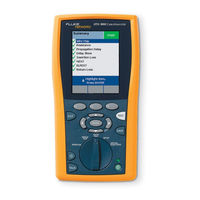
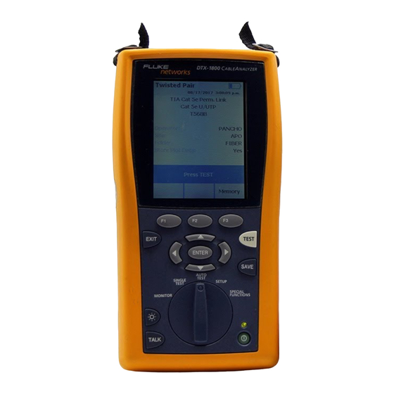
Fluke DTX-GFM2 Technical Reference Handbook (320 pages)
CableAnalyzer
Brand: Fluke
|
Category: Measuring Instruments
|
Size: 6 MB
Table of Contents
Advertisement
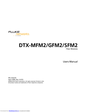
Fluke DTX-GFM2 User Manual (74 pages)
Fiber Modules
Brand: Fluke
|
Category: Control Unit
|
Size: 3 MB
Table of Contents

Advertisement
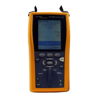
Fluke DTX-GFM2 User Manual (62 pages)
Fiber Modules
Brand: Fluke
|
Category: Control Unit
|
Size: 1 MB
Table of Contents
Advertisement