Sign In
Upload
Manuals
Brands
Festo Manuals
Controller
CMMD-AS series
Festo CMMD-AS series Manuals
Manuals and User Guides for Festo CMMD-AS series. We have
3
Festo CMMD-AS series manuals available for free PDF download: Description, Installation Manual, Manual
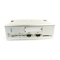
Festo CMMD-AS series Description (246 pages)
Motor controller
Brand:
Festo
| Category:
Controller
| Size: 2 MB
Table of Contents
Table of Contents
3
1 Safety and Requirements for Product Use
13
Safety
13
Safety Instructions
13
Intended Use
14
Requirements for Product Use
14
Gdcp-Cmms-As-G2-Hw
14
Gdcp-Cmms-As-G2-S1
14
Transport and Storage Conditions
15
Technical Requirements
15
Qualification of Trained Personnel
15
Range of Application and Certifications
15
2 Product Overview
16
Motor Controller CMMS-AS-C4-3A-G2
16
Control, Sensor and Safety Function Interfaces
16
Power Supply, Motor and Motor Encoder Interfaces
18
Parameter/Firmware Interfaces
20
LED Indicators, Seven-Segment Displays and DIL Switches
22
Motor Controller CMMS-ST-C8-7-G2
24
Control, Sensor and Safety Function Interfaces
24
Power Supply, Motor and Motor Encoder Interfaces
26
Parameter/Firmware Interfaces
28
LED Indicators, Seven-Segment Displays and DIL Switches
30
Motor Controller CMMD-AS-C8-3A
32
Control, Sensor and Safety Function Interfaces
32
Power Supply, Motor and Motor Encoder Interfaces
34
Parameter/Firmware Interfaces
36
LED Indicators, Seven-Segment Displays and DIL Switches
38
Control Interfaces - Operating Modes - Operational Functions
40
Overview: Control Interfaces/Connections/Device Profiles/ Operating Modes/Operational Functions
40
Positioning Mode: Direct Mode, Individual Record Mode, Record Linking Mode and Interpolated Positioning Mode
41
Positioning Mode: Homing Mode/Jog Mode/Teach Mode
42
Speed Mode, Force Mode and Torque Mode
43
Synchronisation
44
Operational Functions: Encoder Emulation, Flying Measurement, Analogue Monitor and Endless Positioning
45
3 Control Interfaces
46
Digital, Analogue, Synchronisation and Fieldbus Interfaces
46
Motor Controller CMMS-AS-C4-3A-G2
46
Motor Controller CMMS-ST-C8-7-G2
47
Motor Controller CMMD-AS-C8-3A
48
Digital Interfaces [X1] [X1.1/X1.2/EXT1/EXT2]
49
Digital I/O Modules (DIN
49
Selecting the Operating Mode/Mode Via Digital Input Signals
49
Digital Input/Output Signals as a Function of the Operating Mode/Mode
50
Digital Input Signals
52
Gdcp-CMMD-As-S1
52
Gdcp-Cmms-St-G2-S1
52
Gdcp-Cmms/D-C-Hp
52
Digital Output Signals
56
Cmms-St
57
Message "Target Reached
59
Message "Following Error
60
Message "Speed Reached
61
Message "Remaining Distance
64
Analogue Interface [X1] [X1.1/X1.2]
65
Analogue Input/Output (AIN0/AMON0)
65
Analogue Input Signal (Analogue Setpoint Value Specification)
65
Analogue Output Signal (Analogue Monitor)
66
Synchronisation Interfaces [X1/X10] [X1.1/X1.2/X10.1/X10.2]
67
Encoder Input for Synchronisation (Slave Interface)
67
Encoder Output for Encoder Emulation (Master Interface)
68
Incremental Signals (A/#A/B/#B/N/#N)
69
Pulse/Direction Signals (CLK/#CLK/DIR/#DIR)
70
Forward/Reverse Signals (CW/#CW/CCW/#CCW)
71
Fieldbus Interfaces [X4] [X5] [EXT/EXT1]
72
Supported Fieldbuses
72
Gdcp-Cmms/D-C-Co
72
Required Digital Inputs/Outputs with a Fieldbus Activation
73
Device Profiles for Fieldbuses
74
Device Profile: Festo Handling and Positioning Profile (FHPP)
74
Device Profile: Canopen, Cia 402 (for Electric Drives)
74
4 Measuring System
75
Measuring System for Electrical Drives
75
Measuring System for Linear Drives
75
Measuring System for Rotative Drives
76
Calculation Rules for the Measuring System
77
Limit Switch (Hardware) and Software End Position
77
Limit Switch LSN/LSP (Hardware)
77
Software End Position SLN/SLP
77
5 Commissioning
78
Configuration/Parameterisation of the Drive System and Motor Controller
78
Festo Configuration Tool (FCT)
78
Installing the FCT Framework/Plug-In
79
Configuring/Parameterising the Festo Configuration Tool (FCT)
79
FCT Help
80
CMMD-As
80
Configuring Fieldbus/Firmware Functions Via DIL Switch
81
Fieldbus Address/Mac-ID Configuration
82
Firmware Download Activation from the Memory Card
83
Data Rate Configuration (CAN Bus/Devicenet)
83
CAN Bus Activation
83
Terminating Resistor Activation (CAN Bus)
84
Data Interfaces (Parameter/Firmware)
85
Firmware File
86
Downloading the Firmware File (FCT >> Motor Controller)
86
Downloading the Firmware File (.S) (Memory Card >> Motor Controller)
87
Device Data (FCT)
89
Downloading/Synchronising/Uploading/Saving Device Data
89
(FCT <</<=>/>> Motor Controller)
89
Archiving/Extracting Device Data (FCT >>/<< PC)
91
Parameter File (.DCO)
92
Reading/Writing/Saving the Parameter File (.DCO)
93
(Memory Card >>/<< Motor Controller)
93
Commissioning the Motor Controller
94
Preparing for Initial Start-Up
94
Required Digital Inputs/Outputs for Operation
95
Status Diagram of the Motor Controller
96
Switching on the Power Supply (Power ON)
97
Downloading Device Data (FCT) to the Motor Controller
99
Enabling the Motor Controller Via Digital Inputs
100
Commutation Finding by Motor Controller CMMS-ST-C8-7-G2
102
Checking Motor and Limit Switch Functionality
103
Carrying out Homing
104
Behaviour of the Motor Controller in the Event of an Interruption or Disconnection
105
Holding Brake
105
Interruption of the Mains Supply
106
Switching off the Motor Controller Via Output Stage Enable (DIN4)
107
Switching off the Motor Controller Via Controller Enable (DIN5)
108
Master Control
109
Master Control over the Motor Controller
109
FCT Master Control over the Motor Controller
111
6 Positioning Mode
112
Function: Position Control
112
Record Selection and Positioning Records
113
Function: Record Selection and Positioning Records
113
Record Selection (Positioning Record) - Control Interface - Operating Mode
114
Relative Positioning
114
Direct Mode
115
Function: Direct Mode
115
Connection: Digital Inputs/Outputs
116
Parameterising the Direct Mode
117
Individual Record Mode
119
Function: Individual Record Mode
119
Connection: Digital Inputs/Outputs
120
Timing Diagram: Start/Cancel Individual Record
122
Parameterising the Individual Record Mode
124
Record Linking Mode
136
Function: Record Linking Mode
136
Connection: Digital Inputs/Outputs
137
Timing Diagram: Start/Interrupt/Cancel Record Sequence
139
Parameterising the Record Linking Mode
143
Interpolated Positioning Mode
152
Function: Interpolated Positioning Mode
152
Connection: Digital Inputs/Outputs
153
Homing Mode/Homing
154
Function: Homing Mode
154
Connection: Digital Inputs/Outputs
155
Timing Diagram: Cancelling Homing to Limit Switch/Stop
157
Configuring and Parameterising the Homing Mode/Homing
161
Jog Mode
171
Function: Jog Mode
171
Jog Mode Via Festo Configuration Tool (FCT)
172
Connection: Digital Inputs/Outputs
173
Timing Diagram: Jog Travel Via Jog+/Jog
174
Parameterise Jog Mode
176
Teach Mode
177
Function: Teach Mode
177
Connection: Digital Inputs/Outputs
178
Timing Diagram: Teaching the Current Actual Position of the Drive
180
Parameterising the Teach Mode
181
7 Speed Mode and Force/Torque Mode
182
Speed Mode
182
Function: Speed Adjustment
182
Function: Speed Mode
183
Connection: Analogue and Digital Inputs/Outputs
184
Parameterise Speed Mode
185
Force/Torque Mode
187
Function: Current Regulation
187
Function: Force/Torque Mode
188
Connection: Analogue and Digital I/O Modules
189
Parameterise Force/Torque Mode
190
8 Synchronisation
192
Synchronisation (Slave Mode)
192
Function: Synchronisation
192
Connection: Digital Inputs/Outputs (24 V) and Encoder Input (5 V)
194
Connection: Digital Inputs/Outputs (24 V)
195
Timing Diagram: Starting Synchronisation Via Start Sync Signal
196
Configure/Parameterise Synchronisation
197
9 Operational Functions
198
Encoder Emulation (Master Operation)
198
Function: Encoder Emulation
198
Connection: Encoder Output (5 V)
199
Configure/Parameterise Encoder Emulation
199
Flying Measurement (Sampling)
200
Function: Flying Measurement
200
Connection: Digital Input
201
Analogue Monitor
202
Function: Analogue Monitor
202
Connection: Analogue Output
202
Configure/Parameterise Analogue Monitor
203
Endless Positioning
205
Function: Endless Positioning
205
Resonance Filter (Motor Controller CMMS-ST-C8-7-G2)
207
Function: Resonance Filter
207
10 Service
208
Protective and Service Functions
208
Overload Current and Short-Circuit Monitoring of the Motor Output
209
Monitoring of Interruption and Failure of the Mains Supply
209
Overvoltage and Undervoltage Monitoring for the Intermediate Circuit
209
Output Stage Temperature Monitoring
209
Monitoring the Motor and Motor Encoder
209
I2T Monitoring
210
Operating Mode and Error Messages
212
LED Indicators (Ready/Can/Bus)
212
Seven-Segments Display
212
Acknowledgement of Error Messages
214
Diagnostic Messages
214
Dismantling and Repairs
215
Saving the Parameter Set for the Motor Controller
215
A Diagnostic Messages
216
Explanations on the Diagnostic Messages
216
Diagnostic Messages with Instructions for Fault Clearance
217
Error Codes Via Cia 301/402
230
A.3 Error Codes Via Cia 301/402
230
Profibus Diagnostics
232
A.4 Profibus Diagnostics
232
Serial Interface RS232 (Diagnostics/Parameterisation Interface)
235
Activating the Motor Controller Via the Interface RS232
235
Master Data of the Interface RS232
235
Connect RS232 Interface with a Program
235
Connection [X5]: Pin Allocation of the RS232 Interface
236
Commands/Syntax of the RS232 Interface
237
General Commands
237
Control Motor Controller Via CAN-Interpreter (CI)
237
C Serial Interface RS485 (Control Interface)
240
Activating the Motor Controller Via the Interface RS485
240
Master Data of the Interface RS485
240
Connection [X5]: Pin Allocation of the RS485 Interface
240
Configure RS485 Interface in the Festo Configuration Tool (FCT)
241
Commands/Syntax of the RS485 Interface
242
Advertisement
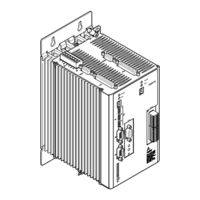
Festo CMMD-AS series Installation Manual (131 pages)
Motor controller
Brand:
Festo
| Category:
Controller
| Size: 6 MB
Table of Contents
Table of Contents
5
1 General Information
10
Documentation
10
Type Code CMMD-AS-C8-3A
10
Scope of Delivery
11
2 Safety Instructions for Electric Drives and Controllers
12
Icons Used
12
General Information
13
Hazards Due to Improper Use
14
Safety Instructions
15
General Safety Information
15
Safety Instructions for Assembly and Maintenance
17
Protection Aganst Touching Electric Components
18
Protection by Low Voltage (PELV) against Electric Shock
20
Protection against Dangerous Movements
20
Protection Aganst Touching Hot Components
21
Protection When Handling and Assembling
22
3 Product Description
23
General Information
23
Device Description
23
Bus Connection
24
Performance Characteristics
24
Interfaces
27
Overview of the Setpoint Value Interfaces
27
Analogue Setpoint Specification
28
Interfaces for Direct Synchronous Operation
28
I/O Functions and Device Control
34
RS232 Interface (Diagnosis/ Parametrisation Interface)
35
Control Via RS485
40
Multi-Firmware Strategy
42
Motor Feedback
42
Brake Chopper (Brake Control)
42
Feedback from Motor (Angle Encoder)
42
Control Interface [X1]
43
Increment Generator Interface [X10]
44
SD Card Holder [M1]
44
3.5.14 SD Memory Card
44
Field Bus Interface
45
FHPP (Festo Handling and Positioning Profile)
46
CAN Bus
47
Profibus
48
Devicenet
48
Function Overview
49
Operating Modes
49
Setpoint Value Processing
50
I²T Function
51
Positioning Controller
51
Homing
53
Trajectory Generator
57
I/O Sequence Control
58
Safety Functions, Error Messages
60
Behaviour When Switching off Enable
60
3.7.10 Oscilloscope Function
62
3.7.11 Jog and Teach Function I/O
63
Position Record Linking with Positioning/Torque Control Switching
68
3.7.13 On-The-Fly Measurement
74
3.7.14 Endless Positioning
74
3.7.15 Relative Positioning Records
76
3.7.16 Adjustment to the Axis and Motor Construction Set
76
4 Functional Safety Engineering
77
General Information and Intended Use
77
Integrated Function "Safe Torque Off" (STO)
80
General Remarks/Description "Safe Torque Off" (STO)
80
Timing Diagram, STO
81
Switching Example STO
83
EMERGENCY STOP Request, Monitoring of Protective Door
85
Testing the Safety Function STO
86
Integrated Function "Safe Stop 1" (SS1)
87
General Remarks/Description "Safe Stop 1" SS1
87
Timing Diagram, SS1
88
Activation of SS1
90
Setting the Switch-Off Delay
90
Parameterization Example FCT
91
Sample Circuit SS1
92
EMERGENCY STOP Request, Monitoring of Protective Door
94
Restoration of Normal Operation
95
Testing the Safety Function
95
4.3.10 Determination of the Brake Time
95
4.3.11 Setting the Delay Time
96
5 Mechanical Installation
97
Important Instructions
97
Mounting
98
6 Electrical Installation
100
Device View
100
Interfaces
102
Entire System CMMD-AS
103
Interfaces and Plug Assignments
105
I/O Interface [X1.1/2]
105
Shaft Encoder Motor - Endat 2.1 and 2.2 [X2.1/2]
108
Safe Stop [X3.1/2]
109
Field Bus CAN [X4]
109
Rs232/Rs485 [X5]
109
Motor Connection [X6.1/2]
110
Power Supply [X9]
110
Synchronisation Control [X10.1/2]
111
SD Card [M1]
111
6.4.10 Field Bus Settings and Boot Loader
112
Instructions on Safe and EMC-Compliant Installation
113
Explanations and Terms
113
Connection Instructions
113
General Information on EMC
113
EMC Areas: Second Environment
114
EMC-Compliant Wiring
114
Operation with Long Motor Cables
115
ESD Protection
115
7 Preparations for Commissioning
116
General Connection Instructions
116
Tools / Material
116
Connect the Motor to the Motor Controller
116
Connecting Motor Controller to the Power Supply
117
Connecting a PC
117
Checking Readiness for Operation
117
Timing Diagram Switch-On Sequence
118
8 Service Functions and Error Messages
119
Protective and Service Functions
119
Overview
119
Temperatur Monitoring for Motor and Power Section, Shaft Encoder Monitoring
119
Short-Circuit Monitoring of the Output Stage/Overload Current and Short-Circuit Monitoring
119
Voltage Monitoring for the Intermediate Circuit
120
I²T Monitoring
120
Temperature Monitoring for the Heat Sink
120
Power Monitoring for the Brake Chopper
120
Operating Mode and Error Messages
121
Operating Mode and Error Display
121
Error Messages
121
Technical Data
125
A.1 General
125
A.2 Operation and Display Components
126
Status Display
126
Control Elements
126
A.3 Interfaces
127
I/O Interface [X1.1/2]
127
Shaft Encoder Motor [X2.1/2]
128
CAN Bus [X4]
128
Rs232/Rs485 [X5]
128
Motor Connection [X6.1/2]
129
Power Supply [X9]
130
Increment Generator Interface [X10.1/2]
130
Index
131
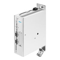
Festo CMMD-AS series Manual (20 pages)
CANopen for Motor Controller
Brand:
Festo
| Category:
Controller
| Size: 2 MB
Table of Contents
Table of Contents
5
General Remarks
8
Intended Use
8
Safety Instructions
8
Target Group
9
Service
9
Important User Instructions
9
Canopen
12
Overview
12
Cabling and Plug Assignment
13
Pin Allocations
13
Cabling Note
14
Activation of Canopen
15
Access Procedure
17
Introduction
17
SDO Access
18
SDO Sequences for Reading and Writing
19
SDO Error Messages
20
Advertisement
Advertisement
Related Products
Festo s CMMD-AS-C8-3A
Festo CMMD-AS
Festo CMMP-AS-C5-3A
Festo CMMS-ST Series
Festo CMMS-ST-*-G2 Series
Festo CMMO-ST
Festo CMMP-AS-C5-11A-P3-M3
Festo CMMP-AS-C10-11A-P3-M3
Festo CMMP-AS-C2-3A-M3-C1
Festo CMMP-AS-C5-3A-M3-C1
Festo Categories
Industrial Equipment
Control Unit
Controller
Touch terminals
DC Drives
More Festo Manuals
Login
Sign In
OR
Sign in with Facebook
Sign in with Google
Upload manual
Upload from disk
Upload from URL