Sign In
Upload
Manuals
Brands
Festo Manuals
Controller
CMMP-AS-C5-3A
User Manuals: Festo CMMP-AS-C5-3A AC Servo Drive
Manuals and User Guides for Festo CMMP-AS-C5-3A AC Servo Drive. We have
2
Festo CMMP-AS-C5-3A AC Servo Drive manuals available for free PDF download: Mounting And Installation Manual, Brief Overview
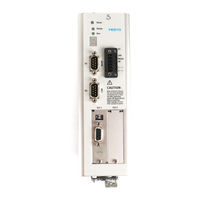
Festo CMMP-AS-C5-3A Mounting And Installation Manual (110 pages)
Type CMMP-AS-3A.... Motorcontroller CMMP...
Brand:
Festo
| Category:
Controller
| Size: 11 MB
Table of Contents
Table of Contents
5
1 General Data
10
Documentation
10
Scope of Delivery
11
2 Safety Instructions for Electric Drives and Controllers
12
Icons Used
12
General Information
12
Danger through Incorrect Use
14
Safety Instructions
15
General Safety Information
15
Safety Instructions for Assembly and Maintenance
16
Protection against Touching Electric Components
18
Protection by Low Voltage (PELV) against Electric Shock
20
Protection from Dangerous Movements
20
Protection against Touching Hot Components
21
Protection When Handling and Assembling
22
3 Product Description
23
General Data
23
Switch-On Sequence
26
Power Supply
27
Single-Phase AC Supply with Active PFC
27
Intermediate Circuit Coupling, DC Power Supply
29
Mains Fuse
29
Brake Chopper
29
Communication Interfaces
30
Festo Profile for Handling and Positioning (FHPP)
30
RS232 Interface
31
CAN Bus
31
Profibus
31
Devicenet
32
Sercos
32
I/O Functions and Device Control
33
4 Function Overview
35
Motors
35
Synchronous Servo Motors
35
Linear Motors
35
Functions of the CMMP-AS Servo Positioning Controller
35
Compatibility
35
Pulse Width Modulation (PWM)
36
Setpoint Management
36
Controlled Torque Mode
37
Controlled Speed Mode
37
Torque-Limited Speed Control
38
Synchronisation to External Clock Sources
38
Load Torque Compensation for Vertical Axes
38
Positioning and Position Control
38
4.2.10 Synchronisation, Electrical Gearboxes
40
4.2.11 Brake Management
40
Positioning Control
40
Overview
40
Relative Positioning
41
Absolute Positioning
42
Motion Profile Generator
42
Homing Run
42
Positioning Sequences
43
Optional Stop Input
44
Contour Control with Linear Interpolation
44
Time-Synchronised Multi-Axis Positioning
45
5 Functional Safety Engineering
46
General Information and Intended Use
46
Integrated "Safe Standstill" Function
48
General Information / Description of "Safe Standstill
48
Secure Stopping Brake Control
50
Functional Method / Timing
51
Typical Applications
54
6 Mechanical Installation
59
Important Instructions
59
Device View
61
Assembly
64
7 Electrical Installation
65
Connector Pin Assignments
65
Entire CMMP-AS System
66
Connection: Power Supply [X9]
68
Layout on Device [X9]
68
Counterplug [X9]
68
Pin Assignments [X9]
68
Calculating the Required Braking Resistor
69
Connection: Motor [X6]
69
Layout on Device [X6]
69
Counterplug [X6]
69
Pin Assignments [X6]
69
Connection: I/O Communication [X1]
70
Layout on Device [X1]
71
Counterplug [X1]
71
Pin Assignments [X1]
72
Type and Layout of Cable [X1]
72
Connection Notes [X1]
73
Connection: Safe Standstill [X3]
74
Layout on Device [X3]
75
Counterplug [X3]
75
Pin Assignments [X3]
75
Connection: Resolver [X2A]
75
Layout on Device [X2A]
75
Counterplug [X2A]
75
Pin Assignments [X2A]
75
Connection: Encoder [X2B]
76
Layout on Device [X2B]
76
Counterplug [X2B]
76
Connection: Increment Encoder Input [X10]
77
Layout on Device [X10]
77
Counterplug [X10]
77
Pin Assignments [X10]
77
Type and Layout of Cable [X10]
77
Connection Notes [X10]
77
Connection: Incremental Encoder Output [X11]
78
Layout on Device [X11]
78
Counterplug [X11]
78
Pin Assignments [X11]
78
Connection: CAN Bus [X4]
78
Layout on Device [X4]
78
Counterplug [X4]
79
Pin Assignments [X4]
79
Connection Notes [X4]
79
Connection: RS232/COM [X5]
80
Layout on Device [X5]
80
Counterplug [X5]
80
Pin Assignments [X5]
81
Instructions on Safe and EMC-Compliant Installation
82
7.13.1 Explanations and Terms
82
7.13.2 Connection Instructions
82
7.13.3 General Information on EMC
82
7.13.4 EMC Areas: First and Second Environments
83
7.13.5 EMC-Compliant Wiring
84
7.13.6 Operation with Long Motor Cables
84
7.13.7 ESD Protection
85
8 Startup
86
General Connection Instructions
86
Tools / Material
86
Connecting the Motor
86
Connect the CMMP-AS Servo Positioning Controller to the Power Supply
87
Connecting a PC
87
Checking Readiness for Operation
87
9 Service Functions and Error Messages
89
Protective and Service Functions
89
Overview
89
Overload Current and Short-Circuit Monitoring
89
Overvoltage Monitoring for the Intermediate Circuit
89
Temperature Monitoring for the Heat Sink
89
Motor Monitoring
90
I²T Monitoring
90
Power Monitoring for the Brake Chopper
90
L²T Monitoring of the PFC Stage
90
Commissioning Status
90
9.1.10 Operating Time Counter
91
Operating Mode and Error Messages
91
Operating Mode and Error Display
91
Error Messages
91
Acknowledge Error
100
Technical Specifications
101
Operation and Display Components
102
Power Supply [X9]
102
Motor Connection [X6]
104
Angle Encoder Connections [X2A] and [X2B]
104
Resolver Connection [X2A]
104
Encoder Connection [X2B]
105
Encoder Connection [X2B] for EMMS-AS
105
Communication Interfaces
106
Rs232 [X5]
106
CAN Bus [X4]
106
A.5 Communication Interfaces
106
I/O Interface [X1]
107
A.5.3 I/O Interface [X1]
107
Increment Encoder Input [X10]
108
Incremental Encoder Output [X11]
108
Glossary
109
Advertisement
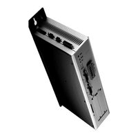
Festo CMMP-AS-C5-3A Brief Overview (86 pages)
Motor controller
Brand:
Festo
| Category:
Controller
| Size: 2 MB
Table of Contents
Table of Contents
2
Deutsch
3
English
17
Español
31
Français
45
Italiano
59
Svenska
73
Advertisement
Related Products
Festo CMMP-AS-C5-3A-M0
Festo CMMP-AS-C5-11A-P3-M0
Festo CMMP-AS-C5-3A-M3
Festo CMMP-AS-C5-11A-P3-M3
Festo CMMP-AS-C5-11A-P3-M0-C1
Festo CMMP-AS-C5-11A-P3-M3-C1
Festo CMMP-AS-C5-3A-M0-C1
Festo CMMP-AS-C5-3A-M3-C1
Festo CMMP-AS-C5-11A
Festo CMMP-AS-C10-11A-P3-M0
Festo Categories
Industrial Equipment
Control Unit
Controller
Touch terminals
DC Drives
More Festo Manuals
Login
Sign In
OR
Sign in with Facebook
Sign in with Google
Upload manual
Upload from disk
Upload from URL