Sign In
Upload
Manuals
Brands
FARGO electronics Manuals
Printer
DTC300M
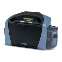
User Manuals: FARGO electronics DTC300M ID Card Printer
Manuals and User Guides for FARGO electronics DTC300M ID Card Printer. We have
2
FARGO electronics DTC300M ID Card Printer manuals available for free PDF download: Service Manual, User Manual
FARGO electronics DTC300M Service Manual (446 pages)
Card printer
Brand:
FARGO electronics
| Category:
Printer
| Size: 6 MB
Table of Contents
Table of Contents
3
Section 1: Introduction
9
How to Use the Manual
9
Safety Messages (Review Carefully)
10
DTC400/DTC300/DTC300M Card Printer Overview
11
Reviewing the DTC400/DTC300/DTC300M Block Diagram
11
Reviewing the DTC400/DTC300/DTC300M Sequence of Operations
12
Step Process
14
Reviewing the DTC400/DTC300/DTC300M Boot up Sequence
15
Section 2: Specifications
16
Table of Contents
16
Regulatory Compliances
17
Agency Listings
18
Technical Specifications
18
Technical Specifications (Continued)
18
Technical Specifications (Continued)
19
Visual Security Solutions (Specifications)
21
Verimarktm Cards - 2-D Holographic Foil Application
21
Custom Holomarktm Cards
21
Visual Security - Card Stock Part Numbers
21
Visual Security - Fargo Certified Overlaminates (Special Order in 50 Quantity Minimum)
21
Visual Security Card Stock - Tolerances
21
Verimarktm - Application Specifications
22
Holomarktm and Custom Holomarktm - Application Specifications
22
Functional Specifications
23
Printer Components: Front Cover to USB Port
24
Printer Components: Print Ribbons
25
Printer Components: Resin-Only Print Ribbons
26
Printer Components: Dye-Sublimation Print Ribbons
27
Printer Components: Dye-Sublimation/Resin Print Ribbons
28
Printer Components: Blank Cards
29
Printer Module: Flipper Table Module Assembly (D900200)
30
Section 3: Secure Print Security Suite
31
Overview
31
Password Control Application
31
Print Diagnostics Application
31
Print Notification Application
31
Security Imaging Application
31
Supplies E-Ordering Application
31
Print Security Suite - Main Window
32
Securemark Media
32
Section 4: Setup and Installation Procedures
33
Table of Contents
33
Printer Setup and Installation
35
Choosing a Good Location
35
About Moisture Condensation
35
Unpacking and Inspection
36
Reviewing the Printer (Front View)
36
Reviewing the Printer (Front View; Cartridge Being Installed)
37
Reviewing the LCD (Top-Front Part of Printer)
37
Connecting the Printer Power
38
Installing the Print Ribbon Cartridge
39
Installing the Print Ribbon Cartridge (Continued)
40
Installing Blank Cards into the Card Hopper
42
Installing Blank Cards into the Card Hopper (Continued)
43
Lowering the Card Output Hopper
45
Flipper Table Module Installation
46
Installing the Flipper Table Module Assembly (D900200)
46
Installing the Flipper Table Module Assembly (D900200) (Continued)
47
DTC400 Card Printer/Encoder Card Flipper Module Upgrade Kit
49
Introduction
49
Installing the Card Flipper Module Upgrade Kit
50
Installing the Card Flipper Module Upgrade Kit (Continued)
51
Installing the Card Flipper Module Upgrade Kit (Continued)
53
Installing the Card Flipper Module Upgrade Kit (Continued)
54
Installing the Card Flipper Module Upgrade Kit (Continued)
55
Installing the Card Flipper Module Upgrade Kit (Continued)
56
Installing the Card Flipper Module Upgrade Kit (Continued)
57
Printer Driver Installation
58
Installing the Printer Driver
58
Installing the Printer Driver (Continued)
59
Installing the Printer Driver (Continued)
61
Installing the Printer Driver (Continued)
62
Installing the Printer Driver (Continued)
63
Installing the Printer Driver (Continued)
64
Installing the Printer Driver (Continued)
65
Installing the Printer Driver (Continued)
66
Installing the Printer Driver (Continued)
67
Installing the Printer Driver (Continued)
68
Installing the Printer Driver (Continued)
69
Installing the Printer Driver (Continued)
70
Printing a Test Print Image
71
Printing a Test Print Image (Continued)
72
Printer Transport
73
Moving the Printer to Another Location
73
Section 5: General Troubleshooting
74
Table of Contents
74
Safety Messages (Review Carefully)
76
Communications Errors
77
Resolving the Communication Errors
77
Resolving the Communication Errors (Continued)
78
Print Process Errors
79
Resolving a Card Not Fed Error (Cards will Not Feed off the Hopper)
79
Resolving a Card Not Fed Error (Cards will Not Feed off the Hopper) (Continued)
80
Resolving a Card Not Fed Error (Two (2) or more Card Feed at the same Time)
82
Resolving a Card Not Fed Error (Two (2) or more Card Feed at the same Time) (Continued)
83
Resolving a Ribbon RFID Error (Ribbon RFID Antenna Is Corrupted)
84
Resolving a Ribbon RFID Error (Ribbon RFID Antenna Is Corrupted) (Continued)
85
Resolving a Ribbon RFID Error (Ribbon RFID Sensor Is Corrupted)
86
Resolving the Mag Verify Error
87
Resolving the Mag Verify Error (Continued)
88
Resolving the no Mag Installed Error
90
Resolving the no Mag Installed Error (Continued)
91
Resolving a Ribbon Sensor Error (Ribbon Miscue)
92
Resolving a Ribbon Sensor Error (Ribbon Miscue) (Continued)
93
Resolving a Ribbon Break Jam Error
94
Resolving a Ribbon Break Jam Error (Continued)
95
Resolving a Ribbon out Error
96
Resolving a no Ribbon Installed Error
97
Resolving a no Ribbon Installed Error (Continued)
98
Resolving a Invalid Ribbon Error
99
Resolving a Invalid Ribbon Error (Continued)
100
Resolving a Wrong Ribbon Error
101
Resolving a Wrong Ribbon Error (Continued)
102
Resolving a Card Jam Error
103
Resolving a Card Jam Error (Continued)
104
Resolving a Headlift Motor or Sensor Error
105
Resolving the Cover Open Error Message
106
Resolving a Headlift Motor or Sensor Error (Continued)
106
Resolving the Blank Output Issues
108
Resolving the Blank Output Issues (Continued)
109
Flipper Table Module Assembly Problems
111
Resolving the no Flipper Table Module Problem
111
Resolving the Flipper Jam Error
112
Resolving the Blank Output Issues (Continued)
113
Diagnosing Image Problems
114
Resolving the Pixel Failure Problems
114
Resolving the Card Surface Debris Problems
115
Resolving the Incorrect Image Darkness Problems
116
Resolving the Incorrect Image Darkness Problems (Continued)
117
Resolving Ribbon Wrinkle Problems
118
Resolving Ribbon Wrinkle Problems (Continued)
119
Resolving the Excessive Resin Printing Problems
120
Resolving the Excessive Resin Printing Problems (Continued)
121
Resolving the Incomplete Resin Printing Problems
122
Resolving the Image Placement Problems
123
Resolving the Image Placement Problems (Continued)
123
Resolving the Poor Image Quality Problems
126
Running the Self Test
127
Running the Standard Self Test Print
128
Running the Magnetic Self Test (Hico Only)
129
Section 6: Printer Adjustments
130
Table of Contents
130
Safety Messages (Review Carefully)
133
Safety Messages (Review Carefully)
134
DTC400/DTC300 Print Driver Options
135
Reviewing DTC400, DTC300 and DTC300M Printer Drivers
135
Reviewing DTC400 Printer Drivers
135
Reviewing DTC300 Printer Driver
136
Reviewing DTC300M Printer Drivers
137
Using the Card Tab (DTC400/DTC300/DTC300M)
138
Adjusting the Card Size Option
138
Adjusting the Orientation Option
139
Selecting the Number of Copies
140
Using the Diagnostics Button under the Card Tab
141
Using the Clean Printer Option
142
Using the Clean Printer Option (Continued)
143
Using the Test Print Button
144
Using the about Button
145
Using the Device Options Tab (DTC400/DTC300)
146
Reviewing the Device Options Tab (DTC400)
146
Reviewing the Device Options Tab (DTC300)
147
Adjusting the Ribbon Type Option
148
Selecting the Auto Ribbon Select Option
149
Adjusting the Color Matching Option
150
Adjusting for the Resin Dither
151
Using the Print both Sides Option
152
Using the Split 1 Set of Ribbon Panels Option
153
Using the Print Back Side First Option
154
Using the Print Back Side Only Option
155
Using the Rotate Front 180 Degrees or Rotate Back 180 Degrees Options
156
Using the Disable Printing Option
157
Using the Device Options Tab (DTC300M)
158
Reviewing the Device Options Tab (DTC300M)
158
Adjusting the Ribbon Type Option (DTC300M)
159
Selecting the Auto Ribbon Select Option (DTC300M)
160
Adjusting for the Resin Dither (DTC300M)
161
Using the Resin Heat, Front (K) Option (DTC300M)
162
Using the Resin Heat, Back (K) Option (DTC300M)
163
Using the Overlay Heat (O) Option (DTC300M)
164
Using the Print both Sides Option (DTC300M)
165
Using the Print Back Side First Option
166
Using the Print Back Side Only Option
167
Using the Rotate Front 180 Degrees or Rotate Back 180 Degrees Options
168
Using the Disable Printing Option
169
Using the Image Color Tab (DTC400/DTC300)
170
Using the Resin Heat (K) Option (Front and Back)
171
Using the Overlay Heat (O) Option
172
Using the Color Matching Option and Default Button
173
Using the Calibrate Tab (DTC400/DTC300/DTC300M)
174
Using the Image Position Controls
175
Using the Image Position Controls (Continued)
176
Using the Sensors Button
177
Using the Settings Button
178
Using the Magnetic Encoding Tab (DTC400/DTC300/DTC300M)
179
Using the Magnetic Track Selection Radio Buttons
180
Using the Magnetic Track Selection Radio Buttons (Continued)
181
Using the Magnetic Track Options Radio Buttons
182
Using the Bit Density Radio Buttons
183
Using the Character Size Radio Buttons
184
Reviewing the Enable MLE Support Checkbox
185
Using the ASCII Offset Radio Buttons
186
Using the LRC Generation Radio Buttons
187
Using the Character Parity Radio Buttons
187
Using the Shift Data Left Checkbox
188
Reviewing the ISO Track Locations
189
Sending the Track Information
190
Entering the Track Information
190
Reviewing Tracks 1, 2 and 3 (in Table Format)
191
Reviewing the Track Data Note
191
Reviewing the ASCII Code and Character Table
192
Using the Overlay / Print Area Tab (DTC400/DTC300/DTC300M)
193
Enabling the Frontside and Backside Options
194
Enabling the Frontside Option (Overlay / Print Area)
195
Enabling the Backside Option (Overlay / Print Area)
196
Using the Overlay / Print Area Dropdown Menu
197
Using the Overlay / Print Area Dropdown Menu (Continued)
198
Using the Overlay / Print Area
199
Using the Overlay / Print Area (Continued)
200
Using the Defined Area Option
201
Using the Defined Area Option (Continued)
202
Using the Defined Area Option (Continued)
204
Using the Defined Area Option (Continued)
205
Using Security Options (Visual Security Solutions) (Frontside Option Only)
206
Selecting Orientation - Landscape under Card Tab
207
Selecting the Visual Security Solutions Dropdown Menu (a to D)
208
Selecting Orientation - Portrait under Card Tab
209
Selecting the Visual Security Solutions Dropdown Menu (E to H)
210
Selecting the Verimark Radio Button (Frontside Option Only)
211
Selecting the Holomark Radio Button (Frontside Option Only)
212
Reviewing the Custom Verimark Card (Custom Graphic in a 2D Foil)
213
Sample 1: Verimark Card (Landscape - Orientation) - 4 Positions (Below)
213
Sample 2: Verimark Card (Portrait - Orientation) - 4 Positions (Below)
213
Reviewing the Custom Holomark Card (Custom Graphic in a 2D Foil)
214
Sample 1: Holomark Card (Landscape - Orientation) - 4 Positions (Below)
214
Sample 2: Holomark Card (Portrait - Orientation) - 4 Positions (Below)
214
Using the K Panel Resin Tab (DTC400/DTC300)
215
Enabling the Frontside and Backside Options
216
Enabling the Frontside Option (K Panel Resin)
217
Enabling the Backside Option (K Panel Resin)
218
Selecting from the Print All Black with K Panel Options (Front and Back Options)
219
Selecting the Full Card Option (Front and Back Options)
220
Selecting the Defined Area(S) Option (Front and Back Options)
221
Selecting the Undefined Area(S) Option (Front and Back Options)
222
Selecting the Defined Area(S) Function (Front and Back Options)
223
Selecting the Defined Area(S) Function (Continued)
224
Selecting the Defined Area(S) Function (Continued)
226
Selecting the Defined Area(S) Function (Continued)
227
Selecting the Defined Area(S) Function (Continued)
228
Selecting the Defined Area(S) Function (Continued)
229
Selecting the Print YMC under K and Print K Only Options
230
Using the Printer Supplies Tab (DTC400/DTC300/DTC300M)
231
Reviewing the Ribbon Information
232
Reviewing the Ribbon Level Indicator
233
Using the Printer Calibration Utility (DTC400/DTC300/DTC300M)
234
Using the Image Darkness Option
235
Using the Print Top of Form Option
236
Card Output
237
Using the Print End of Form Option
237
Using the Print Left of Form Option
238
Using the Magnetic Encoder Voltage Offset Option
239
Adjusting the Hi-Co Voltage Offset
240
Adjusting the Lo-Co Voltage Offset
241
Using the Mag Top of Form Option
242
Using the Mag Top of Form Option (Continued)
243
Using the Ribbon Tension Option
244
Using the LCD Contrast Option
244
Using the Flipper Home Offset Option
245
Using the Flipper Center Offset Option
245
Using the Flipper Smart Angle Offset Option
246
Section 7: Cleaning
247
Table of Contents
247
Section 7: Cleaning________________________________________________________ 7-1
248
Safety Messages (Review Carefully)
248
DTC400/DTC300/DTC300M Card Printer/Encoders Cleaning Kit (Part Number 085976)
249
Supplies (Included with the Cleaning Kit)
249
Cleaning the Printhead
250
Cleaning the Platen and the Card Feed Rollers
251
Cleaning the Platen and the Card Feed Rollers (Continued)
252
Cleaning the Platen and the Card Feed Rollers (Continued)
253
Cleaning the Printer's Interior
254
Cleaning the Printer's Exterior
254
Section 8: Parts Replacement
255
Table of Contents
255
Safety Messages (Review Carefully)
258
Reviewing DTC400/DTC300/DTC300M Parts Replacement Table
259
Reviewing DTC400/DTC300/DTC300M Parts Replacement Table (Continued)
260
Reviewing DTC400/DTC300/DTC300M Parts Replacement Table (Continued)
262
Reviewing DTC400/DTC300/DTC300M Parts Replacement Table (Continued)
264
Reviewing DTC400/DTC300/DTC300M Parts Replacement Table (Continued)
265
Reviewing DTC400/DTC300/DTC300M Parts Replacement Table (Continued)
266
Reviewing DTC400/DTC300/DTC300M Parts Replacement Table (Continued)
267
Reviewing DTC400/DTC300/DTC300M Parts Replacement Table (Continued)
268
Reviewing DTC400/DTC300/DTC300M Parts Replacement Table (Continued)
269
Reviewing DTC400/DTC300/DTC300M Parts Replacement Table (Continued)
270
Reviewing DTC400/DTC300/DTC300M Parts Replacement Table (Continued)
271
Reviewing DTC400/DTC300/DTC300M Parts Replacement Table (Continued)
272
Reviewing DTC400/DTC300/DTC300M Parts Replacement Table (Continued)
273
Reviewing DTC400/DTC300/DTC300M Parts Replacement Table (Continued)
274
Reviewing DTC400/DTC300/DTC300M Parts Replacement Table (Continued)
275
Reviewing the Main Print Board Connections
276
Reviewing the Power/Usb Board Connections
276
Cover, Door and Tray Removal
277
Replacing the Rear Cover (D900066)
277
Replacing the Rear Cover (D900066) (Continued)
278
Replacing the Left End Cap (D900064)
279
Replacing the Left End Cap (D900092)
280
Replacing the Right End Cap (D900065-01 and -02)
282
Replacing the Right End Cap (D900065-01 and -02) (Continued)
283
Replacing the Input Door Assembly (D900148)
284
Replacing the Output Door Assembly (D900092)
285
Replacing the Output Door Assembly (D900092) (Continued)
286
Replacing the Input Tray (D900097)
287
Replacing the Input Tray (D900097) (Continued)
288
Replacing the Printhead Access Cover (D900029)
289
Replacing the Printhead Access Cover (D900029) (Continued)
290
Replacing the Magnetic Module Door (D900107)
291
Replacing the Magnetic Module Door (D900107) (Continued)
292
Replacing the Top Cover Assembly (Includes Print Circuit Board)
293
Replacing the Top Cover Assembly (Includes Print Circuit Board) (Continued)
294
Replacing the Front Cover (D900072-03 DTC300M, D900072-02 DTC300, D900072-01 DTC400) (Continued)
297
Plate Removal
298
Replacing the Baseplate (D900000)
298
Replacing the Baseplate (D900000) (Continued)
299
Replacing the Baseplate (D900000) (Continued)
301
Replacing the Baseplate (D900000) (Continued)
302
Replacing the Baseplate (D900000) (Continued)
303
Replacing the Clean Roller Plate (D900102)
304
Replacing the Clean Roller Plate (D900102) (Continued)
305
Replacing the Ribbon Motor Supply Assembly (D900121), O-Ring Drive Belt (140212), Encoder (A000126) Sensor and Motor (D840980)
307
Replacing the Ribbon Motor Supply Assembly (D900121), O-Ring Drive Belt (140212), Encoder (A000126) Sensor and Motor (D840980) (Continued)
308
Replacing the Ribbon Motor Supply Assembly (D900121), O-Ring Drive Belt (140212), Encoder (A000126) Sensor and Motor (D840980) (Continued)
309
Replacing the Ribbon Motor Supply Assembly (D900121), O-Ring Drive Belt (140212), Encoder (A000126) Sensor and Motor (D840980) (Continued)
310
Board, Interface and Printhead Replacements
311
Replacing the Power/Communication Board (A000368)
311
Replacing the Power/Communication Board (A000368) (Continued)
312
Replacing the Printhead Assembly (D900023)
313
Replacing the Printhead Assembly (D900023) (Continued)
314
Motor and Magnetic Head Replacements
316
Replacing the Headlift Motor Assembly (D900085)
317
Replacing the Headlift Motor Assembly (E000806) and the Headlift Cam (D900075) (Continued)
318
Replacing the Headlift Motor Assembly (E000806) and the Headlift Cam (D900075) (Continued)
320
Replacing the Input Feed Motor Assembly (D900084)
321
Replacing the Input Feed Motor Assembly (D900084) (Continued)
322
Replacing the Stepper Motor Assembly (D900087)
324
Replacing the Stepper Motor Assembly (D900087) (Continued)
325
Replacing the Ribbon Take-Up Motor (D900086)
326
Replacing the Ribbon Take-Up Motor (D900086) (Continued)
327
Replacing the Magnetic Head Assembly (D900050)
329
Replacing the Magnetic Module Door (D900107) (Continued)
330
Sensor Replacement
331
Replacing the Ribbon LED Sensor Assembly (A000374 and D900138)
331
Replacing the Ribbon LED Sensor Assembly (A000374 and D900138) (Continued)
332
Replacing the RFID Sensor Assembly (A000365), Ribbon Encoder Wheel (810492), Encoder Pulley (D900106) and Ribbon Supply Hub (D900090)
333
Replacing the RFID Sensor Assembly (A000365), Ribbon Encoder Wheel (810492), Encoder Pulley (D900106) and Ribbon Supply Hub (D900090) (Continued)
334
Replacing the RFID Sensor Assembly (A000365), Ribbon Encoder Wheel (810492), Encoder Pulley (D900106) and Ribbon Supply Hub (D900090) (Continued)
335
Replacing the RFID Sensor Assembly (A000365), Ribbon Encoder Wheel (810492), Encoder Pulley (D900106) and Ribbon Supply Hub (D900090) (Continued)
336
Replacing the Headlift Sensor Assembly (D900113)
337
Replacing the Headlift Sensor Assembly (D900113) (Continued)
338
Roller, Cable and Fan Replacement
339
Refer to Drawing D900110
339
Replacing the Platen Roller (D900041)
339
Replacing the Platen Roller (D900041) (Continued)
341
Replacing the Card Cleaning or Feed Roller (D900040) (Left of Platen) and the Card Drive Gear (810266)
343
Replacing the Card Cleaning or Feed Roller (D900040) (Left of Platen) and the Card Drive Gear (810266) (Continued)
343
Replacing the Card Cleaning or Feed Roller (D900040) (Left of Platen) and the Card Drive Gear (810266) (Continued)
344
Replacing the Input Pusher (D900104)
345
Replacing the Input Pusher (D900104) (Continued)
346
Refer to Drawing D900110
347
Replacing the Card Feed or Exit Roller (D900042) and the Card Drive Gear (810266)
348
Replacing the Card Feed or Exit Roller (D900042) and the Card Drive Gear (810266) (Continued)
348
Refer to Drawing D900110
350
Replacing the Pinch Roller (D900098)
350
Replacing the Pinch Roller (D900098) (Continued)
351
Replacing the Cleaning Roller Lever (D900051)
353
Replacing the Cleaning Roller Lever (D900051) (Continued)
354
Replacing the Printhead Cable Assembly (D900035)
356
Replacing the Printhead Cable Assembly (D900035) (Continued)
357
Replacing the Fan Assembly (D900033)
358
Replacing the Fan Assembly (D900033) (Continued)
359
Pulley Removal
360
Replacing the Stepper Motor Idler Pulley (D840888) and the Platen Roller Drive Gear (D900047)
360
Replacing the Stepper Motor Idler Pulley (D840888) and the Platen Roller Drive Gear (D900047) (Continued)
361
Replacing the Stepper Motor Idler Pulley Shaft Assembly (D900089) and the Stepper Motor Drive Belt (F000094)
362
Replacing the Stepper Motor Idler Pulley Shaft Assembly (D900089) and the Stepper Motor Drive Belt (F000094) (Continued)
363
Flipper Table Replacement
364
Replacing the Flipper Table Module Assembly (D900200)
364
Replacing the Flipper Table Module Assembly (D900200) (Continued)
365
Section 9: Packing the Card Printer
367
Section 10: Board Level Diagnostics
368
Safety Messages (Review Carefully)
368
Sensor and Motor
369
Reviewing the Motor Voltages (When Active)
369
Reviewing the Sensor Location and Voltages
369
Section 11: Diagnostic Tool Utility
370
Section 11: Diagnostic Tool Utility___________________________________________ 11-1
371
Using the Diagnostic Tool Utility
371
Selecting from the Printer Selection Menu
371
Reviewing Customized Diagnostic Utility Tabs for Your Printer
372
Using the Diagnostic Utility Tabs
373
Selecting the Print Spooler Tab in the Diagnostics Utility
373
Selecting the Print Spooler Tab in the Diagnostics Utility (Continued)
374
Selecting the Print Spooler Tab in the Diagnostics Utility (Continued)
376
Selecting the Print Spooler Tab in the Diagnostics Utility (Continued)
377
Selecting the Firmware Updates Tab in the Diagnostics Utility
378
Downloading Firmware Updates
379
Selecting the Firmware File
379
Placing the Printer in the Upgrade Mode
380
Sending the Firmware File
381
Selecting the Mechanics Tab in the Diagnostics Utility
382
Selecting the Mechanics Tab in the Diagnostics Utility (Continued)
383
Selecting the Mechanics Tab in the Diagnostics Utility (Continued)
385
Selecting the Mechanics Tab in the Diagnostics Utility (Continued)
386
Selecting the Mechanics Tab in the Diagnostics Utility (Continued)
387
Selecting the Mechanics Tab in the Diagnostics Utility (Continued)
388
Selecting the Mechanics Tab in the Diagnostics Utility (Continued)
389
Selecting the Mechanics Tab in the Diagnostics Utility (Continued)
390
Selecting the Mechanics Tab in the Diagnostics Utility (Continued)
391
Selecting the Mechanics Tab in the Diagnostics Utility (Continued)
392
Selecting the Self Tests Tab in the Diagnostics Utility
393
Selecting the Card Samples Tab in the Diagnostics Utility
394
Selecting the Magnetic Encoding Tab in the Diagnostics Utility
395
Selecting the Help Button in the Diagnostics Utility
396
Selecting the about Button in the Diagnostics Utility
397
Selecting the Exit Button in the Diagnostics Utility
398
Section 12: Firmware Upgrades
399
Introduction
399
Requirements
399
Table of Contents
399
Section 12: Firmware Upgrades _____________________________________________ 12-1
400
Safety Messages (Review Carefully)
400
Downloading Firmware
401
Downloading Firmware (Continued)
402
Downloading Firmware (Continued)
404
Downloading Firmware (Continued)
405
Downloading Firmware (Continued)
406
Downloading Firmware (Continued)
407
Downloading Firmware (Continued)
408
Downloading Firmware (Continued)
409
Downloading Firmware (Continued)
410
Downloading Firmware (Continued)
411
Downloading Firmware (Continued)
412
Downloading Firmware (Continued)
413
Downloading Firmware (Continued)
414
Placing the Printer in the Firmware Upgrade Mode
415
Placing the Printer in the Firmware Upgrade Mode (Continued)
416
Sending the Firmware File
417
Sending the Firmware File
418
Sending the Firmware File (Continued)
418
Section 13: Fargo Technical Support
419
Contacting Fargo Technical Support
419
Reading the Serial Numbers on a Fargo Printer
420
Finding out When a Fargo Card Printer was Manufactured
420
Reviewing Example No. 1: Serial Number 80453289
420
Reviewing Example No. 2: Serial Number A1280224
420
Section 14: Reviewing the Spare Parts List
421
Reviewing the DTC400/DTC300/DTC300M Spare Parts List
421
Section 15: Glossary of Terms
422
Section 16: Index
442
Advertisement
FARGO electronics DTC300M User Manual (278 pages)
FARGO electronic Printer User Manual
Brand:
FARGO electronics
| Category:
Printer
| Size: 5 MB
Table of Contents
Table of Contents
3
Section 1: Introduction
8
How to Use the Manual
8
Safety Messages (Review Carefully)
9
DTC400/DTC300/DTC300M Card Printer Overview
10
Reviewing the DTC400/DTC300/DTC300M Block Diagram
10
Reviewing the DTC400/DTC300/DTC300M Sequence of Operations
11
Step Process
11
Reviewing the DTC400/DTC300/DTC300M Boot up Sequence
14
Section 2: Specifications
15
Table of Contents
15
Regulatory Compliances
16
Agency Listings
17
Technical Specifications
17
Technical Specifications (Continued)
18
Visual Security Solutions (Specifications)
20
Verimarktm Cards - 2-D Holographic Foil Application
20
Custom Holomarktm Cards
20
Visual Security - Card Stock Part Numbers
20
Visual Security - Fargo Certified Overlaminates (Special Order in 50 Quantity Minimum)
20
Visual Security Card Stock - Tolerances
20
Verimarktm - Application Specifications
21
Holomarktm and Custom Holomarktm - Application Specifications
21
Functional Specifications
22
Printer Components: Front Cover
23
Printer Components: Print Ribbons
24
Printer Components: Resin-Only Print Ribbons
25
Printer Components: Dye-Sublimation Print Ribbons
26
Printer Components: Dye-Sublimation/Resin Print Ribbons
27
Printer Components: Blank Cards
28
Section 3: Setup and Installation Procedures
29
Table of Contents
29
Printer Setup and Installation
31
Choosing a Good Location
31
About Moisture Condensation
31
Unpacking and Inspection
32
Reviewing the Printer (Front View)
33
Reviewing the Printer (Front View; Cartridge Being Installed)
33
Reviewing the LCD (Top-Front Part of Printer)
34
Connecting the Printer Power
35
Installing the Print Ribbon Cartridge
36
Installing Blank Cards into the Card Hopper
39
Lowering the Card Output Hopper
42
Printer Driver Installation
43
Installing the Printer Driver
43
Printing a Test Print Image
55
Printing a Test Print Image (Continued)
56
Printer Transport
57
Moving the Printer to Another Location
57
Section 4: General Troubleshooting
58
Diagnosing Image Problems/Running the Self Test
59
Safety Messages (Review Carefully)
60
Communications Errors
61
Resolving the Communication Errors
61
Resolving the Communication Errors (Continued)
62
Print Process Errors
63
Resolving a Card Not Fed Error (Cards will Not Feed off the Hopper)
63
Resolving a Card Not Fed Error (Two (2) or more Card Feed at the same Time)
66
Resolving a Ribbon RFID Error (Ribbon RFID Antenna Is Corrupted)
68
Resolving a Ribbon RFID Error (Ribbon RFID Sensor Is Corrupted)
70
Resolving the Mag Verify Error
71
Resolving a Mag Verify Error (Continued)
72
Resolving the no Mag Installed Error
74
Resolving a Ribbon Sensor Error (Ribbon Miscue)
76
Resolving a Ribbon Sensor Error (Ribbon Miscue) (Continued)
77
Resolving a Ribbon Break Jam Error
78
Resolving a Ribbon Break Jam Error (Continued)
79
Resolving a Ribbon out Error
80
Resolving a no Ribbon Installed Error
81
Resolving a no Ribbon Installed Error (Continued)
82
Resolving a Invalid Ribbon Error
83
Resolving a Invalid Ribbon Error (Continued)
84
Resolving a Wrong Ribbon Error
85
Resolving a Wrong Ribbon Error (Continued)
86
Resolving a Card Jam Error
87
Resolving a Card Jam Error (Continued)
88
Resolving a Headlift Motor or Sensor Error
89
Resolving a Headlift Motor or Sensor Error (Continued)
90
Resolving the Cover Open Error Message
91
Resolving the Blank Output Issues
92
Resolving the Blank Output Issues (Continued)
93
Diagnosing Image Problems
95
Resolving the Pixel Failure Problems
95
Resolving the Card Surface Debris Problems
96
Resolving the Incorrect Image Darkness Problems
97
Resolving the Incorrect Image Darkness Problems (Continued)
98
Resolving Ribbon Wrinkle Problems
99
Resolving Ribbon Wrinkle Problems (Continued)
100
Resolving the Excessive Resin Printing Problems
101
Resolving the Excessive Resin Printing Problems (Continued)
102
Resolving the Incomplete Resin Printing Problems
103
Resolving the Image Placement Problems
104
Resolving the Image Placement Problems (Continued)
105
Resolving the Poor Image Quality Problems
107
Running the Self Test
108
Running the Standard Self Test Print
109
Running the Magnetic Self Test (Hico Only)
110
Section 5: Printer Adjustments
111
Table of Contents
111
Safety Messages (Review Carefully)
114
DTC400/DTC300 Print Driver Options
115
Reviewing DTC400 Printer Drivers
115
Reviewing DTC400, DTC300 and DTC300M Printer Drivers
115
Reviewing DTC300 Printer Driver
116
Reviewing DTC300M Printer Drivers
117
Using the Card Tab
118
Adjusting the Card Size Option
118
Adjusting the Orientation Option
119
Selecting the Number of Copies
120
Using the Diagnostics Button under the Card Tab
121
Using the Clean Printer Option
122
Using the Clean Printer Option (Continued)
123
Using the Test Print Button
124
Using the about Button
125
Using the Device Options Tab (DTC400/DTC300)
126
Adjusting the Ribbon Type Option
126
Selecting the Auto Ribbon Select Option
127
Adjusting the Color Matching Option
128
Adjusting for the Resin Dither
129
Using the Rotate Image 180 Degrees Option
130
Using the Disable Printing Option
131
Using the Device Options Tab (DTC300M)
132
Adjusting the Ribbon Type Option
132
Selecting the Auto Ribbon Select Option
133
Adjusting for the Resin Dither
134
Using the Rotate Image 180 Degrees Option
135
Using the Disable Printing Option
136
Using the Resin Heat (K) Option
137
Using the Overlay Heat (O) Option
138
Using the Image Color Tab (DTC400/DTC300)
139
Using the Resin Heat (K) Option
140
Using the Overlay Heat (O) Option
141
Using the Color Matching Option and Default Button
142
Using the Calibrate Tab
143
Using the Image Position Controls
144
Using Image Position Controls (Continued)
145
Using the Sensors Button
146
Using the Settings Button
147
Using the Magnetic Encoding Tab
148
Using the Magnetic Track Selection Radio Buttons
149
Using the Magnetic Track Selection Radio Buttons (Continued)
150
Using the Magnetic Track Options Radio Buttons
151
Using the Bit Density Radio Buttons
152
Using the Character Size Radio Buttons
153
Reviewing the Enable MLE Support Checkbox
154
Using the ASCII Offset Radio Buttons
155
Using the Character Parity Radio Buttons
156
Using the LRC Generation Radio Buttons
156
Using the Shift Data Left Checkbox
157
Reviewing the ISO Track Locations
158
Entering the Track Information
159
Sending the Track Information
159
Reviewing the Track Data Note
160
Reviewing Tracks 1, 2 and 3 (in Table Format)
160
Reviewing the ASCII Code and Character Table
161
Using the Overlay / Print Area Tab
162
Using the Overlay / Print Area Dropdown Menu
163
Using the Overlay / Print Area Dropdown Menu (Continued)
164
Using the Overlay / Print Area
165
Using the Overlay / Print Area (Continued)
166
Using the Defined Area Option
167
Using the Defined Area Option (Continued)
168
Using the Defined Area Option (Continued)
170
Using the Defined Area Option (Continued)
171
Using Security Options (Visual Security Solutions)
172
Selecting Orientation - Landscape under Card Tab
173
Selecting the Visual Security Solutions Dropdown Menu (a to D)
174
Selecting Orientation - Portrait under Card Tab
175
Selecting the Visual Security Solutions Dropdown Menu (E to H)
176
Selecting the Verimark Radio Button
177
Selecting the Holomark Radio Button
178
Reviewing the Custom Verimark Card (Custom Graphic in a 2D Foil)
179
Sample 1: Verimark Card (Landscape - Orientation) - 4 Positions (Below)
179
Sample 2: Verimark Card (Portrait - Orientation) - 4 Positions (Below)
179
Reviewing the Custom Holomark Card (Custom Graphic in a 2D Foil)
180
Sample 1: Holomark Card (Landscape - Orientation) - 4 Positions (Below)
180
Sample 2: Holomark Card (Portrait - Orientation) - 4 Positions (Below)
180
Using the K Panel Resin Tab
181
Selecting from the Print All Black with K Panel Options
182
Selecting the Full Card Option
183
Selecting the Defined Area(S) Option
184
Selecting the Undefined Area(S) Option
185
Selecting the Defined Area(S) Function
186
Selecting the Defined Area(S) Function (Continued)
187
Selecting the Defined Area(S) Function (Continued)
189
Selecting the Defined Area(S) Function (Continued)
190
Selecting the Defined Area(S) Function (Continued)
191
Selecting the Defined Area(S) Function (Continued)
192
Selecting the Print YMC under K and Print K Only Options
193
Using the Printer Supplies Tab
194
Reviewing the Ribbon Information
195
Reviewing the Ribbon Level Indicator
196
Using the Printer Calibration Utility
197
Using the Image Darkness Option
198
Using the Print Top of Form Option
199
Card Input
200
Card Output
200
Using the Print End of Form Option
200
Using the Print Left of Form Option
201
Using the Magnetic Encoder Voltage Offset Option
202
Adjusting the Hi-Co Voltage Offset
203
Adjusting the Lo-Co Voltage Offset
204
Using the Mag Top of Form Option
205
Using the Mag Top of Form Option (Continued)
206
Using the LCD Contrast Option
207
Using the Ribbon Tension Option
207
Table of Contents ______________________________________________________
208
Section 6: Cleaning
208
Safety Messages (Review Carefully)
209
Using the Required Supplies
210
Cleaning Procedures
211
Cleaning the Printhead
211
Cleaning the Card Feed and Cleaning Rollers
212
Cleaning the Printer's Exterior
213
Cleaning the Printer's Interior
213
Section 7: Parts Replacement
214
Section 8: Packing the Card Printer
215
Table of Contents
215
Section 9: Board Level Diagnostics
216
Table of Contents
216
Safety Messages (Review Carefully)
217
Reviewing the Motor Voltages (When Active)
218
Reviewing the Sensor Location and Voltages
218
Sensor and Motor
218
Section 10: Diagnostic Tool Utility
219
Using the Diagnostic Tool Utility
220
Selecting from the Printer Selection Menu
220
Reviewing Customized Diagnostic Utility Tabs for Your Printer
221
Using the Diagnostic Utility Tabs
222
Selecting the Print Spooler Tab in the Diagnostics Utility
222
Selecting the Firmware Updates Tab in the Diagnostics Utility
227
Downloading Firmware Updates
228
Selecting the Firmware File
228
Placing the Printer in the Upgrade Mode
229
Sending the Firmware File
230
Selecting the Mechanics Tab in the Diagnostics Utility
231
Selecting the Mechanics Tab in the Diagnostics Utility (Continued)
232
Selecting the Self Tests Tab in the Diagnostics Utility
242
Selecting the Card Samples Tab in the Diagnostics Utility
243
Selecting the Magnetic Encoding Tab in the Diagnostics Utility
244
Selecting the Help Button in the Diagnostics Utility
245
Selecting the about Button in the Diagnostics Utility
246
Selecting the Exit Button in the Diagnostics Utility
247
Section 11: Firmware Upgrades
248
Table of Contents _____________________________________________________
249
Section 12: Fargo Technical Support
249
Contacting Fargo Technical Support
249
Reading the Serial Numbers on a Fargo Printer
250
Finding out When a Fargo Card Printer was Manufactured
250
Reviewing Example No. 1: Serial Number 80453289
250
Reviewing Example No. 2: Serial Number A1280224
250
Section 13: Reviewing the Spare Parts List
251
Reviewing the DTC400/DTC300/DTC300M Spare Parts List
251
Section 14: Glossary of Terms
252
Advertisement
Related Products
FARGO electronics FARGO DTC 400
FARGO electronics DTC300
FARGO electronics DTC400e
FARGO electronics DTC500 Series
FARGO electronics DTC510
FARGO electronics DTC515
FARGO electronics DTC520
FARGO electronics DTC525
FARGO electronics DTC515-LC
FARGO electronic DTC525-LC
FARGO electronics Categories
Printer
More FARGO electronics Manuals
Login
Sign In
OR
Sign in with Facebook
Sign in with Google
Upload manual
Upload from disk
Upload from URL