Sign In
Upload
Manuals
Brands
Epson Manuals
Printer
TM-U200 Series
Epson TM-U200 Series Manuals
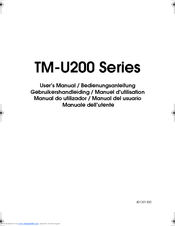
Manuals and User Guides for Epson TM-U200 Series. We have
8
Epson TM-U200 Series manuals available for free PDF download: Technical Manual, User Manual, Operator's Manual, Manual, Instructions Manual
Epson TM-U200 Series Technical Manual (187 pages)
Type A/AM
Brand:
Epson
| Category:
Printer
| Size: 3.64 MB
Table of Contents
Technical Manual
1
Fcc Compliance Statement
3
Table of Contents
7
Chapter 1 Features and General Specifications
11
Features
12
Printing Specifications
12
Character Specifications
14
Paper
15
Auto Cutter
16
Paper Roll Supply Device
16
Take-Up Device
16
Receive Buffer
16
Electrical Specifications
17
Ribbon Cassette
17
External Dimensions and Weight
18
Environmental Specifications
18
Reliability
19
Safety Standards (EMC Measured Using Seiko Epson's AC Adapter )
19
Printer Installation Position
20
Hardware Configuration
21
Main Unit Specifications
22
Paper Feed Motor
22
Carriage Motor
22
Print Head Unit
22
Home Position Sensor
22
Paper End Detector
23
Paper Roll Near-End Detector (Optional)
23
Connectors
24
Interface Connector
24
Power Supply Connector
24
Drawer Kick-Out Connector
25
Interface
27
RS-232 Serial Interface
27
Serial Interface (Option)
30
IEEE 1284 Parallel Interface
30
Buttons and Switches
34
Power Switch
34
Panel Button
34
DIP Switches
34
Panel Leds
37
Self-Test
38
Error Processing
39
Printer Operation When an Error Occurs
39
Data Receive Error
39
Buffer Full Printing
39
Detectors and Printing
39
Hexadecimal Dump
40
Performing a Hexadecimal Dump
40
Options
41
External Power Supply PS-170
42
Chapter 2 Mechanism Configuration and Operating Principles
43
Printer Mechanism Operating Principles
43
Print Mechanism Unit
44
Print Head Unit Movement
45
Wire Movement When a Single Dot Is Printed
45
Printing a Character (9X9 Font)
46
Paper Feed Mechanism Unit
47
Paper Loading (Semi-Automatic Loading)
48
Paper Feeding
48
Ribbon Feed Mechanism Unit
49
Ribbon Feeding
50
Detection Mechanism Unit
51
Home Position Detection Mechanism
51
Paper Detection Mechanism
52
Paper Roll Near-End Detection Mechanism (Optional)
52
Auto-Cutter Mechanism
52
Ribbon Switch Mechanism Unit
53
Switching from Black to Red
53
Releasing from Red to Black
54
Paper Take-Up Mechanism Unit
55
Electrical Circuitry Operating Principles
56
Hardware Configuration
56
Principles of Operation
59
Power Supply Circuitry
59
Control Circuitry
60
Reset Circuit
60
Cpu
61
Various Detector Circuits
66
Host Interface Circuit
66
Drawer Kick-Out Drive Circuit
67
DIP Switch Read Circuit
68
Printer Mechanism Driver Circuits
69
Print Head Driver Circuit
69
Paper Feed Motor Driver Circuit
70
Carriage Motor Driver Circuit
70
Auto-Cutter Driver Circuit
71
Chapter 3 Handling and Maintenance
73
Handling Precautions
73
Storage Precautions
73
Use Precautions
73
Paper Handling Precautions
73
Ribbon Cassette Handling Precautions
74
Replacing the Paper Roll
75
Replacing the Ribbon Cassette
80
Removing Jammed Paper
82
Using the Power Switch Cover
85
Inspection and Maintenance
86
Maintenance Procedures
86
Cleaning
87
Lubricants
88
Standard Lubrication
88
Lubrication Points
88
Tool List
90
Chapter 4 Troubleshooting
91
Self-Test
91
Initiating the Self-Test
91
Self-Test Standby
91
Ending the Self-Test
91
Troubleshooting Flowchart
92
Data from Host Is Not Printed Normally
99
Troubleshooting Tables
100
Error Types and Countermeasures
106
Chapter 5 Disassembly, Assembly, and Adjustment
111
Small Part Specifications
111
Disassembly
112
Removing the Fuse
112
Removing the Print Head Unit
112
Removing the Auto-Cutter
115
Removing the Main Circuit Board Assembly
116
Sub-Assembly a
119
Paper Feed Frame Unit Assembly
119
Main Assembly 1
125
Ribbon Switch Lever, Ribbon Release Spring, Ribbon Release Lever, Ribbon Intermediate Gear, Ribbon Transmission Gear, Ribbon Take-Up Assembly, and Ribbon Drive Plate Assembly
125
Main Assembly 2
127
Tension Plate Assembly
127
Main Assembly 3
128
Paper Feed Frame Assembly
128
Main Assembly 4
129
Carriage Motor Assembly
129
Main Assembly 5
130
Carriage Sub Assembly
130
Main Assembly 6
131
Carriage Shaft Assembly
131
Main Assembly 7
132
Adjustment Roller Shaft Holder Assembly
132
Main Assembly 8
133
Carriage Guide Shaft Assembly
133
Main Assembly 9
134
Belt Tension Spring Assembly
134
Main Assembly 10
135
Sensor Assembly
135
Main Assembly 11
136
Carriage Motor Heat Sink Assembly
136
Main Assembly 12
137
Print Head FPC Assembly
137
Main Assembly 13
139
Print Head Unit
139
Main Assembly 14
140
Left Cover Fixing Plate and Right Cover Fixing Plate
140
Main Assembly 15
141
Ribbon Frame Earth Plate
141
Main Assembly 16
142
Ribbon Frame Assembly, Ribbon Frame Spring, and Ribbon Frame Fixing Plate
142
Main Assembly 17
143
Thumb-Screw and Head Cover
143
Main Assembly 1 (Case Unit)
144
Lower Cutter Plate Assembly
144
Main Assembly 2 (Case Unit)
145
Upper Plate Assembly
145
Main Assembly 3 (Case Unit)
147
Main Circuit Board Assembly
147
Main Assembly 4 (Case Unit)
148
Inserting the Cables
148
Main Assembly 5 (Case Unit)
149
Lower Case Assembly
149
Main Assembly 6 (Case Unit)
150
Manual Cutter Assembly, Take-Up Belt and Auto-Cutter Fixing Plate
150
Main Assembly 7 (Case Unit)
153
Auto-Cutter Assembly
153
Main Assembly 8 (Case Unit)
157
Paper Roll Receive Rollers, Upper Case, Guide Roller, and Switch Panel Assemblies
157
Main Assembly 9 (Case Unit)
159
Interface Circuit Board Assembly and Connector Plate
159
Main Assembly 10 (Case Unit)
161
Lower Plate, ROM Cover, and Rubber Foot Assembly
161
Main Assembly 11 (Case Unit)
162
Take-Up Flange, Take-Up Flapper Spring and Take-Up Flaps Assemblies
162
Main Assembly 13 (Case Unit)
163
Main Cover Assembly
163
Main Assembly 14 (Case Unit)
164
Near-End Detector Assembly (Optional)
164
Adjustment
166
Platen Gap Adjustment
166
Appendix
167
RS-485 Serial Interface
167
Main Circuit Board Parts Layout
172
RS-232 Serial Interface Circuit Board Parts Layout
173
IEEE 1284 Parallel Interface Circuit Board Parts Layout
174
RS-485 Serial Interface Circuit Board Parts Layout
175
Main Circuit Board Diagram
177
RS-232 Serial Interface Circuit Board Diagram
178
UB-P01 IEEE 1284 Parallel Interface Circuit Board Diagram
179
UB-P02 IEEE 1284 Parallel Interface Circuit Board Diagram
180
RS-485 Serial Interface Circuit Board Diagram
181
Case Unit Overall Exploded Diagram
182
Printer Mechanism Unit Overall Exploded Diagram
183
Case Unit Lubrication Points Diagram
184
Printer Mechanism Unit Lubrication Points Diagram
185
Advertisement
Epson TM-U200 Series Technical Manual (169 pages)
Brand:
Epson
| Category:
Printer
| Size: 3.59 MB
Table of Contents
Technical Manual
1
Fcc Compliance Statement
3
Table of Contents
7
Chapter 1 Features and General Specifications
12
Features
12
Printing Specifications
12
Character Specifications
13
Paper
14
Auto-Cutter
15
Paper Roll Supply Device
15
Receive Buffer
15
Electrical Specifications
15
Ribbon Cassette
15
External Dimensions and Weight
16
Environmental Specifications
16
Reliability
17
Safety Standards
17
Printer Installation Position
17
Hardware Configuration
18
Main Unit Specifications
19
Paper Feed Motor
19
Carriage Motor
19
Print Head Unit
19
Home Position Sensor
19
Paper End Detector
20
Paper Roll Near-End Detector (Optional)
20
Connectors
20
Interface Connector
20
Power Supply Connector
21
Drawer Kick-Out Connector
21
Interface
23
RS-232 Serial Interface
23
Serial Interface (Option)
26
IEEE 1284 Parallel Interface
26
Buttons and Switches
29
Power Switch
29
Panel Button
29
DIP Switches
30
Panel Leds
32
Self-Test
32
Error Processing
33
Printer Operation When an Error Occurs
33
Data Receive Error
33
Buffer Full Printing
33
Detectors and Printing
33
Hexadecimal Dump
34
Performing a Hexadecimal Dump
34
Options
34
External Power Supply PS-170
34
Chapter 2 Mechanism Configuration and Operating Principles
37
Printer Mechanism Operating Principles
37
Print Mechanism Unit
38
Print Head Unit Movement
39
Wire Movement When a Single Dot Is Printed
39
Printing a Character (9X9 Font)
40
Paper Feed Mechanism Unit
41
Paper Loading (Semi-Automatic Loading)
42
Paper Feeding
42
Ribbon Feed Mechanism Unit
43
Ribbon Feeding
44
Detection Mechanism Unit
45
Home Position Detection Mechanism
45
Paper Detection Mechanism
46
Paper Roll Near-End Detection Mechanism (Optional)
46
Auto-Cutter Mechanism
46
Ribbon Switch Mechanism Unit
47
Switching from Black to Red
47
Releasing from Red to Black
47
Electrical Circuitry Operating Principles
48
Hardware Configuration
48
Memory Map
51
Principles of Operation
52
Power Supply Circuitry
52
Control Circuitry
53
Cpu
54
Various Detector Circuits
57
Host Interface Circuit
58
Drawer Kick-Out Drive Circuit
58
DIP Switch Read Circuit
59
Printer Mechanism Driver Circuits
61
Print Head Driver Circuit
61
Paper Feed Motor Driver Circuit
62
Carriage Motor Driver Circuit
62
Auto-Cutter Driver Circuit
63
Chapter 3 Handling and Maintenance
65
Handling Precautions
65
Storage Precautions
65
Use Precautions
65
Paper Handling Precautions
65
Ribbon Cassette Handling Precautions
66
Replacing the Paper Roll
66
Replacing the Ribbon Cassette
69
Removing Jammed Paper
71
Using the Power Switch Cover
76
Inspection and Maintenance
77
Cleaning
78
Lubricants
78
Standard Lubrication
78
Lubrication Points
79
Tool List
79
Chapter 4 Troubleshooting
81
Self-Test
81
Initiating the Self-Test
81
Self-Test Standby
81
Ending the Self-Test
81
Troubleshooting Flowchart
82
Data from Host Is Not Printed Normally
88
Troubleshooting Tables
89
Error Types and Countermeasures
95
Chapter 5 Disassembly, Assembly, and Adjustment
101
Small Part Specifications
101
Disassembly
102
Removing the Fuse
102
Removing the Print Head Unit
103
Removing the Auto-Cutter
105
Removing the Main Circuit Board Assembly
106
Sub-Assembly a
108
Paper Feed Frame Unit Assembly
108
Main Assembly 1
112
Ribbon Switch Lever, Ribbon Release Spring, Ribbon Release Lever, Ribbon Intermediate Gear, Ribbon Transmission Gear, Ribbon Take-Up Assembly, and Ribbon Drive Plate Assembly
112
Main Assembly 2
114
Tension Plate Assembly
114
Main Assembly 3
114
Paper Feed Frame Assembly
114
Carriage Motor Assembly
115
Main Assembly 4
115
Carriage Sub Assembly
116
Main Assembly 5
116
Main Assembly 6
117
Carriage Shaft Assembly
117
Main Assembly 7
118
Adjustment Roller Shaft Holder Assembly
118
Main Assembly 8
119
Carriage Guide Shaft Assembly
119
Main Assembly 9
119
Belt Tension Spring Assembly
119
Main Assembly 10
120
Sensor Assembly
120
Main Assembly 11
121
Carriage Motor Heat Sink Assembly
121
Main Assembly 12
122
Print Head FPC Assembly
122
Main Assembly 13
124
Print Head Unit
124
Main Assembly 14
125
Left Cover Fixing Plate and Right Cover Fixing Plate
125
Main Assembly 15
126
Ribbon Frame Earth Plate
126
Main Assembly 16
126
Ribbon Frame Assembly, Ribbon Frame Spring and Ribbon Frame Fixing Plate
126
Main Assembly 17
128
Thumb-Screw and Head Cover
128
Main Assembly 1 (Case Unit)
129
Lower Cutter Plate Assembly
129
Main Assembly 2 (Case Unit)
130
Upper Plate Assembly
130
Main Assembly 3 (Case Unit)
131
Main Circuit Board Assembly
131
Main Assembly 4 (Case Unit)
133
Inserting the Cables
133
Main Assembly 5 (Case Unit)
133
Lower Case Assembly
133
Main Assembly 6 (Case Unit)
135
Manual Cutter Assembly and Auto-Cutter Fixing Plate
135
Main Assembly 7 (Case Unit)
137
Auto-Cutter Assembly
137
Main Assembly 8 (Case Unit)
139
Paper Roll Receive Rollers, Upper Case, Guide Roller and Switch Panel Assemblies
139
Main Assembly 9 (Case Unit)
142
Interface Circuit Board Assembly and Connector Plate
142
Main Assembly 10 (Case Unit)
143
Lower Plate, ROM Cover, and Rubber Foot Assembly
143
Main Assembly 11 (Case Unit)
144
Main Cover Assembly
144
Main Assembly 12 (Case Unit)
145
Near-End Detector Assembly (Optional)
145
Adjustment
148
Platen Gap Adjustment
148
Appendix
151
RS-485 Serial Interface
151
Main Circuit Board Parts Layout
156
RS-232 Serial Interface Circuit Board Parts Layout
157
IEEE 1284 Parallel Interface Circuit Board Parts Layout
158
RS-485 Serial Interface Circuit Board Parts Layout
159
Main Circuit Board Diagram
161
RS-232 Serial Interface Circuit Board Diagram
162
IEEE 1284 Parallel Interface Circuit Board Diagram
163
RS-485 Serial Interface Circuit Board Diagram
164
Printer Mechanism Unit Overall Exploded Diagram
165
Case Unit Overall Exploded Diagram
166
Printer Mechanism Unit Lubrication Points Diagram
167
Case Unit Lubrication Points Diagram
168
Epson TM-U200 Series Operator's Manual (55 pages)
Type A
Brand:
Epson
| Category:
Printer
| Size: 0.66 MB
Table of Contents
Fcc Compliance Statement
6
For American Users
6
For Canadian Users
6
Declaration of Conformity
7
About this Manual
9
Table of Contents
10
Chapter 1 Setting up the Printer
11
Unpacking
11
Selecting the Place
11
Attaching the Paper Roll Near-End Detector (Option)
12
Connecting the Printer to the Computer
15
Serial Interface
17
Parallel Interface
17
Grounding the Printer
19
Connecting the Power Supply
20
Installing the Ribbon Cassette
22
Installing the Paper Roll
25
Running the Self Test
30
Setting the DIP Switches
31
Model with Serial Interface Dip-Switch Functions
32
Model with Parallel Interface Dip-Switch Functions
33
Using the Power Switch Cover
35
Affixing the Fastening Tape (Option)
36
Chapter 2 Using the Printer
37
Operating the Control Panel
37
Switch
37
Button
37
Indicator Lights
38
Chapter 3 Troubleshooting
40
Troubleshooting
40
General Problems
40
Printing Problems
40
Removing Jammed Paper
42
Hexadecimal Dump
46
Chapter 4 Reference Information
48
Printing Specifications
48
Character Specifications
49
Paper Specifications
50
Electrical Specifications
52
Safety and EMI Standards Applied
52
Reliability
53
Environmental Conditions
54
Interface Specifications
55
Drawer Kick-Out Specifications
55
Advertisement
Epson TM-U200 Series User Manual (72 pages)
User Manual
Brand:
Epson
| Category:
Printer
| Size: 2.26 MB
Table of Contents
Printer Parts
2
Single Color
2
Dip Switch Tables
2
Emc and Safety Standards Applied
3
Fcc Compliance Statement for American Users
3
For Canadian Users
3
Safety Precautions
4
Caution Labels
5
Control Panel
6
Using the Power Switch Cover
6
Installing the Ribbon Cassette
7
Installing the Paper Roll
7
Troubleshooting
9
Einlegen der Papierrolle
18
Adaptateur Secteur
32
Panneau de Commande
34
Manual Do Utilizador
39
Painel de Controlo
42
Manual del Usuario
49
Precauciones de Seguridad
50
Panel de Control
53
Precauzioni DI Sicurezza
60
Pannello DI Controllo
62
Risoluzione Dei Problemi
64
Rimozione Della Carta Inceppata
65
Epson TM-U200 Series User Manual (69 pages)
TM-U200 Series
Brand:
Epson
| Category:
Printer
| Size: 0.75 MB
Table of Contents
Printer Parts
2
Single Color
2
Dip Switch Tables
2
Emc and Safety Standards Applied
3
Fcc Compliance Statement for American Users
3
For Canadian Users
3
Safety Precautions
4
Caution Labels
5
Control Panel
6
Using the Power Switch Cover
6
Installing the Ribbon Cassette
7
Installing the Paper Roll
7
Troubleshooting
9
Removing Jammed Paper
9
Einlegen der Papierrolle
18
Adaptateur Secteur
32
Panneau de Commande
34
Manual Do Utilizador
39
Painel de Controlo
42
Manual del Usuario
49
Precauciones de Seguridad
50
Cartucho de Cinta
52
Panel de Control
53
Precauzioni DI Sicurezza
60
Pannello DI Controllo
62
Risoluzione Dei Problemi
64
Rimozione Della Carta Inceppata
65
Epson TM-U200 Series Operator's Manual (48 pages)
Type (B)
Brand:
Epson
| Category:
Printer
| Size: 0.7 MB
Table of Contents
Control Panel
3
Printer Parts
3
Fcc Compliance Statement
5
For American Users
5
For Canadian Users
5
Table of Contents
6
About this Manual
8
Chapter 1 Setting up the Printer
9
Unpacking
9
Selecting the Place
10
Attaching the Paper Roll Near-End Detector (Option)
10
Connecting the Printer to the Computer
12
Connecting the Printer to the Drawer
14
Grounding the Printer
16
Connecting the Power Supply
17
Installing the Ribbon Cassette
19
Installing the Paper Roll
21
Running the Self Test
25
Setting the DIP Switches
26
Using the Power Switch Cover
29
Affixing the Fastening Tape (Option)
30
Chapter 2 Using the Printer
31
Operating the Control Panel
31
Switch
31
Button
31
Indicator Lights
32
Chapter 3 Troubleshooting
34
Troubleshooting
34
General Problems
34
Printing Problems
34
Removing Jammed Paper
36
Hexadecimal Dump
40
Chapter 4 Reference Information
42
Printing Specifications
42
Character Specifications
43
Paper Specifications
44
Electrical Specifications
46
Safety and EMI Standards Applied
46
Reliability
47
Environmental Conditions
47
Interface Specifications
48
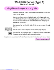
Epson TM-U200 Series Manual (13 pages)
How to connect an Epson POS Printer with an Ethernet Adapter
Brand:
Epson
| Category:
Printer
| Size: 0.22 MB
Table of Contents
Resetting the Adapter
4
Installation Steps
8
Installing the Printer Driver in Windows
10
Testing the Printer
12
Printing Is Slow
13
Epson TM-U200 Series Instructions Manual (12 pages)
How to connect Printer with a Wireless Adapter
Brand:
Epson
| Category:
Printer
| Size: 0.19 MB
Table of Contents
Network Setup
2
Installing the Printer Driver in Windows
8
Testing the Printer
10
Wireless Problems
11
Printing Is Slow
11
Advertisement
Related Products
Epson TM U200D - B/W Dot-matrix Printer
Epson TM-U200D series
Epson TM-U200PD
Epson TM-U200P
Epson TM-U200B/D
Epson TM-U220 Series
Epson TM-U210
Epson TM-U210A
Epson TM-U210D
Epson TM-U220 Type A
Epson Categories
Printer
Projector
All in One Printer
Scanner
Printer Accessories
More Epson Manuals
Login
Sign In
OR
Sign in with Facebook
Sign in with Google
Upload manual
Upload from disk
Upload from URL