Epson U200B - TM Color Dot-matrix Printer Operator's Manual
Type (b)
Hide thumbs
Also See for U200B - TM Color Dot-matrix Printer:
- User manual (45 pages) ,
- User manual (69 pages)
Table of Contents
Advertisement
Quick Links
Download this manual
See also:
User Manual
TM-U200 Series Type(B)
Using this online operator's guide
The words on the left side of this screen are bookmarks for all the
topics in this guide.
Use the scroll bar next to the bookmarks to find any topic you
want. Click a bookmark to instantly jump to its topic. (If you wish,
you can increase the size of the bookmark area by dragging the
dividing bar to the right.)
Use the scroll bar on the right side of this screen to move through
the text.
Use the zoom tools to magnify or reduce the page display.
Click the Find button if you want to search for a particular term.
(However, using the bookmarks is usually quicker.)
Complete online documentation for Acrobat Reader is located in the Help directory for Acrobat Reader.
Operator's Manual
Return to main menu
Advertisement
Table of Contents

Subscribe to Our Youtube Channel
Related Manuals for Epson U200B - TM Color Dot-matrix Printer


Summary of Contents for Epson U200B - TM Color Dot-matrix Printer
- Page 1 TM-U200 Series Type(B) Operator’s Manual Using this online operator’s guide The words on the left side of this screen are bookmarks for all the topics in this guide. Use the scroll bar next to the bookmarks to find any topic you want.
- Page 2 TM-U200 Series (Type B) Operator’s Manual 400802000...
-
Page 3: Printer Parts
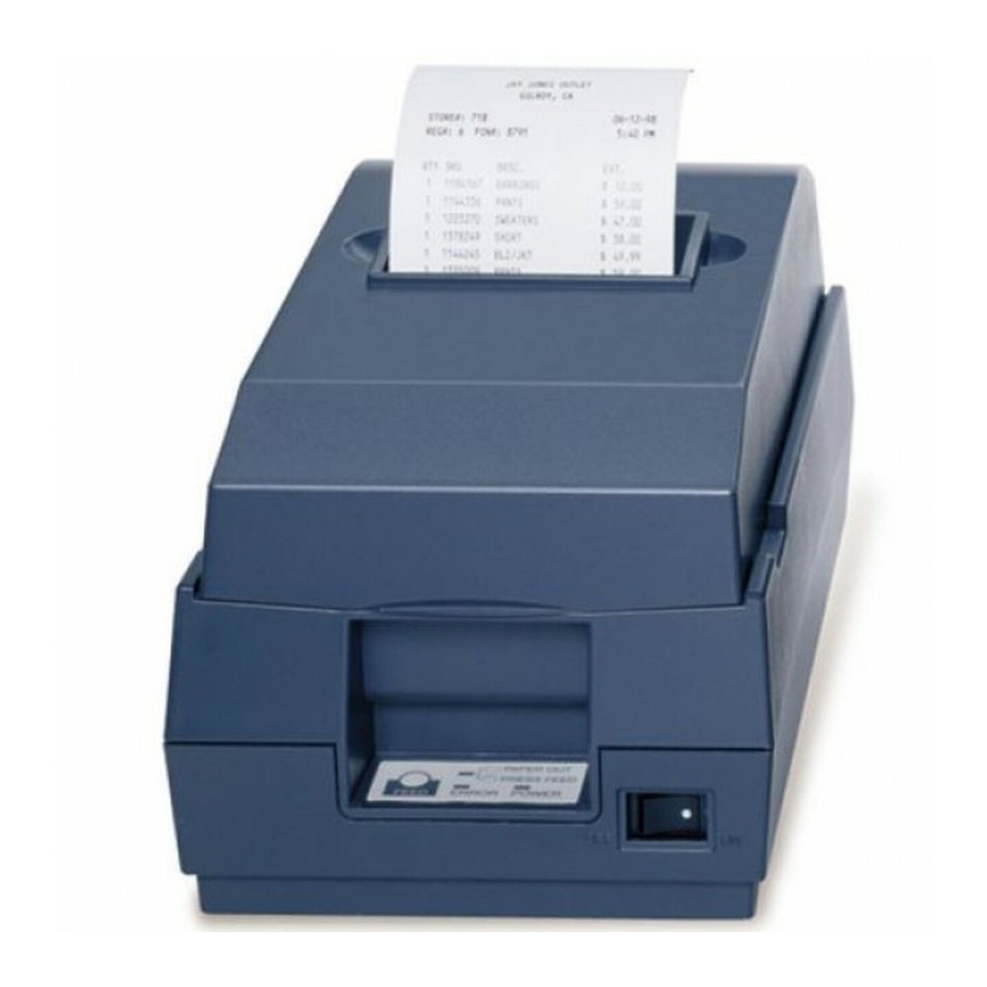
Printer parts Printer coverr Drawer kick-out connectors Interface Power connector Connector Model with Serial Interface Model with Parallel Interface DIP switches Power switch Control panel PAPER FEED PAPER OUT light button ERROR light POWER light... - Page 4 Seiko Epson Corporation. No patent liability is assumed with respect to the use of the information contained herein. While every precaution has been taken in the preparation of this book, Seiko Epson Corporation assumes no responsibility for errors or omissions.
-
Page 5: Fcc Compliance Statement
FCC CLASS A FCC Compliance Statement For American Users This equipment has been tested and found to comply with the limits for a Class A digital device, pursuant to Part 15 of the FCC Rules. These limits are designed to provide reasonable protection against harmful interference when the equipment is operated in a commercial environment. -
Page 6: Table Of Contents
Contents Chapter 1 Setting Up the Printer Unpacking ............1-1 Selecting the Place . - Page 7 Introduction Features The TM-U200 Series printers are one-station printers for ECR and POS use that can be used for printing the results of weighing or measuring. TM-U200 Series (Type B) has the following 2 models. Two-color type with a serial interface Two-color type with a parallel interface The main features of the TM-U200 Series printers are the following: High-speed printing through logic-seeking control...
-
Page 8: About This Manual
About This Manual Setting Up and Using Chapter 1 contains information on unpacking the printer, setting it up, running the self test, and setting the DIP switches. Chapter 2 contains information on using the printer. Chapter 3 contains troubleshooting information. Reference Chapter 4 contains specifications. -
Page 9: Chapter 1 Setting Up The Printer
Chapter 1 Setting Up the Printer Unpacking When you unpack the TM-U200 Series Type B printer, make sure you have these items. Printer Power supply (The power supply may not be included with the printer with the serial interface.) Hexagonal lock screw (2 pcs) Ribbon cassette (only for the printer with the serial interface and only included when the... -
Page 10: Selecting The Place
Selecting the Place Place the printer on a surface that is as horizontal as possible. The printer should be installed so that it does not move or vibrate during paper cutting or the drawer kick-out operation. Fastening tape is available as an option. Attaching the Paper Roll Near-End Detector (Option) If you do not have a paper roll near-end detector or do not want to attach it, skip this section. - Page 11 3. Two spacers are included with the near-end detector. See the illustration below and decide whether or not you want to use them. Use them if you want the near-end detector to be triggered when distance A is 3 to 4 mm; otherwise it will be triggered when distance A is approximately 6 mm.
-
Page 12: Connecting The Printer To The Computer
5. Connect the connector for the detector to CN11 of the printer. Position the cable as shown in the illustration. 6. Replace the cover and fasten it with the four screws. Connecting the Printer to the Computer You need an appropriate serial interface or parallel interface cable to connect your computer to the printer. - Page 13 Note: Your printer comes with inch-type hexagonal lock screws installed. If you plan to use an interface cable that requires millimeter-type lock screws, replace the inch-type screws with the enclosed millimeter-type screws by using a hex screwdriver (5 mm). To distinguish the two types of screws, see the illustration below.
-
Page 14: Connecting The Printer To The Drawer
Connecting the Printer to the Drawer WARNING: Use a drawer that matches the printer specification. Using an improper drawer may damage the drawer as well as the printer. Plug the drawer cable into the drawer kick-out connector on the bottom of the printer next to the computer interface connector. Model with Serial Interface Model with Parallel... - Page 15 Den Drucker an die Lade anschließen Das Kabel der Lade an die Schnappsteckerbuchse (neben der Schnittstellenbuchse) an der Unterseite des Druckers anschließen. Model with Serial Interface Model with Parallel Model Interface ACHTUNG: Kein Telefonkabel an die Schnappsteckerbuchse anschließen. Setting Up the Printer 1–7...
-
Page 16: Grounding The Printer
Grounding the Printer You need a ground wire to ground your printer. Make sure the wire meets the specification below. Thickness of wire: AWG 18 or equivalent Diameter of terminal to be attached: 1. Make sure the printer is turned off. 2. -
Page 17: Connecting The Power Supply
CAUTION: Do not connect the enclosed power supply to the EPSON customer display DM-D101 or DM-D202. This can damage the customer display and the power supply. However, you can connect this power supply to the EPSON customer display DM-D101 II or DM-D202 II. - Page 18 2. Plug the power supply’s cable into the printer’s connector as shown below. Note that the flat side of the connector faces down. Model with Serial Interface Model with Parallel Interface 3. Plug the power supply’s cord into an outlet. If you ever need to remove the cable, unplug the power supply’s cord from an outlet and then grasp the connector firmly at the arrow mark and pull it straight out.
-
Page 19: Installing The Ribbon Cassette
Be sure the printer is not receiving data when you replace a ribbon cassette; otherwise, data may be lost. Note: Use the EPSON ERC-38 ribbon cassette for your printer. 1. Open the printer cover. 2. Turn the ribbon cassette’s knob in the direction of the arrow to take up any slack in the ribbon. - Page 20 Note: Make sure the ribbon is installed between the print head and the platen without wrinkles or creases. 5. Turn the ribbon cassette’s knob 5 or 6 times in the direction of the arrow again to take up any slack in the ribbon. 6.
-
Page 21: Installing The Paper Roll
Installing the Paper Roll Notes: Be sure to use roll paper that meets the specifications. Do not use paper rolls that have the paper glued to the core because the printer cannot detect the paper end correctly. (However, if you stop printing using the optional paper roll near-end detector, you can use the glued type of paper rolls.) 1. - Page 22 Note: Be sure to note the correct direction that the paper comes off the roll as shown below. 4. Open the auto cutter by pulling the tab up and toward you. 1–14 Setting Up the Printer...
- Page 23 5. Hold both edges of the paper and insert it straight into the paper slot. The printer feeds the paper automatically. 6. If the paper is not coming out of the manual cutter, press the PAPER FEED button until the paper comes out. 7.
- Page 24 8. Close the auto cutter by using the tab. 9. Close the printer cover. 10. When the PAPER OUT light blinks, press the PAPER FEED button to set the printer on line. To remove the paper roll, follow the steps below. 1.
-
Page 25: Running The Self Test
4. Press the PAPER FEED button to remove the remaining paper. Note: Do not pull the remaining paper in the opposite direction of paper feeding. Running the Self Test Any time that you want to check the performance of your printer you can run the self test described below. -
Page 26: Setting The Dip Switches
Setting the DIP Switches CAUTION: Turn off the printer while removing the DIP switch cover to prevent an electrical short, which can damage the printer. You can change your serial interface and print column settings by changing the DIP switch settings. 1. - Page 27 Model with Serial Interface DIP-Switch Functions DIP Switch Set 1 Switch Function Data reception error Ignored Prints ”?” Receive buffer capacity 40 bytes Approximately 1K byte Handshaking XON/XOFF DTR/DSR Word length 7 bits 8 bits Parity check Parity selection Even Baud rate 4800 BPS 9600 BPS...
- Page 28 Model with Parallel Interface DIP-Switch Functions DIP Switch Set 1 Switch Function Auto-line feed Enabled Disabled Receive buffer capacity 40 bytes Approximately 1K byte Undefined Undefined Undefined Undefined Undefined Handshaking Receive buffer full Off line, (BUSY condition) or reading data receive buffer full, or reading data...
-
Page 29: Using The Power Switch Cover
Using the Power Switch Cover You can use the provided power switch cover to protect the power switch from accidental or improper operation. Attach the cover as shown in the illustration below. You can turn the power on or off with the switch cover attached by inserting a pointed object (like a ball point pen) through either of the two small holes on the switch cover. -
Page 30: Affixing The Fastening Tape (Option)
Affixing the Fastening Tape (Option) Two sets of tape are included as an option to fasten your printer to a countertop or other surface. Follow the steps below: 1. Clean the countertop or other surface where the printer will be installed. -
Page 31: Chapter 2 Using The Printer
Chapter 2 Using the Printer Operating the Control Panel You can feed paper with the button on the control panel. The indicator lights help you monitor the printer’s status. Switch The power switch on the front of the printer turns the printer on and off. -
Page 32: Indicator Lights
Indicator lights The control panel lights provide information on printer conditions. (Green) POWER The POWER light is on when the printer power is on. PAPER OUT (Red) This light is on when the paper roll is at the end or near the end. This light blinks in the following cases. - Page 33 CAUTION: The print head becomes very hot during printing. Allow it to cool before you reach into the printer. Note: The power switch and PAPER FEED button can also be used to start the self test. Using the Printer 2-3...
-
Page 34: Chapter 3 Troubleshooting
Chapter 3 Troubleshooting Solving Common Problems This chapter gives solutions to some of the more common printer problems. General problems The lights on the control panel do not come on. Make sure the power supply cables are correctly plugged into the printer, the power unit, and to the power outlet. - Page 35 The ERROR light is off, but nothing is printed. Try to run the self test to check that the printer works properly. See the self test instructions in Chapter 1 to run the self test. If the self test does not work, contact your dealer or a qualified service person.
-
Page 36: Removing Jammed Paper
A line of dots is missing in the printout. The print head may be damaged. Stop printing and contact your dealer or a qualified service person. Removing jammed paper Follow these steps to clear a paper jam: CAUTION: The print head becomes very hot during printing. Allow it to cool before you reach into the printer. - Page 37 5. Remove the jammed paper by pulling it in the direction of paper feeding. Note: Do not pull the jammed paper in the opposite direction of paper feeding. 6. If paper still remains in the printer, follow the steps below. 7.
- Page 38 8. Loosen the screw securing the print head cover. Turn the screw only until you can tilt it as shown in the illustration. Note: Do not remove the screw from the print head cover. Troubleshooting 3-5...
- Page 39 9. Lift up the print head cover. 10. Remove all the jammed paper. Note: Do not pull the jammed paper in the direction opposite of paper feeding. 11. Replace the print head cover and secure it with the screw. 12. Replace the ribbon cassette and close the auto cutter 3-6 Troubleshooting...
-
Page 40: Hexadecimal Dump
13. .If the auto cutter blade is not in its normal position (if you can see the blade in the auto cutter slit, the blade is not in the normal position), insert a screwdriver into the right side of the auto cutter, and turn the gear inside to move the blade to the normal position. - Page 41 To use the hex dump feature, follow these steps: 1. After you make sure the printer is off, set DIP switch 1-2 to ON. 2. Turn on the printer while you hold down the PAPER FEED button; then release and press the PAPER FEED button quickly. Note: Perform releasing and pressing the PAPER FEED button before the printer finishes initializing;...
-
Page 42: Chapter 4 Reference Information
Chapter 4 Reference Information Printing Specifications Printing method: Serial impact dot-matrix Head wire 9-pin serial configuration configuration: Printing direction: Bi-directional, logic-seeking Characters/line See table on page 4-2. (default): See table on page 4-2. Character spacing (default) Fonts A and B: Printing speed: Approximately 3.5 lines/second (40 columns, 16 characters/inch) -
Page 43: Character Specifications
Character Specifications Number of Alphanumeric characters: 95 characters: Extended graphics: 128 x 8 pages, International characters: 32 Character structure: 7 x 9 (the total number of dots in horizontal: 400 in half dot units) 9 x 9 (the total number of dots in horizontal: 400 in half dot units) Character size: See table below. -
Page 44: Paper Specifications
Paper Specifications Paper feed method: Friction feed Paper feed pitch: Default 4.233 mm (1/6 inch) Can be set in units of 0.176 mm (1/144 inch) by the ESC 2 and ESC 3 commands. Paper feed speed: Approximately 25 lines/second (4.17 inches/second) (continuous feeding) Paper size and weight: Normal paper (single-ply) - Page 45 Pressure-sensitive paper Maximum 1 original + 1 copy Size: Width 76 mm ± 0.5 mm (3.0" ± 0.02") Maximum 83 mm (3.27") outside diameter: Thickness: 0.05 to 0.08 mm (.0020 to .0031") (Total thickness should be 0.13 mm or less with a combination of 0.05 to 0.08 mm sheets.) Recommended...
-
Page 46: Electrical Specifications
Electrical Specifications Power voltage: 24 VDC ± 10% One of the following 5 AC adapters is Packaged AC adapter: selected, depending on local power: Factory setting Voltage Manufacturer Number Japan 100 V ± 10 %, 50/60Hz PA-6508 North America 120 V ± 10 %, 60 Hz PB--6509 Europe (Germany) 230 V ±... -
Page 47: Reliability
Reliability Mechanism: MCBF: 5,000,000 lines (excluding the print head) Life: 7,500,000 lines 800,000 automatic cut (The printer is defined to have reached the end of its life when it cannot function properly because of wearing out of the main parts (motors, solenoids, frames, shafts) Print head life: 100 million characters (when printing... -
Page 48: Interface Specifications
Parallel interface: IEEE 1284 compatible (Nibble/Byte Modes) Note: The interface is a factory installed option. One of the interfaces (RS-232, RS-485, or parallel) is already installed. Note: Refer to the EPSON TM-U200 Series (Type B) Specification for details. 4-8 Reference Information...
Need help?
Do you have a question about the U200B - TM Color Dot-matrix Printer and is the answer not in the manual?
Questions and answers