Epson TM-U200 Series Technical Manual
Type a/am
Hide thumbs
Also See for TM-U200 Series:
- User manual (69 pages) ,
- Manual (13 pages) ,
- Operator's manual (55 pages)

Related Manuals for Epson TM-U200 Series


Summary of Contents for Epson TM-U200 Series
-
Page 1: Technical Manual
C o n fid e n tia l Technical manual TM-U200 Series Type A/AM Copied Date Copied by English 400950100... - Page 2 INFORMATION OR ANY OTHER INFORMATION IN THE DOCUMENT, INCLUDING (WITHOUT LIMITATION) ANY WARRANTY OF TITLE OR NON-INFRINGEMENT. Seiko Epson has no liability for loss or damage arising from or relating to your use of or reliance on the information on the document.
-
Page 3: Fcc Compliance Statement
C o n fid e n tia l TM-U200 Series (Type A/AM) Technical Manual FCC CLASS A FCC Compliance Statement For American Users This equipment has been tested and found to comply with the limits for a Class A digital device, pursuant to Part 15 of the FCC Rules. - Page 4 C o n fid e n tia l Introduction TM-U200 Series (Type A/AM) printers are one-station printers for ECR and POS use that can print the results of weighing or measuring. TM-U200 series (Type A/AM) has the following 2 types.
- Page 5 C o n fid e n tia l TM-U200 Series (Type A/AM) Technical Manual Notes and Cautions Note: Notes have important information and useful tips on the operation of your printer. CAUTION: Cautions must be observed to avoid damage to your equipment.
- Page 6 C o n fid e n tia l Revision Sheet Revision Page Altered Items and Contents Rev. A...
-
Page 7: Table Of Contents
Safety Standards (EMC measured using Seiko Epson’s AC adapter ) ....... - Page 8 C o n fid e n tia l Print head unit movement ............... 2-3 Wire movement when a single dot is printed .
- Page 9 C o n fid e n tia l TM-U200 Series (Type A/AM) Technical Manual Self-test Standby ................4-1 Ending the Self-test .
- Page 10 C o n fid e n tia l Main Assembly 4 (Case Unit) ............... . . 5-38 Inserting the cables .
-
Page 11: Chapter 1 Features And General Specifications
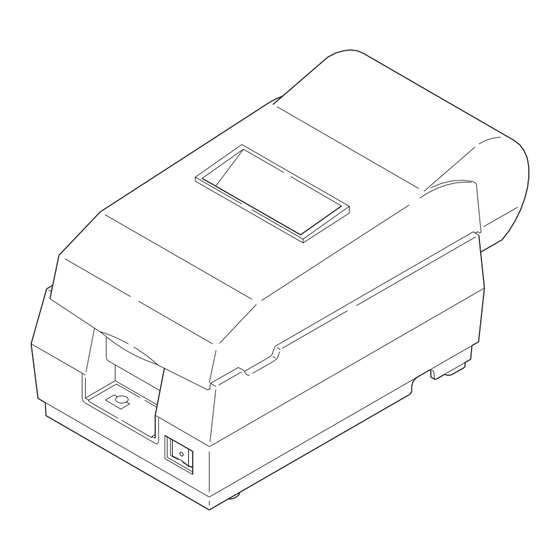
PAPER FEED button (PAPER OUT/PRESS FEED) POWER LED ERROR LED Power Supply Connector PROM Drawer Kick Connector Frame Ground Screw DIP Switches Frame Ground Screw Interface Connector Figure 1-1 TM-U200 Series (Type A/AM) appearance Rev. A Features and General Specifications 1-1... -
Page 12: Features
C o n fid e n tia l Features Printing Specifications Printing method: Serial impact dot-matrix Head wire configuration: 9-pin serial type 0.353 mm (0.014") 0.29 mm (0.01") (wire diameter) 0.317 mm (0.012") Figure 1-2 Dot configuration Dot pitch: Vertical: 0.353 mm (1/72"), Horizontal: 0.317mm (0.012") Dot wire diameter 0.29 mm (0.01") Printing direction:... - Page 13 C o n fid e n tia l TM-U200 Series (Type A/AM) Technical Manual Note: If the print duty ratio is too high, the operation of the print head is stopped by the duty limit. In such circumstances, the print speeds shown above cannot be guaranteed.
-
Page 14: Character Specifications
C o n fid e n tia l Character Specifications Character sets: Alphanumeric: 95 International: 32 Graphics: 128 x 8 pages Kanji: JIS Level 1, Level 2 (JIS X0208-1990) (Type AM only) Character structure: 7 x 9 with 400 half-dot positions per line 9 x 9 with 400 half-dot positions per line 16 x 16 with 400 half-dot positions per line (Type AM only) 1.24 mm (0.049") -
Page 15: Paper
C o n fid e n tia l TM-U200 Series (Type A/AM) Technical Manual Paper Paper types: Paper roll:Plain paper or pressure-sensitive paper Paper roll width: 76 ± 0.5 mm (2.99 ± .020") Paper roll maximum 83 mm (3.27") diameter:... -
Page 16: Auto Cutter
C o n fid e n tia l Cutting position (auto-cutter) Cutting position (manual cutter) 27 mm (1.063") 20.2 mm (0.79") (*1) (*2) 63.34 mm (2.49") Maximum of 200 dots, 400 positions [6.76 mm (0.27")] [5.9 mm (0.23")] 76 mm (2.99") Figure 1-4 Printing area (*1) This dimension shows the distance from the manual cutter to the print position. -
Page 17: Electrical Specifications
Red:750,000 characters (with continuous printing at 25° C [77° F]) (*1)Ribbon life is based on the following conditions: Character font:7 x 9 font (with descenders) Print pattern:ASCII 96-character rolling pattern. See the specification published by EPSON for the print pattern example. Note: Malfunctions and other problems may occur if a ribbon cassette other than the specified one is used. -
Page 18: External Dimensions And Weight
295 mm (11.60") Depth: Weight: Approximately 2.5 kg (5.5 lb) Color: EPSON standard color Environmental Specifications Temperature: Operating: 5° to 35° C (41° to 95° F) Storage: –10° to 50° C (14° to 122° F), except paper and ribbon Humidity:... -
Page 19: Reliability
Directions: Lift one edge and release it (for all 4 edges) Reliability Life Mechanism: 7,500,000 lines (See the TM-U200 Series (Type B) Specification for the print color switching number. 150 million characters (using an average of 2 dots/wire per Print head: character.) (The print pattern is shown in the TM-U200 Series... -
Page 20: Printer Installation Position
C o n fid e n tia l Printer Installation Position Install the printer horizontally. Make sure it does not tilt more than 15°. The printer must also be installed so that it does not move or vibrate during paper cutting or the drawer kick-out operation. -
Page 21: Hardware Configuration
Paper end detector Paper feed motor Print head unit Home position sensor Carriage motor Paper roll near-end detector (optional) Interface circuit board Main circuit board Figure 1-6 TM-U200 Series (Type A/AM) main unit configuration Rev. A Features and General Specifications 1-11... -
Page 22: Main Unit Specifications
C o n fid e n tia l Main Unit Specifications Paper Feed Motor Type: 4-phase, 48-polarity, PM-type stepping motor Drive voltage: 24 VDC ± 10% 39.5 Ω ± 5 Ω at 25° C (77° F), per phase Winding resistance: Current consumption: Peak: 1.5 A in worst case Average: 400 mA at 24 VDC, 25°... -
Page 23: Paper End Detector
C o n fid e n tia l TM-U200 Series (Type A/AM) Technical Manual Paper End Detector Type: Microswitch Voltage: 5 VDC ± 5% Output level: High when paper end is detected Paper Roll Near-end Detector (Optional) Type: Microswitch Voltage: 5 VDC ±... -
Page 24: Connectors
C o n fid e n tia l Connectors Drawer kick-out Frame ground Interface Frame ground Power supply connector screw screw connector connector Figure 1-7 Connector panel (serial interface) Drawer kick-out Power supply Frame ground Frame ground Interface connector screw screw connector connector... -
Page 25: Drawer Kick-Out Connector
C o n fid e n tia l TM-U200 Series (Type A/AM) Technical Manual Drawer Kick-Out Connector A pulse specified by the ESC p command is output to the drawer kick-out connector. The host can confirm the status of the input signal by using the GS a, GS r, or DLE EOT commands. - Page 26 C o n fid e n tia l Notes: Two driver transistors cannot be energized simultaneously. The drawer drive duty must be as shown below: ON time ≤ 0.2 (ON time + OFF time) Be sure to use the printer power supply (connector pin 4) for the drawer power source. CAUTION: Do not connect a telephone line to the drawer kick-out connector;...
-
Page 27: Interface
C o n fid e n tia l TM-U200 Series (Type A/AM) Technical Manual Interface RS-232 Serial Interface Data transmission: Serial (compatible with RS-232) Synchronization: Asynchronous Handshaking: DTR/DSR or XON/XOFF control Signal levels: MARK = -3 to -15 V: Logic 1/OFF... - Page 28 C o n fid e n tia l Interface Connector Pin Assignments RS-232 interface connector pin assignments and functions Pin number Signal name Function — Frame ground Transmit data Receive data Same as the DTR signal This signal indicates whether the host computer can receive data. SPACE indicates the host computer can receive data, and MARK indicates the host computer cannot receive data.
- Page 29 C o n fid e n tia l TM-U200 Series (Type A/AM) Technical Manual The printer ignores data received when the remaining space in the receive buffer is 0 bytes. XON is not transmitted when the receive buffer is full.
-
Page 30: Serial Interface (Option)
C o n fid e n tia l Serial interface connection example Printer Host Notes: Set handshaking so that transmitted data can be received. Transmit data to the printer after turning on the power and initializing the printer. RS-485 Serial Interface (option) Refer to the Appendix for details. - Page 31 C o n fid e n tia l TM-U200 Series (Type A/AM) Technical Manual bidirectional. Both modes fail to proceed concurrently in compatibility mode, causing half duplex transmission. The IEEE 1284 nibble/byte modes are under development in draft form and may be subject to change.
- Page 32 C o n fid e n tia l Interfacing conditions must all be based on the TTL level to meet the characteristics described below. In addition, both the rise and fall time of each signal must be 0.5 µ s or less. Data transmission must not ignore the ACK or BUSY signal.
- Page 33 C o n fid e n tia l TM-U200 Series (Type A/AM) Technical Manual When ASB status is received following this, a total of eight (8) bytes of ASB will be transmitted as follows: Accumulated ASB ( + + ).
-
Page 34: Buttons And Switches
C o n fid e n tia l Buttons and Switches Power Switch Type: Rocker switch Function: The power switch turns the power on or off. Note: Turn on the power only after connecting the power supply. Panel Button The panel button is enabled or disabled by the ESC c 5 command. This button is inactive if it is disabled. - Page 35 C o n fid e n tia l TM-U200 Series (Type A/AM) Technical Manual DIP switch 2 DIP Switch Function Print column selection 42CPL/35CPL 40CPL/33CPL 9 font/9 9 font For internal use only Fixed to ON. 3 - 5 Undefined For internal use only.
- Page 36 C o n fid e n tia l Notes: Do not change the settings of DIP switches 2-2 (Fixed to ON), 2-4 (fixed to ON) and 2-6 (Fixed to OFF). Changes in DIP switch settings are recognized only when printer power is turned on or reset using the interface.
-
Page 37: Panel Leds
C o n fid e n tia l TM-U200 Series (Type A/AM) Technical Manual Panel LEDs Power (POWER) LED: Green 24 V power supply is stable. Off: 24 V power supply is not stable. Paper roll near-end (PAPER OUT) LED: Paper roll near-end is detected. -
Page 38: Self-Test
C o n fid e n tia l Self-test The printer has a self-test function that checks the following: Control circuit functions Printer mechanisms Print quality Control ROM version DIP switch settings. See Chapter 4 for instructions on running a self-test. 1-28 Features and General Specifications Rev. -
Page 39: Error Processing
C o n fid e n tia l TM-U200 Series (Type A/AM) Technical Manual Error Processing Printer Operation When an Error Occurs The printer executes the following operations upon detecting an error: Serial interface All mechanical operations stop. DTR signal is set to MARK (only when DTR/DSR is selected and DIP switch 1-8 is off). -
Page 40: Hexadecimal Dump
C o n fid e n tia l Hexadecimal Dump This function prints data transmitted from the host computer in hexadecimal numbers and in their corresponding ASCII characters. Performing a Hexadecimal Dump 1. Turn the printer power off. 2. Set DIP switch 1-2 to on to select 40 bytes for the receive buffer capacity. 3. -
Page 41: Options
C o n fid e n tia l TM-U200 Series (Type A/AM) Technical Manual Options Paper roll near end detector (dealer option) External power supply PS-170 Printer fastening tape (DF-10) RS-485 serial interface IEEE 1284 compatible interface board (Bidirectional parallel: factory-installed) RS-232 compatible interface board (factory-installed) Rev. -
Page 42: External Power Supply Ps-170
Compliance to safety regulation The following standards are applied only to the equipment with marks and statements UL/C-UL/TÜV Note: Use only the EPSON PS-170 power supply to avoid damage to the printer and the power supply. 1-32 Features and General Specifications Rev. A... -
Page 43: Chapter 2 Mechanism Configuration And Operating Principles
Chapter 2 Mechanism Configuration and Operating Principles Printer Mechanism Operating Principles The M-U200 printer mechanism mounted in the TM-U200 Series (Type A/AM) is composed of seven mechanisms: print, paper feed, ribbon feed, detector, auto-cutter, take-up and ribbon switch. Figure 2-1 M-U200 Rev. -
Page 44: Print Mechanism Unit
C o n fid e n tia l Print mechanism unit The print mechanism unit consists of the parts shown in the figure below. Carriage shaft Print head unit Belt tension pulley Paper feed frame assembly Carriage guide shaft Carriage sub assembly Belt Carriage motor... -
Page 45: Print Head Unit Movement
C o n fid e n tia l TM-U200 Series (Type A/AM)Technical Manual Print head unit movement When the carriage motor is driven and the carriage motor gear moves in the direction of arrow B (forward rotation), the rotational power is conveyed to the belt drive pulley, then the belt. Next, the carriage sub assembly, which is fixed to the belt, moves in the direction of arrow B. -
Page 46: Printing A Character (9X9 Font)
C o n fid e n tia l Printing a character (9x9 font) A character is printed by energizing the print solenoids with respect to the carriage sub assembly portion. (The reference timing for the print solenoids is the carriage motor phase switching signals.) The print head unit moves 0.317 mm (0.012”) (in approximately 1.05 ms) each time the carriage motor rotates one step (7.5°). -
Page 47: Paper Feed Mechanism Unit
C o n fid e n tia l TM-U200 Series (Type A/AM)Technical Manual Paper Feed Mechanism Unit The paper feed mechanism unit consists of the parts shown in the figure below. Paper feeding is performed by driving the paper feed motor (stepping motor). -
Page 48: Paper Loading (Semi-Automatic Loading)
C o n fid e n tia l Paper loading (semi-automatic loading) When the paper roll is manually inserted into the paper feed roller, the paper detection switch in the paper path detects the paper, and semi-automatic loading is executed. (Semi-automatic loading is the function that automatically feeds paper to the top of the paper feed frame assembly when a paper roll is inserted in the paper path after the detector detects no paper.) Paper feed... -
Page 49: Ribbon Feed Mechanism Unit
C o n fid e n tia l TM-U200 Series (Type A/AM)Technical Manual During printing, the paper feed motor is driven after each line is printed, causing the paper to be fed a specified amount. While the FEED button on the control panel is pressed, the paper feed motor is driven and the paper roll is fed. -
Page 50: Ribbon Feeding
C o n fid e n tia l Ribbon feeding When the carriage motor rotates forward and the carriage motor gear rotates in the direction of arrow A, the ribbon intermediate gear and ribbon drive gear rotate in the directions of arrows B and C, respectively. -
Page 51: Detection Mechanism Unit
C o n fid e n tia l TM-U200 Series (Type A/AM)Technical Manual Detection Mechanism Unit The detection mechanism unit consists of the home position detection, paper detection, and near-end detection (optional) mechanisms. Paper detector Home position sensor Figure 2-11 Detection mechanism unit... -
Page 52: Paper Detection Mechanism
C o n fid e n tia l Paper detection mechanism The paper detection mechanism is located in the paper path. The mechanism provides paper end detection for the paper roll and semi-automatic loading by detecting presence or absence of the paper roll when it is inserted. -
Page 53: Ribbon Switch Mechanism Unit
C o n fid e n tia l TM-U200 Series (Type A/AM)Technical Manual movable blade drive pin in direction E to make the blade execute a cut. If the motor continues rotating, the wormwheel makes one rotation and it makes the movable blade return to the standby position and the cutting is finished. -
Page 54: Releasing From Red To Black
C o n fid e n tia l Releasing from Red to Black When the carriage sub assembly moves in the D direction and reaches the ribbon release area, the ribbon release lever is pushed by the ribbon release section. Then portion C pushes the ribbon frame assembly upward. -
Page 55: Paper Take-Up Mechanism Unit
C o n fid e n tia l TM-U200 Series (Type A/AM)Technical Manual Paper Take-up Mechanism Unit The paper take-up mechanism is consisted of the take-up drive pulley, the take-up shaft assembly, the take-up gear, the take-up belt, the take-up transmission gear, the paper hold roller, the take-up drive gear and the paper hold roller gear. -
Page 56: Electrical Circuitry Operating Principles
C o n fid e n tia l Electrical Circuitry Operating Principles Hardware Configuration Component connection diagram The electrical circuitry of the printer consists of the main circuit board and the interface circuit boards (UB-S01/RS-232, UB-P01/1284, UB-P02/1284 or UB-S02/RS-485). The figure below is a component connection diagram for the electrical circuitry. - Page 57 C o n fid e n tia l TM-U200 Series (Type A/AM)Technical Manual Carriage motor driver circuit Auto-cutter driver circuit The interface circuit board contains the following: Reset circuit Host interface circuit The figure below illustrates the circuit block diagram for the printer.
- Page 58 C o n fid e n tia l Memory Map The following parts are mapped on the printer memory map: EPROM (program) Flash memory (option) Figure 2-19 Memory map 2-16 Mechanism Configuration and Operating Principles Rev. A...
-
Page 59: Principles Of Operation
C o n fid e n tia l TM-U200 Series (Type A/AM)Technical Manual Principles of Operation Power Supply Circuitry The power supply circuit is compact, uses a switching method, and is attached to the main circuit board. The following sections describe printer power supply circuitry. The following table shows power supply voltages and their usages. -
Page 60: Control Circuitry
C o n fid e n tia l +5 VDC control circuit The +5 V regulator circuit switches the +24 V power input and converts it to +5 V. The switching regulator IC (U1) switches the +24 V input, smooths it via C1, and outputs +5 V. Power for the RS-232 is generated by the internal charge-up circuit on the RS-232 interface driver. -
Page 61: Cpu
C o n fid e n tia l TM-U200 Series (Type A/AM)Technical Manual The reset signals differ, depending on the interface specifications: RS-232 serial interface:Two signals can be selected (DSR signal or pin 25 input signal). IEEE 1284 parallel interface: Pin 25 must be used for the RESET signal. DIP switch 2-8 is fixed to ON. - Page 62 C o n fid e n tia l CPU pin functions Function Signal Name Level Description AVSS AVSS (0 V) Analog/digital converter GND terminal. P60/AN0 V DTC Analog +24 V power voltage detection. P61/AN1 HD TEMP Analog Head temperature detection. Paper roll near-end detection.
- Page 63 C o n fid e n tia l TM-U200 Series (Type A/AM)Technical Manual CPU pin functions Function Signal Name Level Description 3-state Address/data bus. Transmits address (lower 8 bits) and data. Address bus (address upper 8 bits). (0 V) GND terminal.
- Page 64 C o n fid e n tia l CPU pin functions Function Signal Name Level Description HEAD5 Print head #5 driver signal. LOW: on. HEAD4 Print head #4 driver signal. LOW: on. HEAD3 Print head #3 driver signal. LOW: on. HEAD2 Print head #2 driver signal.
- Page 65 C o n fid e n tia l TM-U200 Series (Type A/AM)Technical Manual Operation panel The operation panel is located on the main circuit board and has 3 LEDs (POWER, ERROR, and PAPER OUT) and 1 switch (FEED). The POWER LED is driven at the same time as +5 V is supplied by the power supply circuit.
-
Page 66: Various Detector Circuits
C o n fid e n tia l Various detector circuits When the printer detects paper, the paper detector at the paper inlet turns the input signal to the CPU (U5) LOW. This detector also functions as the semi-automatic loading detector. A home position sensor is provided to detect the print head position. -
Page 67: Drawer Kick-Out Drive Circuit
C o n fid e n tia l TM-U200 Series (Type A/AM)Technical Manual Drawer kick-out drive circuit Activating the DKD1 and DKD2 signals from the CPU (U5) causes a transistor array QM111 to turn on. This causes transistors Q114 and Q115 to turn on, and the drawer drive signal is output. -
Page 68: Dip Switch Read Circuit
C o n fid e n tia l DIP switch read circuit There are 12 switches in DIP switch bank DSW1 and DSW2 switches in DIP switch bank 2 that are status-readable switches. Each signal is input to the CPU. The signal is read as LOW when the switch is on, and HIGH when the switch is off. -
Page 69: Printer Mechanism Driver Circuits
C o n fid e n tia l TM-U200 Series (Type A/AM)Technical Manual Printer Mechanism Driver Circuits Print head driver circuit The head driver signal is output from CPU (U5) pins 64 to 72. Receiving this drive signal, transistor array QM1 and QM2 and transistor array QM3 turn On, Off, and drive the head. -
Page 70: Paper Feed Motor Driver Circuit
C o n fid e n tia l Paper feed motor driver circuit The paper feed motor (stepping motor) possesses an accurate angle of rotation and permits speed control. It is driven with 2-2 phase excitation. By turning P53 of the CPU to LOW, +24 V (labeled +24C signal in the figure below) is applied to the COM terminal of its coil, and it is made to run by changing P90 and P92 to HIGH and LOW. -
Page 71: Auto-Cutter Driver Circuit
C o n fid e n tia l TM-U200 Series (Type A/AM)Technical Manual Auto-cutter driver circuit Rotating the DC motor counterclockwise or clockwise causes the auto-cutter to execute a full cut or a partial cut (one point left uncut). The driver IC (U6) has a full-bridge configuration and controls motor rotation, clockwise and counterclockwise. - Page 72 C o n fid e n tia l 2-30 Mechanism Configuration and Operating Principles Rev. A...
-
Page 73: Chapter 3 Handling And Maintenance
C o n fid e n tia l TM-U200 Series (Type A/AM) Technical Manual Chapter 3 Handling and Maintenance Handling Precautions Storage Precautions Avoid storing the printer in a dusty, humid, or extremely cold area. Also avoid areas that are exposed to direct sunlight for long periods of time. -
Page 74: Ribbon Cassette Handling Precautions
C o n fid e n tia l Ribbon Cassette Handling Precautions Use only the ribbon cassette specified in Chapter 1 of this manual. If another ribbon cassette is used, any of the following may occur: • Print quality deterioration •... -
Page 75: Replacing The Paper Roll
C o n fid e n tia l TM-U200 Series (Type A/AM) Technical Manual Replacing the Paper Roll CAUTION: Make sure the printer is not receiving data when you replace a paper roll. If there is data, printing will start. - Page 76 C o n fid e n tia l 7. Using scissors, cut the leading edge of the paper roll perpendicular to the paper feed direction, as shown below. 8. Insert the paper roll. Note: Be sure to note the correct direction that the paper comes off the roll, as shown below. 3-4 Handling and Maintenance Rev.
- Page 77 C o n fid e n tia l TM-U200 Series (Type A/AM) Technical Manual 9. Open the auto-cutter by pulling the tab up and toward you. 10. Hold both edges of the paper and insert it straight into the paper slot. The printer feeds the paper automatically.
- Page 78 C o n fid e n tia l 11. When using a 2-ply roll paper, insert the end of the paper into the spool as shown below. Be sure that length of A is between 40mm and 60mm and the left side of the paper is aligned with the spool’s flange.
- Page 79 C o n fid e n tia l TM-U200 Series (Type A/AM) Technical Manual 14. Close the auto cutter by using the tab. Be sure to check again that the left side of the paper is aligned with the spool’s flange as shown below.
-
Page 80: Replacing The Ribbon Cassette
C o n fid e n tia l Replacing the Ribbon Cassette CAUTION: Make sure the printer is not receiving data when you replace a ribbon cassette; otherwise, data may be lost. 1. Open the printer cover. 2. Open the auto-cutter by pulling the tab up and toward you. 3. - Page 81 C o n fid e n tia l TM-U200 Series (Type A/AM) Technical Manual Note: Make sure that the ribbon is installed between the print head and the platen without wrinkles or creases. Print head Ribbon 6. Turn the ribbon cassette’s knob 5 or 6 times in the direction of the arrow again to take up any slack in the ribbon.
-
Page 82: Removing Jammed Paper
C o n fid e n tia l Removing Jammed Paper Follow these steps to clear a paper jam: CAUTION: The print head becomes very hot during printing. Allow it to cool before you reach into the printer. 1. Turn the printer off and open the printer cover. 2. - Page 83 C o n fid e n tia l TM-U200 Series (Type A/AM) Technical Manual 5. Remove the jammed paper by pulling it in the direction of paper feeding. Note: Do not pull the jammed paper in the opposite direction of paper feeding.
- Page 84 C o n fid e n tia l 9. Remove the print head cover. 10. Remove all the jammed paper. Note: Do not pull the jammed paper in the opposite direction of paper feeding. 11. Replace the print head cover and secure it with the screw. 12.
-
Page 85: Using The Power Switch Cover
C o n fid e n tia l TM-U200 Series (Type A/AM) Technical Manual Using the Power Switch Cover You can use the provided power switch cover to protect the power switch from accidental or improper operation. Attach the cover as shown in the illustration below. -
Page 86: Inspection And Maintenance
C o n fid e n tia l Inspection and Maintenance Proper performance of the inspection and maintenance procedures described below allows this unit to perform for the years of trouble-free operation for which it is designed. Maintenance Procedures The inspection procedures described here are divided between two types: daily inspection, which can be performed by those who use the unit on a daily basis, and periodic inspection, to be performed by individuals who have a more detailed technical knowledge of the unit. -
Page 87: Cleaning
C o n fid e n tia l TM-U200 Series (Type A/AM) Technical Manual Cleaning 1. Wipe off stains with a clean, dry cloth. If the stains cannot be wiped off, use a neutral detergent. CAUTION: Never use benzene, alcohol, thinner, trichloroethylene, or any of the ketone family of solvents because they may deform or damage plastic and rubber components. -
Page 88: Lubricants
The EPSON selection of lubricants prescribed for use with the printer is based on the results of such research. The prescribed EPSON lubricants are available in 40 cc (40 gr) metal cans or plastic containers (the smallest unit of supply). - Page 89 C o n fid e n tia l TM-U200 Series (Type A/AM) Technical Manual Lubricants and adhesives list Lubricants and adhesives Type/name Quantity Grease/G-31 40 gr (1.4 oz) Grease/G-36 40 gr (1.4 oz) Oil/O-3 40 gr (1.4 oz) Rev. A...
-
Page 90: Tool List
C o n fid e n tia l Tool List The required tools for this printer are as follows: Brush #1 Cleaning brush Phillips screwdriver No. 1 Phillips screwdriver No. 2 Phillips screwdriver No. 2 (with long handle) Flatblade screwdriver Pliers Retaining pliers #2.3 Thickness gauge (0.50 mm, 0.55 mm, 0.60 mm) -
Page 91: Chapter 4 Troubleshooting
C o n fid e n tia l TM-U200 Series (Type A/AM) Technical Manual Chapter 4 Troubleshooting Use the following to troubleshoot and repair the printer: Self-test This procedure tests control circuitry (other than serial communication and parallel communication send / receive control) and the printer mechanism. -
Page 92: Troubleshooting Flowchart
C o n fid e n tia l Troubleshooting Flowchart If the source of a problem is not clear, use the flowchart below to find and replace the defective component. Normally, perform servicing by component replacement. Repairs of the PCBs and other components should be performed only by technicians. - Page 93 C o n fid e n tia l TM-U200 Series (Type A/AM) Technical Manual 1 POWER LED does not light Is power supply cable connected properly? Connect power supply cable properly. Does external power supply have proper output voltage rating? (approximately +40 V in no-load Replace external power supply.
- Page 94 C o n fid e n tia l 2 PAPER LED is lit. Turn the power on again. Is the paper roll near end sensor’s continuity normal?* Replace the near- end sensor. Replace printer mechanism assembly. Replace main PCB. (*) The near-end sensor is optional. 4-4 Troubleshooting Rev.
- Page 95 C o n fid e n tia l TM-U200 Series (Type A/AM) Technical Manual 3 Semi-automatic loading is not executed. Is paper jammed in the paper inlet path? Remove the paper. Is connector CN6 attached firmly? Attach connector firmly. Replace printer mechanism assembly.
- Page 96 C o n fid e n tia l 4 Self-test is not normal. Does the printer not perform at all? Print out is not good or paper feed failure Is the output voltage Replace the main PCB. of the regulator circuit on the main board within the specified range? (*) Replace the main PCB.
- Page 97 C o n fid e n tia l TM-U200 Series (Type A/AM) Technical Manual (*) Confirm the voltage at each terminal in the table below: Checkpoint Specified value Pin 3 of U2, U3, U4 Approx. 24 V Approx. 5 V Rev.
- Page 98 C o n fid e n tia l 5 The auto-cutter does not perform correctly. Disassembly of the auto-cutter unit is prohibited. If you disassemble it, performance cannot be guaranteed. Is there a paper jam in the auto-cutter? Remove jammed paper. Turn on the power again.
-
Page 99: Data From Host Is Not Printed Normally
C o n fid e n tia l TM-U200 Series (Type A/AM) Technical Manual 6 Data from host is not printed normally. Set DIP switch 1–1 to OFF. Send data from host to printer. Is “?” printed? Are serial interface parameters... -
Page 100: Troubleshooting Tables
C o n fid e n tia l Troubleshooting Tables The tables contain the following columns: Problem This is a symptom that can be verified. Probable cause This is a listing of one or several possible causes that should be examined. Level Level A The problem can be corrected by persons familiar with the printer who have... - Page 101 C o n fid e n tia l TM-U200 Series (Type A/AM) Technical Manual Table 4-1 Troubleshooting table for printer operation failure (Continued) Problem Probable cause Level Checkpoint Action Data from the An incorrect interface Check if the interface cable...
- Page 102 C o n fid e n tia l Table 4-1 Troubleshooting table for printer operation failure (Continued) Problem Probable cause Level Checkpoint Action Semi-automatic The paper supply Check if the paper roll meets Use the correct paper roll. loading is not operation may be printer specifications.
- Page 103 C o n fid e n tia l TM-U200 Series (Type A/AM) Technical Manual Table 4-2 Troubleshooting table for bad printing (Continued) Problem Probable cause Level Checkpoint Action Dots are missing The head FPC may be Check the continuity of the Replace the head FPC.
- Page 104 C o n fid e n tia l Table 4-2 Troubleshooting table for bad printing (Continued) Problem Probable cause Level Checkpoint Action The paper feed Operation of the Check if the specified paper Use the correct paper roll. pitch is not paper supply may be roll is used.
- Page 105 C o n fid e n tia l TM-U200 Series (Type A/AM) Technical Manual Table 4-2 Troubleshooting table for bad printing (Continued) Problem Probable cause Level Checkpoint Action The print color is The ribbon cassette is Verify that the ribbon cassette Mount the ribbon cassette mixed.
-
Page 106: Error Types And Countermeasures
C o n fid e n tia l Error Types and Countermeasures Follow the flowcharts on the next page based on the ERROR LED blinking patterns in the table below and repair the printer. The printer does the following when an error occurs: All operations stop The printer goes off-line (when DIP SW 1-8 is off). - Page 107 C o n fid e n tia l TM-U200 Series (Type A/AM) Technical Manual Action 1 Action 1 Wait for the print head temperature to drop. Has the printer recovered from the error? Replace main PCB. Replace printer mechanism assembly.
- Page 108 C o n fid e n tia l Action 2 Action 2 Are there any chips of paper in the home position sensor? Remove paper. Is connector CN5 inserted firmly? Insert the connector firmly. Replace printer mechanism assembly. Replace main PCB. 4-18 Troubleshooting Rev.
- Page 109 C o n fid e n tia l TM-U200 Series (Type A/AM) Technical Manual Action 3 Action 3 Turn the printer power off. Does external power supply have proper output voltage rating? (approx. 40 V in no-load condition) Replace external power supply.
- Page 110 C o n fid e n tia l Action 4 Action 4 Replace main PCB. Replace printer mechanism assembly. 4-20 Troubleshooting Rev. A...
-
Page 111: Chapter 5 Disassembly, Assembly, And Adjustment
C o n fid e n tia l TM-U200 Series (Type A/AM) Technical Manual Chapter 5 Disassembly, Assembly, and Adjustment Small Part Specifications This section uses abbreviations for small parts, such as screws and washers. The following is a list of these abbreviations and illustrations of the screw types. -
Page 112: Disassembly
C o n fid e n tia l Disassembly Removing the fuse 1. Turn off the printer. 2. Disconnect the external power supply. 3. Remove the main cover assembly from the printer. 4. Remove the lower plate from the printer. CPS-tite (M3x6) [0.59 to 0.78 N •... - Page 113 C o n fid e n tia l TM-U200 Series (Type A/AM) Technical Manual 3. Remove the right side screw securing the auto-cutter fixing plate. Upper case screw Auto-cutter fixing plate 4. Loosen the thumb-screw and remove the head cover.
- Page 114 C o n fid e n tia l 5. Remove the ribbon frame spring and ribbon frame fixing plate; then remove the ribbon frame assembly. Ribbon frame fixing plate Ribbon frame assembly Ribbon frame spring 6. Remove the screw securing the print head unit. 7.
-
Page 115: Removing The Auto-Cutter
C o n fid e n tia l TM-U200 Series (Type A/AM) Technical Manual Removing the auto-cutter 1. Open the main cover assembly. 2. Remove 1 screw, and remove the auto-cutter cover. Remove the cable connector from the auto-cutter cover (See the second part of the illustration below). Then disconnect the auto- cutter cable from the cable connector for the auto-cutter. -
Page 116: Removing The Main Circuit Board Assembly
C o n fid e n tia l 4. Remove the auto-cutter plate shaft, auto-cutter plate spring shaft, and auto-cutter plate spring. Then remove the auto-cutter. Auto-cutter Auto-cutter plate shaft Auto-cutter plate spring Auto-cutter plate spring shaft Refer to the corresponding assembly section(s) in this chapter for assembly procedure. Removing the main circuit board assembly 1. - Page 117 C o n fid e n tia l TM-U200 Series (Type A/AM) Technical Manual 2. Remove the interface circuit board assembly. Interface circuit board assembly 3. Disconnect 5 cables. 4. Remove 5 screws. 5. Follow the steps below; then remove the main circuit board assembly.
- Page 118 C o n fid e n tia l Once the board is released from the plate (marked with ), the main circuit board can be removed from the printer. connector connectors screws screws connectors Refer to the corresponding assembly sections in this chapter for assembly procedures. 5-8 Disassembly, Assembly, and Adjustment Rev.
-
Page 119: Sub-Assembly A
C o n fid e n tia l TM-U200 Series (Type A/AM) Technical Manual Sub-assembly A Paper feed frame unit assembly 1. Apply G-31 to the middle of the paper hold roller shaft. 2. Pass the paper hold roller shaft through the paper hold plate spring and paper hold roller. - Page 120 C o n fid e n tia l 4. Hold the paper feed roller assembly at the angle shown in the illustration and insert the thin end of the shaft into the paper feed frame assembly. Then move the roller assembly into place.
- Page 121 C o n fid e n tia l TM-U200 Series (Type A/AM) Technical Manual 7. Fix the J feed roller shaft holder (left) onto the paper feed roller assembly’s shaft, insert it in the frame, and lock it with the RE.
- Page 122 C o n fid e n tia l 9. Attach the paper feed motor to the paper feed frame assembly with a screw. Paper feed motor CCS-tite (M3x6) [0.69 to 0.88 N • m (7 to 9 kgf • cm)] Paper feed frame assembly 10.
- Page 123 C o n fid e n tia l TM-U200 Series (Type A/AM) Technical Manual 11. Insert the ends of the paper hold roller shaft into the paper feed frame assembly, as shown below. Paper feed frame assembly Paper hold roller shaft (assembled) 12.
- Page 124 C o n fid e n tia l Check that the paper hold plate spring is not deformed. Paper hold plate spring Corner edge Paper feed frame assembly 5-14 Disassembly, Assembly, and Adjustment Rev. A...
-
Page 125: Main Assembly 1
C o n fid e n tia l TM-U200 Series (Type A/AM) Technical Manual Main Assembly 1 Ribbon switch lever, ribbon release spring, ribbon release lever, ribbon intermediate gear, ribbon transmission gear, ribbon take-up assembly, and ribbon drive plate assembly 1. - Page 126 C o n fid e n tia l 6. Attach the ribbon drive plate assembly to the base frame assembly and fix with the REs. RE (2.3) Ribbon drive plate assembly Ribbon take-up assembly Ribbon intermediate gear Ribbon transmission gear Base frame assembly 5-16 Disassembly, Assembly, and Adjustment Rev.
-
Page 127: Main Assembly 2
C o n fid e n tia l TM-U200 Series (Type A/AM) Technical Manual Main Assembly 2 Tension plate assembly 1. Insert the tab of the tension plate assembly into the base frame assembly; then slide the tension plate in the direction of arrow 2 to lock it. -
Page 128: Main Assembly 3
C o n fid e n tia l Main Assembly 3 Paper feed frame assembly 1. Place the paper feed frame assembly (sub assembly A) on the base frame assembly so that portion A is aligned with portion B. 2. Press down the paper feed frame assembly until the tabs on the paper feed frame assembly lock into the rectangular holes in the paper feed frame. -
Page 129: Main Assembly 4
C o n fid e n tia l TM-U200 Series (Type A/AM) Technical Manual Main Assembly 4 Carriage motor assembly 1. Fit the A corners of the carriage motor assembly under the B corners of the base frame assembly. Then slide the carriage motor assembly in the direction of the arrow to fit the other two corners of the carriage motor assembly under the tabs of the base frame assembly. -
Page 130: Main Assembly 5
C o n fid e n tia l Main Assembly 5 Carriage sub assembly 1. Fit the belt over the carriage motor sub assembly gear and the tension plate gear. Carriage sub assembly Belt Tension plate gear Carriage motor sub assembly gear 5-20 Disassembly, Assembly, and Adjustment Rev. -
Page 131: Main Assembly 6
C o n fid e n tia l TM-U200 Series (Type A/AM) Technical Manual Main Assembly 6 Carriage shaft assembly Pass the carriage shaft through the paper feed frame assembly and carriage sub assembly. At this time, hook the paper hold spring feet to the carriage shaft’s dowels, as shown in the illustration. -
Page 132: Main Assembly 7
C o n fid e n tia l Main Assembly 7 Adjustment roller shaft holder assembly 1. Attach the adjustment roller shaft holders to the carriage shaft as shown in the illustration. Adjustment roller Carriage shaft shaft holder 2. Push the adjustment roller shaft holders and turn them 90 degrees in the direction of arrow C. -
Page 133: Main Assembly 8
C o n fid e n tia l TM-U200 Series (Type A/AM) Technical Manual Main Assembly 8 Carriage guide shaft assembly 1. Insert the carriage guide shaft through the base frame assembly and carriage sub assembly and lock it with the RE. -
Page 134: Main Assembly 9
C o n fid e n tia l Main Assembly 9 Belt tension spring assembly 1. Hook the belt tension spring to the hooks on the tension plate assembly and paper feed frame assembly. 2. Push the carriage motor assembly in the direction of the arrow to make sure the motor is properly placed. -
Page 135: Main Assembly 10
C o n fid e n tia l TM-U200 Series (Type A/AM) Technical Manual Main Assembly 10 Sensor assembly 1. Insert the sensor portion of the sensor assembly into the base frame assembly; then attach the board by pushing it in. -
Page 136: Main Assembly 11
C o n fid e n tia l Main Assembly 11 Carriage motor heat sink assembly 1. Attach the carriage motor heat sink to the carriage motor assembly, and turn the heat sink in the direction of the arrow until it stops. Check that surface B of the carriage motor heat sink and surface A of the paper feed frame are the same height. -
Page 137: Main Assembly 12
C o n fid e n tia l TM-U200 Series (Type A/AM) Technical Manual Main Assembly 12 Print head FPC assembly 1. After folding the projections of print head FPC, insert the FPC under the arm of the base frame assembly while fitting the projections with the arm. - Page 138 C o n fid e n tia l The projections of print head FPC must be held with the arm of base frame assembly Print head FPC processing Hook 5-28 Disassembly, Assembly, and Adjustment Rev. A...
-
Page 139: Main Assembly 13
C o n fid e n tia l TM-U200 Series (Type A/AM) Technical Manual Main Assembly 13 Print head unit 1. Attach the print head FPC to the print head unit. 2. Place the print head FPC under the hooks on the carriage sub assembly, and then secure the print head unit to the carriage sub assembly with the screw. -
Page 140: Main Assembly 14
C o n fid e n tia l Main assembly 14 Left cover fixing plate and right cover fixing plate 1. Attach the dowel of the left cover fixing plate into the hole in the paper feed frame, and secure it with the screw. 2. -
Page 141: Main Assembly 15
C o n fid e n tia l TM-U200 Series (Type A/AM) Technical Manual Main Assembly 15 Ribbon frame earth plate 1. Put the ribbon frame earth plate in the carriage guide shaft. Ribbon frame earth plate Carriage guide shaft Rev. -
Page 142: Main Assembly 16
C o n fid e n tia l Main Assembly 16 Ribbon frame assembly, ribbon frame spring, and ribbon frame fixing plate 1. Apply G-31 to the switching point of the ribbon frame on the ribbon switch lever. (A line of lubrication: length 4 mm x wide 1 mm) 2. -
Page 143: Main Assembly 17
C o n fid e n tia l TM-U200 Series (Type A/AM) Technical Manual Main Assembly 17 Thumb-screw and head cover 1. Place the thumb-screw into the hole in the head cover and secure the RE (2.5) in the center of the thumb-screw. -
Page 144: Main Assembly 1 (Case Unit)
C o n fid e n tia l Main Assembly 1 (Case Unit) Lower cutter plate assembly 1. Attach the lower cutter plate to the upper plate and secure it with the screws. CPS-tite (M3x6) [0.59 to 0.78 N • m (6 to 8 kgf •... -
Page 145: Main Assembly 2 (Case Unit)
C o n fid e n tia l TM-U200 Series (Type A/AM) Technical Manual Main Assembly 2 (Case Unit) Upper plate assembly 1. Turn over the printer mechanism assembly. 2. Align the rectangular hole with the hook, hole A with dowel B, and then secure the plate with the screw. - Page 146 C o n fid e n tia l Note: When you remove the upper plate, lift it up in the direction of arrow 1 slightly; then move it in the direction of arrow 2 to release the hook to remove the plate completely. Upper plate Arrow 1 Arrow 2...
-
Page 147: Main Assembly 3 (Case Unit)
C o n fid e n tia l TM-U200 Series (Type A/AM) Technical Manual Main Assembly 3 (Case Unit) Main circuit board assembly 1. Attach the main circuit board assembly to the upper plate by attaching the power switch side first and then the drawer kick-out and power connectors side. Secure the circuit board with the screws. -
Page 148: Main Assembly 4 (Case Unit)
C o n fid e n tia l Main Assembly 4 (Case Unit) Inserting the cables 1. Insert the lead wires of the print head FPC, the sensor assembly, and the auto-cutter assembly into the connectors. 2. Insert the paper feed motor cable into CN6 and the carriage motor cable into CN5. At this time, make sure to insert the cables so that black or red colored side connects to the pin 1 side of each connector. -
Page 149: Main Assembly 5 (Case Unit)
C o n fid e n tia l TM-U200 Series (Type A/AM) Technical Manual Main Assembly 5 (Case Unit) Lower case assembly CAUTION: Never disassemble the take-up holder plate. If you disassemble it, operation of this unit can not be guaranteeed. -
Page 150: Main Assembly 6 (Case Unit)
C o n fid e n tia l Main Assembly 6 (Case Unit) Manual cutter assembly, take-up belt and auto-cutter fixing plate 1. Attach the manual cutter to the paper feed frame assembly and secure it with the screw. CBS-tite (M3x5) [0.69 to 0.8 N •... - Page 151 C o n fid e n tia l TM-U200 Series (Type A/AM) Technical Manual 2. Lubricate G-31 to the shaft of the paper take-up gear. 3. Push the paper take-up torque spring into the paper take-up gear part of shaft with revolve.
- Page 152 C o n fid e n tia l 11. While aligning the dowels, install the auto-cutter fixing plate and secure it with the screw. 12. Secure the earth plate with the screw. CBS-tite (M3x5) [0.59 to 0.78 N • m (6 to 8 kgf •...
-
Page 153: Main Assembly 7 (Case Unit)
C o n fid e n tia l TM-U200 Series (Type A/AM) Technical Manual Main Assembly 7 (Case Unit) Auto-cutter assembly 1. To attach the auto-cutter assembly to the auto-cutter plate assembly, fit the auto-cutter assembly onto the left dowel of the auto-cutter plate assembly first, and then fit the right side onto the right to match the right dowel. - Page 154 C o n fid e n tia l 8. Secure the auto cutter assembly to the cutter plate assembly with screw. In doing so, there should not been gap between rightmost of auto cutter assembly and cutter plate. Auto-cutter assembly Auto-cutter plate assembly CBS-tite (M3x4) (0.59 to 0.78 N •...
- Page 155 C o n fid e n tia l TM-U200 Series (Type A/AM) Technical Manual auto-cutter plate spring shaft and auto-cutter plate shaft in the holes of the auto-cutter fixing plate and secure them with the RE (3). Attach the other side of the spring into the hook of the auto-cutter fixing plate.
- Page 156 C o n fid e n tia l 12. Insert the connectors you connected into the slit in the auto-cutter cover. Insert the cable wires of the auto-cutter into the other slit in the auto-cutter cover. Auto-cutter cover The other slit Slit 13.
-
Page 157: Main Assembly 8 (Case Unit)
C o n fid e n tia l TM-U200 Series (Type A/AM) Technical Manual Main Assembly 8 (Case Unit) Paper roll receive rollers, upper case, guide roller, and switch panel assemblies 1. The lead wires of the auto-cutter assembly should be arranged as shown in the second part of the illustration below. - Page 158 C o n fid e n tia l 7. Remove any dust and dirt from the switch panel mounting surface and paste the switch panel on the upper case. Apply G-31 Guide roller CPT-B (M3x12) [6 to 8 kgf • cm)] CPT-B (M3x12) [0.59 to 0.78 N •...
-
Page 159: Main Assembly 9 (Case Unit)
C o n fid e n tia l TM-U200 Series (Type A/AM) Technical Manual Main Assembly 9 (Case Unit) Interface circuit board assembly and connector plate 1. Turn over the printer. 2. Attach the connector plate to the interface circuit board assembly and secure with the hexagon lock screws (serial interface) or the CPS-tite screws (parallel interface). - Page 160 C o n fid e n tia l Parallel Interface CPS-tite(M3 6) (4 to 6 kgf • cm)] Parallel Interface circuit board assembly Check that the interface board assembly is firmly connected to the main circuit board assembly. 5-50 Disassembly, Assembly, and Adjustment Rev.
-
Page 161: Main Assembly 10 (Case Unit)
C o n fid e n tia l TM-U200 Series (Type A/AM) Technical Manual Main Assembly 10 (Case Unit) Lower plate, ROM cover, and rubber foot assembly 1. Attach the lower plate to the lower case and secure it with the screws. -
Page 162: Main Assembly 11 (Case Unit)
C o n fid e n tia l Main Assembly 11 (Case Unit) Take-up flange, Take-up flapper spring and Take-up flaps assemblies 1. Hang the projection of Take-up flange with take-up flapper spring. 2. Insert the above take-up flange assembly position of take-up flange and set the one side of Take-up flap to the Take-up flange. -
Page 163: Main Assembly 13 (Case Unit)
C o n fid e n tia l TM-U200 Series (Type A/AM) Technical Manual Main Assembly 13 (Case Unit) Main cover assembly 1. Insert the main cover assembly to the round projection of the main case. Main cover assembly Rev. A... -
Page 164: Main Assembly 14 (Case Unit)
C o n fid e n tia l Main Assembly 14 (Case Unit) Near-end detector assembly (optional) 1. Attach the near-end detector lever to the near-end detector frame. 2. Connect the lead wire assembly’s connector to the near-end detector and attach it to the near-end detector frame with the screw. - Page 165 C o n fid e n tia l TM-U200 Series (Type A/AM) Technical Manual The amount (A) without the spacers: 6 mm (0.24”) The value of (A) is obtained by calculation only. Therefore, it may not be appropriate for all printers.
-
Page 166: Adjustment
C o n fid e n tia l Adjustment Platen gap adjustment 1. Turn the ribbon frame knob in the direction of the arrow to remove the ribbon frame assembly from the printer and remove the manual cutter. 2. Move the print head unit so that it is 1 to 2 cm (0.39 to 0.79”) from portion A of the paper hold plate spring and insert the scaling gauge between the print head unit and platen. -
Page 167: Appendix
C o n fid e n tia l TM-U200 Series (Type A/AM) Technical Manual Appendix RS-485 Serial Interface Data transmission: Bit serial Synchronization: Asynchronous Handshaking: Depends on the DIP switch settings (DTR/DSR or XON/XOFF control ) Signal levels: 2.0 V to 5.0 V: Logic 1 0.0 V to 0.8 V: Logic 0... - Page 168 C o n fid e n tia l If the electric potential of CS1 is higher than CS2, the TM series printer is ready for communication (the host is ready to receive data). If the electric potential of CS1 is lower than CS2, the TM series printer is not ready for communication (the host is not ready to receive data).
- Page 169 C o n fid e n tia l TM-U200 Series (Type A/AM) Technical Manual RS-485 interface connector pin assignments and functions Pin number Signal name Function — Signal ground 1)When DTR/DSR is selected, this signal indicates whether the host computer is BUSY or READY. DR1 > DR2 indicates the printer is READY and DR1 <...
- Page 170 C o n fid e n tia l XON/XOFF Transmission Timing When XON/XOFF control is selected by the DIP switch, the printer transmits XON/OFF to the host according the table below. Note: For the different models, XON/XOFF transmission timing differs, depending on the settings of the off-line conditions by the DIP switches.
- Page 171 C o n fid e n tia l TM-U200 Series (Type A/AM) Technical Manual "L" indicates: Printer transmission data SD1 > SD2 Printer reception data RD1 > RD2 The transmission data is H = 1, L = 0 Note: This format is used when the UART for RS-232 is connected to the RS-485 driver.
-
Page 172: Main Circuit Board Parts Layout
C o n fid e n tia l Main Circuit Board Parts Layout 6 Appendix Rev. A... -
Page 173: Rs-232 Serial Interface Circuit Board Parts Layout
C o n fid e n tia l TM-U200 Series (Type A/AM) Technical Manual RS-232 Serial Interface Circuit Board Parts Layout Rev. A Appendix 7... -
Page 174: Ieee 1284 Parallel Interface Circuit Board Parts Layout
C o n fid e n tia l IEEE 1284 Parallel Interface Circuit Board Parts Layout UB-P01 1284 Parallel Universal Board UB-P02 1284 Parallel Universal Board 8 Appendix Rev. A... -
Page 175: Rs-485 Serial Interface Circuit Board Parts Layout
C o n fid e n tia l TM-U200 Series (Type A/AM) Technical Manual RS-485 Serial Interface Circuit Board Parts Layout Rev. A Appendix 9... - Page 176 C o n fid e n tia l 10 Appendix Rev. A...
-
Page 177: Main Circuit Board Diagram
C o n fid e n tia l TM-U200 Series (Type A/AM) Technical Manual Appendix Main Circuit Board Diagram +24B DSR RST #25 RST CLKREQ DM106 TP39 #RST TP59 TP125 DM120 TP156 C101 TP43 CR A/DSW1 CR MOTOR DSR OR #25... -
Page 178: Rs-232 Serial Interface Circuit Board Diagram
C o n fid e n tia l TM-U200 Series (Type A/AM) Technical Manual RS-232 Serial Interface Circuit Board Diagram TO MAIN BOARD DK 1 DK S +24V +12V +24V HOST RTS I/F DET CLKOUT/DTR CLKREQ DK 2 DK G... -
Page 179: Ub-P01 Ieee 1284 Parallel Interface Circuit Board Diagram
C o n fid e n tia l TM-U200 Series (Type A/AM) Technical Manual UB-P01 IEEE 1284 Parallel Interface Circuit Board Diagram DD5V CEN7..0 RM12 RM11 U11D CEN0 CEN1 CEN2 CEN3 CEN4 CEN5 CEN6 CEN7 -STB/HOSTCLK DATA1 DATA2 DATA3 DATA4... -
Page 180: Ub-P02 Ieee 1284 Parallel Interface Circuit Board Diagram
C o n fid e n tia l TM-U200 Series (Type A/AM) Technical Manual UB-P02 IEEE 1284 Parallel Interface Circuit Board Diagram Rev. A Appendix A-14... -
Page 181: Rs-485 Serial Interface Circuit Board Diagram
C o n fid e n tia l TM-U200 Series (Type A/AM) Technical Manual RS-485 Serial Interface Circuit Board Diagram TO MAIN BOARD DK 1 DK S +24V +24V HOST_RTS CLKIN/DTR CLKREQ TO HOST DK 2 DK G DK P... -
Page 182: Case Unit Overall Exploded Diagram
C o n fid e n tia l TM-U200 Series (Type A/AM) Technical Manual Case Unit Overall Exploded Diagram Auto-cutter lock lever Upper plate Hexagon lock screws (*) C.B.S-tite (M3 x 5) Auto-cutter assembly C.P.S-tite (M3 x 6) Auto cutter cover RE(2.3) -
Page 183: Printer Mechanism Unit Overall Exploded Diagram
C o n fid e n tia l TM-U200 Series (Type A/AM) Technical Manual Printer Mechanism Unit Overall Exploded Diagram C.P.P-tite (M3 x 10) Left cover fixing plate Print head FPC Print head unit Belt C.C.T-tite (M3 x 6) Paper hold plate spring C.B.S-tite (M3 x 6) -
Page 184: Case Unit Lubrication Points Diagram
C o n fid e n tia l TM-U200 Series (Type A/AM) Technical Manual Case Unit Lubrication Points Diagram G-31 G-31 G-31 G-31 G-31 G-31 G-36 Rev. A Appendix A-18... -
Page 185: Printer Mechanism Unit Lubrication Points Diagram
C o n fid e n tia l TM-U200 Series (Type A/AM) Technical Manual Printer Mechanism Unit Lubrication Points Diagram O-10 G-31 G-31 G-31 G-31 G-31 G-31 Rev. A Appendix A-19... - Page 186 C o n fid e n tia l TM-U200 Series (Type A/AM) Technical Manual Rev. A Appendix A-20...
- Page 187 C o n fid e n tia l SEIKO EPSON CORPORATION Printed in Japan...
Need help?
Do you have a question about the TM-U200 Series and is the answer not in the manual?
Questions and answers