Sign In
Upload
Manuals
Brands
Enterasys Manuals
Switch
Matrix DFE-Gold 4G4282-41
Enterasys Matrix DFE-Gold 4G4282-41 Manuals
Manuals and User Guides for Enterasys Matrix DFE-Gold 4G4282-41. We have
1
Enterasys Matrix DFE-Gold 4G4282-41 manual available for free PDF download: Hardware Installation Manual
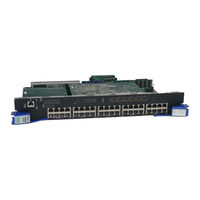
Enterasys Matrix DFE-Gold 4G4282-41 Hardware Installation Manual (78 pages)
DFE-Gold Series
Brand:
Enterasys
| Category:
Switch
| Size: 1 MB
Table of Contents
Industry Canada Notice
4
Product Safety
4
Regulatory Compliance Information
4
Seguridad del Producto
4
Electromagnetic Compatibility (EMC)
5
Elektro- Magnetische Kompatibilität ( EMC )
5
Hazardous Substances
5
BSMI EMC Statement - Taiwan
7
Safety Information
7
VCCI Notice
7
Declaration of Conformity
8
Table of Contents
13
About this Guide
17
Important Notice
17
Module
17
Who Should Use this Guide
17
How to Use this Guide
18
Related Documents
18
Conventions Used in this Guide
19
Getting Help
20
Important Notice
21
Chapter 1: Introduction
22
Overview of DFE-Gold Series Capabilities
22
The DFE-Gold Modules
23
4G4202-60 and 4G4282-41 DFE-Gold Modules
24
Connectivity
25
Management
25
Switch Configuration Using Webview
25
Switch Configuration Using CLI Commands
25
Secure Networks Policy Support
26
Standards Compatibility
26
LANVIEW Diagnostic Leds
26
Chapter 2: Network Requirements
27
Link Aggregation
27
10BASE-T Network
28
100BASE-TX Network
28
Installation
29
Chapter 3 : Installation
30
Installation Site Requirement
30
Unpacking the DFE-Gold Module
30
Installing Optional Network Expansion Module (NEM)
31
DFE Module Placement and Installation Rules
31
Examples, Slot Numbers and Module Placement in Matrix E7 or N7
32
Installing Module into a Chassis
33
Preparation
34
Installing Module into Matrix E7 or N7 Chassis
34
Installing Module into Matrix E7 or Matrix N7 Chassis (E7 Shown)
36
Installing Module into Matrix N3, N1, or N5 Chassis (N3 Shown)
37
Installing Module into Matrix N3, N1, or N5 Chassis (Matrix N3 Shown)
38
Connecting to the Network
39
Connecting UTP Cables to 4G4202-60 or 4G4282-41
39
Connecting a Twisted Pair Segment to the DFE-Gold Module
40
Four-Wire Crossover Cable RJ45 Pinouts, Connections between Hub Devices
41
Four-Wire Straight-Through Cable RJ45 Pinouts, Connections between Switches and End User Devices
41
Eight-Wire Crossover Cable RJ45 Pinouts, Connections between Hub Devices
42
Eight-Wire Straight-Through Cable RJ45 Pinouts, Connections between Switches and End User Devices
42
Connecting to COM Port for Local Management
43
What Is Needed
43
Connecting to an IBM PC or Compatible Device
44
Connecting to a VT Series Terminal
45
Connecting an IBM PC or Compatible
45
Connecting a VT Series Terminal
46
Connecting to a Modem
47
Connecting to a Modem
48
Adapter Wiring and Signal Assignments
49
Completing the Installation
50
Completing the Installation of a New System
50
Completing the Installation of a DFE-Gold Module in an Existing System
52
Matrix DFE Startup Screen Example (N7 Chassis)
52
Logging in with an Administratively-Configured User Account
53
Chapter 4: Troubleshooting
55
Using LANVIEW
55
About the Management (MGMT) LED
55
Viewing the Receive and Transmit Activity
56
LANVIEW Leds
56
LANVIEW Leds
57
Troubleshooting Checklist
59
Overview of DFE-Gold Module Shutdown Procedure
61
OFFLINE/RESET Switch
61
Recommended Shutdown Procedure Using OFFLINE/RESET Switch
62
Last Resort Shutdown Procedure Using OFFLINE/RESET Switch
62
A-1 Specifications
63
Appendix A: Specifications
63
DFE-Gold Module Specifications
63
COM Port Pinout Assignments
65
Regulatory Compliance
65
COM Port Pin Assignments
65
Compliance Standards
65
Chapter B: Mode Switch Bank Settings and Optional Installations
67
Required Tools
67
Setting the Mode Switches
68
Memory Locations and Replacement Procedures
69
Location of DRAM SIMM and DIMM Memory Modules
69
Mode Switch Location on 4G4202-60 and 4G4282-41
69
Memory Module Locations on the 4G4202-60
70
Memory Module Locations on the 4G4282-41
70
DIMM Replacement Procedure (4G4282-41
71
Removing NEM and DIMM Connector Location on 4G4282-41
72
Removing the Existing DIMM from 4G4282-41
72
Installing the DIMM on 4G4282-41
73
DRAM SIMM Replacement Procedure for 4G4202-60 or 4G4282-41
74
Removing the DRAM SIMM
74
Removing Existing DRAM SIMM from 4G4202-60 or 4G4282-41
74
Installing the DRAM SIMM
75
Advertisement
Advertisement
Related Products
Enterasys Matrix DFE-Gold 4G4202-60
Enterasys Enterasys Gold Distributed Forwarding Engine 4G4282-49
Enterasys 4G4282-49 DFE-Gold Series
Enterasys 4G4202-72 DFE-Gold Series
Enterasys Enterasys Gold Distributed Forwarding Engine 4H4285-49
Enterasys DFE-Gold 4H4203-72
Enterasys DFE-Gold 4H4282-49
Enterasys DFE-Gold 4H4283-49
Enterasys Enterasys Gold Distributed Forwarding Engine 4H4284-49
Enterasys Enterasys Gold Distributed Forwarding Engine 4H4202-72
Enterasys Categories
Switch
Network Router
Network Hardware
Wireless Access Point
Software
More Enterasys Manuals
Login
Sign In
OR
Sign in with Facebook
Sign in with Google
Upload manual
Upload from disk
Upload from URL