Sign In
Upload
Manuals
Brands
Enterasys Manuals
Switch
Matrix 7G4280-19
Enterasys Matrix 7G4280-19 Manuals
Manuals and User Guides for Enterasys Matrix 7G4280-19. We have
2
Enterasys Matrix 7G4280-19 manuals available for free PDF download: Hardware Installation Manual, Specifications
Enterasys Matrix 7G4280-19 Hardware Installation Manual (92 pages)
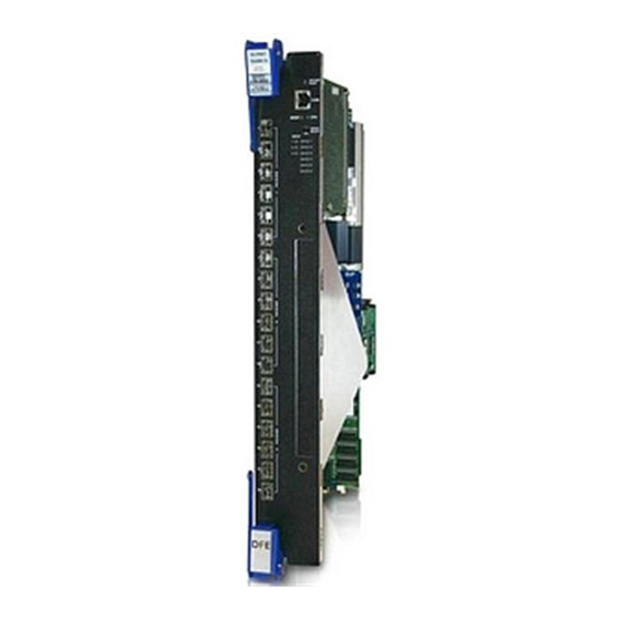
DFE-Platinum Series
Brand:
Enterasys
| Category:
Switch
| Size: 1.81 MB
Table of Contents
Industry Canada Notice
4
Product Safety
4
Regulatory Compliance Information
4
Hazardous Substances
5
Declaration of Conformity
8
Safety Information
8
Table of Contents
13
About this Guide
17
Important Notice
17
How to Use this Guide
18
Who Should Use this Guide
18
Conventions Used in this Guide
19
Related Documents
19
Getting Help
20
Chapter 1 : Introduction
21
Overview of DFE-Platinum Series Module Capabilities
21
DFE Module and Interface Options
22
G4280-19
22
7G4280-19 DFE-Platinum Module
23
Network Expansion Module Options
24
Connectivity
24
G4280-19
24
Mini-Gbics
24
Management
24
Switch Configuration Using Webview
25
Switch Configuration Using CLI Commands
25
Secure Networks Policy Support
25
Standards Compatibility
26
LANVIEW Diagnostic Leds
26
Chapter 2: Network Requirements
29
Link Aggregation
29
Module Placement in a Matrix E7 Chassis
30
1000BASE-SX/LX/ELX Network
30
1000BASE-T Network
30
Chapter 3: Installation
31
Required Tools
32
Unpacking the DFE Module
32
Installing Optional Network Expansion Module (NEM)
32
Contents of 7G4280-19 Module Carton
32
Installing Optional Mini-Gbics
33
Mini-GBIC with MT-RJ Connector
34
Mini-GBIC with LC Connector
35
Mini-GBIC with RJ45 Connector
35
Backplane Connections and Installation Rules
37
FTM1 and FTM2 Connectivity
37
Module Placement and Rules
37
Examples, Module Placement in Matrix E7 Chassis
38
Installing 7G4280-19 in Matrix E7 or Matrix N7 Chassis
40
Preparation
40
Installation
41
Installing Module into Matrix E7 or N7 Chassis (Matrix E7 Shown)
42
Installing 7G4280-19 in Matrix N3, N5, or N1 Chassis
43
Connecting to the Network
44
Installing Module into N3, N5, or N1 Chassis (N3 Shown)
44
Monitoring and Verifying Front-Panel Port Connections
45
Monitoring and Verifying NEM Port Connections
45
Connecting a Twisted Pair Segment to the 7G4280-19
45
Connecting UTP Cables to Mini-Gbics
46
Cable Connection to RJ45 Copper Connector
47
Four-Wire Straight-Through Cable RJ45 Pinouts, Connections between Switches and End-User Devices
49
Eight-Wire Crossover Cable RJ45 Pinouts, Connections between Hub Devices
49
Eight-Wire Straight-Through Cable RJ45 Pinouts, Connections between Switches and End-User Devices
50
Connecting Fiber-Optic Cables to Mini-Gbics
51
Cable Connection to MT-RJ Fiber-Optic Connectors
52
Cable Connection to LC Fiber-Optic Connectors
53
Connecting to COM Port for Local Management
54
What Is Needed
54
Connecting to an IBM PC or Compatible Device
55
Connecting to a VT Series Terminal
56
Connecting an IBM PC or Compatible
56
Connecting to a Modem
57
Connecting a VT Series Terminal
57
Connecting to a Modem
58
Adapter Wiring and Signal Assignments
59
Completing the Installation
60
Completing the Installation of a New System
60
Completing the Installation of a DFE Module in an Existing System
62
Matrix DFE Startup Screen Example (N7 Chassis)
62
Chapter 4: Troubleshooting
65
Using LANVIEW Diagnostic Leds
65
Troubleshooting Checklist
65
LANVIEW Leds
66
LANVIEW Leds
67
Troubleshooting Checklist
69
Overview of DFE Module Shutdown Procedure
71
OFFLINE/RESET Switch
71
Recommended Shutdown Procedure Using OFFLINE/RESET Switch
72
Last Resort Shutdown Procedure Using OFFLINE/RESET Switch
72
Appendix A: Specifications
73
7G4280-19 Specifications
73
Mini-GBIC Input/Output Specifications
74
Mini-GBIC Input/Output Port Specifications
74
Gigabit Ethernet Specifications
75
MGBIC-LC01/MGBIC-MT01 Specifications (1000BASE-SX
75
MGBIC-LC01/MGBIC-MT01 Optical Specifications
75
MGBIC-LC01/MGBIC-MT01 Operating Range
75
MGBIC-LC03 Specifications (1000BASE-SX
76
MGBIC-LC03 Optical Specifications
76
MGBIC-LC03 Operating Range
76
MGBIC-LC09 Specifications (1000BASE-LX
77
MGBIC-08 Specifications (1000BASE-ELX
77
MGBIC-LC09 Optical Specifications
77
MGBIC-LC09 Operating Range
77
MGBIC-08 Optical Specifications
77
MGBIC-08 Operating Range
77
MGBIC-02 Specifications (1000BASE-T
78
COM Port Pinout Assignments
78
MGBIC-02 Specifications
78
COM Port Pin Assignments
78
Regulatory Compliance
79
Compliance Standards
79
Appendix B: Mode Switch Settings and Installing Options
81
Required Tools
81
Setting the Mode Switches
82
Memory Locations
83
Mode Switch Location
83
Memory Replacement Procedures
84
DIMM Replacement Procedure
84
DIMM and DRAM SIMM Locations
84
Removing the Optional Network Expansion Module (NEM
85
Removing the Existing DIMM
86
Installing the DIMM
86
DRAM SIMM Replacement Procedure
87
Removing the Existing DRAM SIMM
88
Installing the DRAM SIMM
89
Advertisement
Enterasys Matrix 7G4280-19 Specifications (5 pages)
N-Series Platinum DFE 10GE Modular L2/L3/L4 Switch for Edge-to-Core and Data Center
Brand:
Enterasys
| Category:
Switch
| Size: 0.38 MB
Table of Contents
Product Overview
1
Standards and Protocols
2
Class of Service
3
Network Management
3
Specifications
4
Ordering Information
4
Service and Support
5
Advertisement
Related Products
Enterasys Matrix 7G4270-09
Enterasys Matrix 7G4270-10
Enterasys Matrix 7G4270-12
Enterasys Matrix 7G4202-72
Enterasys Matrix 7G4282-49
Enterasys Matrix 7G4282-41
Enterasys Matrix DFE-Platinum 7G4202-60
Enterasys Matrix 7GR4270-12
Enterasys Matrix 7H4202-72
Enterasys Matrix 7H4284-49
Enterasys Categories
Switch
Network Router
Network Hardware
Wireless Access Point
Software
More Enterasys Manuals
Login
Sign In
OR
Sign in with Facebook
Sign in with Google
Upload manual
Upload from disk
Upload from URL