Sign In
Upload
Manuals
Brands
Edwards Manuals
Water Pump
STP-301 Series
User Manuals: Edwards STP-301 Series Turbo Pump
Manuals and User Guides for Edwards STP-301 Series Turbo Pump. We have
5
Edwards STP-301 Series Turbo Pump manuals available for free PDF download: Instruction Manual
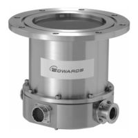
Edwards STP-301 Series Instruction Manual (121 pages)
STP Series Turbomolecular Pumps
Brand:
Edwards
| Category:
Water Pump
| Size: 1 MB
Table of Contents
Safety Precautions
2
Applied Standards
6
Introduction
6
Limited Warranty
8
Table of Contents
9
1 Precautions for Safe Operation of the STP Pump
14
Usable Gases
14
Precautions on Maintenance and Inspection
14
Labels
15
2 Operation Principle of the STP Pump
18
Figure 2.1 Cross Sectional View of the STP Pump
19
3 Unpacking
20
Unpacking the STP Pump and the STP Control Unit
20
Accessories
20
Table 3.1 Accessories
20
Table 3.2 Accessories for Chemical Specific Pump (Type C)
20
4 Installation of the STP Pump
22
Name and Function of each Part
22
Figure 4.1 Configuration of the STP Pump
23
Precautions before Installation
24
Operating Environment
24
Installation Area
25
Bench
25
How to Install the STP Pump
26
Figure 4.2 Installation of the STP Pump to the Vacuum Equipment
26
Cleaning the Seal
27
Figure 4.3 STP Pump Installation Positions
28
Figure 4.4 Positions of the Outlet Port on the Horizontally or Slanted Installed STP Pump
28
STP Pump Installation Positions
28
How to Secure the STP Pump
29
Table 4.1 Tightening Torque of Bolt
29
Figure 4.5 Example of Securing the STP Pump (When Securing the Inlet Port with Bolts)
30
Table 4.2 Maximum Torque Predicted and Recommended Securing Bolt for Inlet Port Flange
30
Figure 4.6 Example of Securing the STP Pump (When Securing the Inlet Port Flange with Claw Clamps)
31
Table 4.3 Number of Claw Clamps by Size of Flange
31
Figure 4.7 Example of Securing the STP Pump (When Installing the Damper in the Inlet Port Flange)
32
Vacuum Piping
33
Connecting the Ground Cable
34
Connecting the Purge Port (for the Chemical Specific Pump, Type C)
35
Figure 4.8 Connecting the Purge Port
35
5 Baking, Cooling the STP Pump and Gas Pumping
36
Baking the STP Pump
36
Attaching a Baking Heater
36
Cooling the STP Pump
37
Water Cooling Method
37
Air Cooling Method
38
Gas Pumping
39
How to Introduce a Purge Gas [For Chemical Specific Pump (Type C)]
39
Figure 5.1 Attaching Positions of the Cooling Unit and Baking Heater
40
6 Installation of the STP Control Unit
42
Name and Function of each Part
42
Front Panel
42
Figure 6.1 STP Control Unit Front Panel
43
Rear Panel
44
Figure 6.2 STP Control Unit Rear Panel
45
Top Panel
46
Figure 6.3 STP Control Unit Top Panel
46
Side Panel (Left)
47
Figure 6.4 STP Control Unit Side Panel (Left)
47
Operating Environment
48
Insulation Test
48
Precautions before Installation
48
Installation Area
49
Figure 6.5 Peripheral Spaces of the STP Control Unit
49
Attaching the STP Control Unit Front Panel to a Rack
50
Figure 6.6 Example of Securing the STP Control Unit
50
Cable Connection
51
Name and Dimensions of each Cable
51
Figure 6.7 External Dimensions of Ground Cable
51
Figure 6.8 External Dimensions of STP Connection Cable
51
Figure 6.9 External Dimensions of STP Connection Cable
52
How to Connect the Cables
53
Table 6.1 Connecting the Power Cable
54
Figure 6.10 Connecting Method of the AC Power Cable
54
Figure 6.11 How to Secure the Power Cable
55
Connecting to Semiconductor Equipment
56
Connecting to Power
56
Emergency off Circuit (EMO Circuit)
56
7 How to Start/Stop the STP Pump
58
Before Starting
58
Start Procedures
59
Stop Procedures
59
Manual Operation
60
Powering on
60
Starting the STP Pump
60
Stopping the STP Pump
60
Starting the STP Pump after Stopping
61
Powering off
61
Starting the STP Pump after a Safety Function Operates
61
Remote Operation (I/O TB2)
62
Powering on
62
Starting/Stopping the STP Pump
62
Starting the STP Pump after Stopping
62
Table 7.1 Starting/Stopping the STP Pump During Remote Operation (I/O TB2)
62
Powering off
63
Starting the STP Pump after a Safety Function Operates
63
Table 7.2 Reset Operation During Remote Operation (I/O TB2)
63
Remote Operation (CON4: Optional Accessory)
64
Powering on
64
Starting/Stopping the STP Pump
64
Starting the STP Pump after Stopping
64
Table 7.3 Starting/Stopping the STP Pump During Remote Operation (CON4)
64
Powering off
65
Starting the STP Pump after a Safety Function Operates
65
Table 7.4 Reset Operation During Remote Operation (CON4)
65
Figure 7.1 STP Pump Operation Procedures
66
8 Remote Input/Output Signal Terminal Blocks
68
I/O TB1 Terminal Block
68
Table 8.1 I/O TB1 Terminal Block
68
Figure 8.1 I/O TB1 Remote Output Signal Terminal Block
70
Table 8.2 Rated Contacts for Relays CR1, 3, 5, 7, and 8
71
I/O TB2 Terminal Block
72
Table 8.4 I/O TB2 Terminal Block
72
Figure 8.2 I/O TB2 Remote Input Signal Terminal Block
73
CON4 Connector (Optional Accessory)
74
Remote Input Signals
74
Table 8.5 CON4 Connector (Remote Input Signal)
74
Figure 8.3 CON4 Remote Input Signal Connector
75
Table 8.6 Rated Coils for Relays CR1, 2 and 3
75
Remote Output Signals
76
Table 8.7 con 4 Connector (Remote Output Signal)
76
Figure 8.4 CON4 Remote Output Signal Connector
77
Remote Cables (Optional Accessories)
78
Table 8.9 Remote Cable Connections (Single-Side Connector Type)
78
9 Adjustment Method
80
Tuning
80
Tuning Method
80
Figure 9.1 Tuning Procedures
81
Setting the Rated Speed
82
When Setting DSW-B No. 1 to on under Power-ON State
82
When Setting DSW-B No. 1 to on before Powering on
83
Figure 9.2 LCD Message in Rated Speed Setting Mode
84
10 Safety Functions
86
Power Failure
86
Table 10.1 States of Lamps and REMOTE Output Signals at Power Failure
87
Table 10.2 Operations of the STP Pump after Power Recovery
87
Abnormal State of Magnetic Bearing
88
Excessive Vibration
88
Motor Driver Overload
88
Overheating Inside the STP Pump
88
Overheating Inside the STP Control Unit
88
Overspeed
88
Table 10.3 Safety Functions
89
11 Troubleshooting, Maintenance and Inspection
92
Troubleshooting Immediately after an Abnormality/Error Occurs
92
In Case of a Power Failure
92
In Other Cases
92
When Error Message Is Displayed
93
Error Messages
93
Table 11.1 Error Messages
94
Displaying Past Abnormalities/Errors and Accumulated Running-Time
96
Abnormalities When Powering on
98
Abnormalities When Performing the STP Pump Start Operation
98
Table 11.2 Troubleshooting after Powering on
98
Table 11.3 Troubleshooting When Performing the STP Pump Start Operation
98
Other Abnormalities
99
Table 11.4 Troubleshooting While the STP Pump Is Rotating
99
Maintenance and Inspection
100
Inspecting the Air Cooling Fan
100
Replacing the Fuses
101
Table 11.5 Recommended Spare Parts
101
Cleaning and Decontamination
102
Inspecting for Deposit
102
Table 11.6 Cleaning and Decontamination
102
Overhaul
103
Transporting for Repair or Overhaul
104
12 Storage and Disposal
106
Storage of the STP Pump
106
Storage of the STP Control Unit
106
Disposal
107
13 Specifications and Accessories
108
Specifications of the STP Pump
108
Table 13.1 Specifications of the STP Pump
108
Figure 13.1 External Appearance of the STP Pump [Without Anti-Corrosion Treatment]
109
Figure 13.2 External Appearance of the STP Pump [Chemical Specific Type C]
110
Figure 13.3 Label Affixing Position for the STP Pump
111
Specifications of the STP Control Unit
112
Table 13.2 Specifications of the STP Control Unit
112
Figure 13.4 External Appearance of the the STP Control Unit
114
Figure 13.5 Label Affixing Positions for the STP Control Unit
115
Unit Conversion Table
116
Advertisement
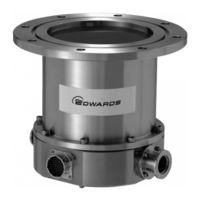
Edwards STP-301 Series Instruction Manual (118 pages)
Turbomolecular Pumps
Brand:
Edwards
| Category:
Water Pump
| Size: 1 MB
Table of Contents
Limited Warranty
9
Table of Contents
10
Precautions for Safe Operation of the STP Pump
15
Usable Gases
15
Precautions on Maintenance and Inspection
15
Labels
16
Operation Principle of the STP Pump
19
Figure 2.1 Cross Sectional View of the STP Pump
20
Unpacking
21
Unpacking the STP Pump and the STP Control Unit
21
Accessories
21
Table 3.1 Accessories
21
Table 3.2 Accessories for Chemical Specific Pump (Type C)
21
Installation of the STP Pump
23
Name and Function of each Part
23
Figure 4.1 Configuration of the STP Pump
24
Precautions before Installation
25
Operating Environment
25
Installation Area
26
Bench
26
How to Install the STP Pump
27
Figure 4.2 Installation of the STP Pump to the Vacuum Equipment
27
Cleaning the Seal
28
STP Pump Installation Positions
29
Figure 4.3 STP Pump Installation Positions
29
Figure 4.4 Positions of the Outlet Port on the Horizontally or Slanted Installed STP Pump
29
How to Secure the STP Pump
30
Table 4.1 Tightening Torque of Bolt
30
Table 4.2 Maximum Torque Predicted and Recommended Securing Bolt for Inlet Port Flange
31
Figure 4.5 Example of Securing the STP Pump (When Securing the Inlet Port with Bolts)
31
Table 4.3 Number of Claw Clamps by Size of Flange
32
Figure 4.6 Example of Securing the STP Pump (When Securing the Inlet Port Flange with Claw Clamps)
32
Figure 4.7 Example of Securing the STP Pump (When Installing the Damper in the Inlet Port Flange)
33
Vacuum Piping
34
Connecting the Ground Cable
35
Connecting the Purge Port (for the Chemical Specific Pump, Type C)
36
Figure 4.8 Connecting the Purge Port
36
Baking, Cooling the STP Pump and Gas Pumping
37
Baking the STP Pump
37
Attaching a Baking Heater
37
Cooling the STP Pump
38
Water Cooling Method
38
Air Cooling Method
39
Gas Pumping
40
How to Introduce a Purge Gas [For Chemical Specific Pump (Type C)]
40
Figure 5.1 Attaching Positions of the Cooling Unit and Baking Heater
41
Installation of the STP Control Unit
43
Name and Function of each Part
43
Front Panel
43
Figure 6.1 STP Control Unit Front Panel
44
Rear Panel
45
Figure 6.2 STP Control Unit Rear Panel
46
Top Panel
47
Figure 6.3 STP Control Unit Top Panel
47
Side Panel (Left)
48
Figure 6.4 STP Control Unit Side Panel (Left)
48
Precautions before Installation
49
Operating Environment
49
Insulation Test
49
Installation Area
50
Figure 6.5 Peripheral Spaces of the STP Control Unit
50
Attaching the STP Control Unit Front Panel to a Rack
51
Figure 6.6 Example of Securing the STP Control Unit
51
Cable Connection
52
Name and Dimensions of each Cable
52
Figure 6.7 External Dimensions of Ground Cable
52
Figure 6.8 External Dimensions of STP Connection Cable
52
Figure 6.9 External Dimensions of STP Connection Cable
53
How to Connect the Cables
54
Table 6.1 Connecting the Power Cable
55
Figure 6.10 Connecting Method of the AC Power Cable
55
Figure 6.11 How to Secure the Power Cable
56
Connecting to Semiconductor Equipment
57
Connecting to Power
57
Emergency off Circuit (EMO Circuit)
57
How to Start/Stop the STP Pump
59
Before Starting
59
Start Procedures
60
Stop Procedures
60
Manual Operation
61
Powering on
61
Starting the STP Pump
61
Stopping the STP Pump
61
Starting the STP Pump after Stopping
62
Powering off
62
Starting the STP Pump after a Safety Function Operates
62
Remote Operation (I/O TB2)
63
Powering on
63
Starting/Stopping the STP Pump
63
Starting the STP Pump after Stopping
63
Table 7.1 Starting/Stopping the STP Pump During Remote Operation (I/O TB2)
63
Powering off
64
Starting the STP Pump after a Safety Function Operates
64
Table 7.2 Reset Operation During Remote Operation (I/O TB2)
64
Remote Operation (CON4: Optional Accessory)
65
Powering on
65
Starting/Stopping the STP Pump
65
Starting the STP Pump after Stopping
65
Table 7.3 Starting/Stopping the STP Pump During Remote Operation (CON4)
65
Powering off
66
Starting the STP Pump after a Safety Function Operates
66
Table 7.4 Reset Operation During Remote Operation (CON4)
66
Figure 7.1 STP Pump Operation Procedures
67
Remote Input/Output Signal Terminal Blocks
69
I/O TB1 Terminal Block
69
Table 8.1 I/O TB1 Terminal Block
69
Figure 8.1 I/O TB1 Remote Output Signal Terminal Block
71
I/O TB2 Terminal Block
73
Table 8.4 I/O TB2 Terminal Block
73
Figure 8.2 I/O TB2 Remote Input Signal Terminal Block
74
CON4 Connector (Optional Accessory)
75
Remote Input Signals
75
Table 8.5 CON4 Connector (Remote Input Signal)
75
Figure 8.3 CON4 Remote Input Signal Connector
76
Remote Output Signals
77
Table 8.7 con 4 Connector (Remote Output Signal)
77
Figure 8.4 CON4 Remote Output Signal Connector
78
Remote Cables (Optional Accessories)
79
Table 8.9 Remote Cable Connections (Single-Side Connector Type)
79
Adjustment Method
81
Tuning
81
Tuning Method
81
Figure 9.1 Tuning Procedures
82
Setting the Rated Speed
83
When Setting DSW-B No. 1 to on under Power-ON State
83
When Setting DSW-B No. 1 to on before Powering on
84
Figure 9.2 LCD Message in Rated Speed Setting Mode
85
10 Safety Functions
87
Power Failure
87
Table 10.1 States of Lamps and REMOTE Output Signals at Power Failure
88
Table 10.2 Operations of the STP Pump after Power Recovery
88
Abnormal State of Magnetic Bearing
89
Excessive Vibration
89
Motor Driver Overload
89
Overheating Inside the STP Pump
89
Overheating Inside the STP Control Unit
89
Overspeed
89
11 Troubleshooting, Maintenance and Inspection
93
Troubleshooting Immediately after an Abnormality/Error Occurs
93
In Case of a Power Failure
93
In Other Cases
93
When Error Message Is Displayed
94
Error Messages
94
Table 11.1 Error Messages
95
Displaying Past Abnormalities/Errors and Accumulated Running-Time
97
Abnormalities When Powering on
99
Abnormalities When Performing the STP Pump Start Operation
99
Table 11.2 Troubleshooting after Powering on
99
Table 11.3 Troubleshooting When Performing the STP Pump Start Operation
99
Other Abnormalities
100
Table 11.4 Troubleshooting While the STP Pump Is Rotating
100
Maintenance and Inspection
101
Inspecting the Air Cooling Fan
101
Replacing the Fuses
102
Table 11.5 Recommended Spare Parts
102
Cleaning and Decontamination
103
Inspecting for Deposit
103
Table 11.6 Cleaning and Decontamination
103
Overhaul
104
Transporting for Repair or Overhaul
105
12 Storage and Disposal
107
Storage of the STP Pump
107
Storage of the STP Control Unit
107
Disposal
108
13 Specifications and Accessories
109
Specifications of the STP Pump
109
Table 13.1 Specifications of the STP Pump
109
Figure 13.1 External Appearance of the STP Pump [Without Anti-Corrosion Treatment]
110
Figure 13.2 External Appearance of the STP Pump [Chemical Specific Type C]
111
Figure 13.3 Label Affixing Position for the STP Pump
112
Specifications of the STP Control Unit
113
Table 13.2 Specifications of the STP Control Unit
113
Safety Functions
114
Figure 13.4 External Appearance of the the STP Control Unit
115
Figure 13.5 Label Affixing Positions for the STP Control Unit
116
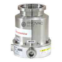
Edwards STP-301 Series Instruction Manual (122 pages)
Turbomolecular Pump
Brand:
Edwards
| Category:
Water Pump
| Size: 0 MB
Table of Contents
Limited Warranty
9
Table of Contents
11
1 Precautions for Safe Operation of the STP Pump
16
Usable Gases
16
Precautions on Maintenance and Inspection
16
Labels
17
2 Operation Principle of the STP Pump
20
Figure 2.1 Cross Sectional View of the STP Pump
21
3 Unpacking
22
Unpacking the STP Pump and the STP Control Unit
22
Accessories
22
4 Installation of the STP Pump
23
Name and Function of each Part
23
Figure 4.1 Configuration of the STP Pump
24
Precautions before Installation
25
Operating Environment
25
Installation Area
26
Bench
26
How to Install the STP Pump
28
Figure 4.2 Installation of the STP Pump to the Vacuum Equipment
28
Cleaning the Seal
29
Figure 4.3 STP Pump Installation Positions
30
STP Pump Installation Positions
30
How to Secure the STP Pump
31
Table 4.1 Tightening Torque of Bolt
31
Figure 4.6 Example of Securing the STP Pump (When Securing the Inlet Port Flange W Ith Claw Clamps)
33
Table 4.3 Number of Claw Clamps by Size of Flange
33
Vacuum Piping
35
Connecting the Ground Cable
36
Connecting the Purge Port (for the Chemical Specific Pump, Type C)
37
Figure 4.8 Connecting the Purge Port
37
5 Baking, Cooling the STP Pump and Gas Pumping
38
Baking the STP Pump
38
Attaching a Baking Heater
38
Cooling the STP Pump
39
Water Cooling Method
39
Air Cooling Method
40
Gas Suction
41
How to Introduce a Purge Gas [For Chemical Specific Pump (Type C)]
41
Figure 5.1 Attaching Positions of the Cooling Unit and Baking Heater
42
6 Installation of the STP Control Unit
43
Name and Function of each Part
43
Front Panel
43
Figure 6.1 STP Control Unit Front Panel
45
Rear Panel
46
Figure 6.2 STP Control Unit Rear Panel
47
Top Panel
48
Figure 6.3 STP Control Unit Top Panel
48
Side Panel (Left)
49
Figure 6.4 STP Control Unit Side Panel (Left)
49
Precautions before Installation
50
Operating Environment
50
Insulation Test
50
Installation Area
51
Attaching the STP Control Unit Front Panel to a Rack
52
Figure 6.6 Example of Securing the STP Control Unit
52
Cable Connection
53
Name and Dimensions of each Cable
53
Figure 6.9 External Dimensions of STP Connection Cable
54
How to Connect the Cables
55
Figure 6.10 How to Secure the Pow er Cable
57
Connecting to Semiconductor Equipment
58
Connecting to Pow er
58
Emergency off Circuit (EMO Circuit)
58
7 How to Start/Stop the STP Pump
59
Before Starting
59
Start Procedures
60
Stop Procedures
60
Manual Operation
61
Pow Ering on
61
Starting the STP Pump
61
Stopping the STP Pump
61
Starting the STP Pump after Stopping
63
Pow Ering off
63
Starting the STP Pump after a Safety Function Operates
63
Remote Operation (I/O TB2)
64
Pow Ering on
64
Starting/Stopping the STP Pump
64
Pow Ering off
64
Table 7.1 Starting/Stopping the STP Pump During Remote Operation (I/O TB2)
64
Starting the STP Pump after a Safety Function Operates
66
Table 7.2 Reset Operation During Remote Operation (I/O TB2)
66
Remote Operation (CON4: Optional Accessory)
68
Pow Ering on
68
Starting/Stopping the STP Pump
68
Table 7.3 Starting/Stopping the STP Pump During Remote Operation (CON4)
68
Starting the STP Pump after Stopping
69
Pow Ering off
69
Starting the STP Pump after a Safety Function Operates
69
Table 7.4 Reset Operation During Remote Operation (CON4)
69
Figure 7.1 STP Pump Operation Procedures
70
8 Remote Input/Output Signal Terminal Blocks
71
I/O TB1 Terminal Block
71
Table 8.1 I/O TB1 Terminal Block
71
Figure 8.1 I/O TB1 Remote Output Signal Terminal Block
73
I/O TB2 Terminal Block
75
Table 8.4 I/O TB2 Terminal Block
75
CON4 Connector (Optional Accessory)
78
Remote Input Signals
78
Table 8.5 CON4 Connector (Remote Input Signal)
78
Remote Output Signals
80
Table 8.7 con 4 Connector (Remote Output Signal)
80
Figure 8.4 CON4 Remote Output Signal Connector
82
Remote Cables (Optional Accessories)
83
9 Adjustment Method
84
Tuning
84
Tuning Method
84
Figure 9.1 Tuning Procedures
85
Setting the Rated Speed
86
When Setting DSW-B No. 1 to on under Pow Er-ON State
86
When Setting DSW-B No. 1 to on before Pow Ering on
87
10 Safety Functions
89
Pow er Failure
89
Abnormal State of Magnetic Bearing
91
Excessive Vibration
91
Motor Driver Overload
91
Overheating Inside the STP Pump
91
Overheating Inside the STP Control Unit
91
Overspeed
91
11 Troubleshooting, Maintenance and Inspection
95
Troubleshooting Immediately after an Abnormality/Error Occurs
95
In Case of a Pow er Failure
95
In Other Cases
95
When Error Message Is Displayed
96
Error Messages
96
Table 11.1 Error Messages
97
Displaying Past Abnormalities/Errors and Accumulated Running-Time
100
Abnormalities When Pow Ering on
102
Abnormalities When Performing the STP Pump Start Operation
102
Table 11.2 Troubleshooting after Pow Ering on
102
Table 11.3 Troubleshooting When Performing the STP Pump Start Operation
102
Other Abnormalities
103
Table 11.4 Troubleshooting While the STP Pump Is Rotating
103
Maintenance and Inspection
104
Inspecting the Air Cooling Fan
104
Replacing the Fuses
105
Table 11.5 Recommended Spare Parts
105
Cleaning and Decontamination
106
Inspecting for Deposit
106
Table 11.6 Cleaning and Decontamination
106
Overhaul
108
Transporting for Repair or Overhaul
109
12 Storage and Disposal
110
Storage of the STP Pump
110
Storage of the STP Control Unit
110
Disposal
111
13 Specifications and Accessories
112
Specifications of the STP Pump
112
Table 13.1 Specifications of the STP Pump
112
Figure 13.1 External Appearance of the STP Pump [W Ithout Anti-Corrosion Treatment] (Example: STP-301)
113
Figure 13.2 External Appearance of the STP Pump [Chemical Specific Type C] (Example: STP-301C)
114
Figure 13.3 Label Affixing Position for the STP Pump
115
Figure 13.4 Label Affixing Positions for the Optional Accessories
116
Specifications of the STP Control Unit
117
Figure 13.5 External Appearance of the the STP Control Unit
119
Figure 13.6 Label Affixing Positions for the STP Control Unit
120
Unit Conversion Table
121
Advertisement
Edwards STP-301 Series Instruction Manual (63 pages)
Turbomolecular pumps
Brand:
Edwards
| Category:
Water Pump
| Size: 1 MB
Table of Contents
Table of Contents
3
Introduction
7
Scope and Definitions
7
Electromagnetic Compatibility
8
Limited Warranty
8
Item Warranted
8
Disclaimer
9
Spare Parts
9
Precautions for Safe Operation of the STP Pump
10
Usable Gases
10
STP Pump Installation Warning Label
11
Hot Surface Warning Label
11
Maintenance and Inspection Precautions
11
Labels
11
Heavy Product Caution Label
12
Connector Caution Label
12
Caution Label
12
TMS Heater Caution Label
13
Operation Principle of the STP Pump
14
Temperature Management System
15
Name of the STP Pump
16
Installation of the Stp Pump
19
Precautions before Installation
19
Operating Environment
19
Installation Area
21
Bench
22
Example of Lifting the STP Pump
23
Unpacking
23
Unpacking the STP Pump
23
Example of Lifting the STP Pump (Horizontal Positioning)
24
How to Install the STP Pump
26
Installation of the STP Pump to the Vacuum Equipment
27
Cleaning the Seal
28
Positions of the Outlet Port on the Horizontally or Slanted Installed STP Pump
29
STP Pump Installation Positions
29
Secure the STP Pump
30
Precautions of Vacuum Piping
30
Vacuum Piping Method
31
Positions of the Cooling Water Port and Baking Heater
32
Connecting the Purge Port
32
Connecting the Water Cooling Pipe
32
Attaching a Baking Heater
33
Installation of the Air Cooling Unit
33
2.3.10 Installation of the TMS Unit
33
Installation of the Stp Control Unit
35
STP Control Unit
35
SCU-350 Series
35
Scu-800/801
36
Scu-800
36
Scu-801
36
Scu-1600/1601
37
Scu-1601
37
Cable Connection
38
STP Connection Cable
38
Power Cable
39
How to Connect the Cables
40
Operation
43
Before Starting the STP Pump
43
Tuning
43
Operation of Vacuum System
44
Pump Operation
44
LED Indication During Operation
44
Starting the STP Pump after a Safety Function Operates
45
Gas Pumping, Cooling and Baking the STP Pump
45
Gas Pumping
45
How to Introduce a Purge Gas
46
Cooling the STP Pump
46
Water-Cooling Method
46
Air-Cooling Method
47
Baking the STP Pump
47
How to Use the TMS Unit
48
Parameter Set Mode
48
Starting/Stopping the TMS Unit
48
Temperature Control
48
Safety Functions
49
Power Failure
49
Operation after a Power Recovery
49
Abnormal State of Magnetic Bearing
50
Excessive Vibration
50
Motor Driver Overload
50
Overheating Inside the STP Pump
50
Overheating Inside the STP Control Unit
51
Overspeed
51
Abnormality/Error in the TMS Unit (for Use with the TMS Unit)
51
Failure of the Air-Cooling Fan (for SCU-800/801, SCU-1600/1601)
51
Maintenance and Inspection
53
Cleaning
54
Inspecting the Deposit
54
Maintenance
55
Recommended Overhaul Intervals
55
Standard Replacement Parts
55
Recommended Maintenance Intervals for Main Parts
56
Transporting for Repair or Overhaul
57
Storage and Disposal
59
Storage of the STP Pump
59
Disposal
60
Service, Spares and Accessories
61
Introduction
61
Service
61
Spares
61
Accessories
62
Edwards STP-301 Series Instruction Manual (23 pages)
Brand:
Edwards
| Category:
Water Pump
| Size: 1 MB
Table of Contents
Table of Contents
5
Technical Data
7
Applicable Pump Specifications
7
STP Pump Specifications
8
Condition for the Water-Cooling Unit
9
External Appearance of the STP Pump
10
External Appearance of STP-301/451 Series (Non-Corrosion Resistant Type)
10
External Appearance of STP-301/451 Series (Corrosion Resistant Type)
11
External Appearance of STP-301/451 Series (with Water Cooling Unit)
12
Label Affixing Positions
13
Label Affixing Positions for the STP Pump
13
Accessories
14
How to Secure the Stp Pump
15
Tightening Torque of Bolt
15
When Securing the Inlet Port with Bolts
16
Maximum Torque Predicted and Recommended Securing Bolt for Inlet Port Flange
16
Example of Securing the STP Pump (When Securing the Inlet Port with Bolts)
17
When Securing the Inlet Port Flange with Claw Clamps
18
Example of Securing the STP Pump (When Securing the Inlet Port Flange with Claw Clamps)
18
Number of Claw Clamps for Flange Size
18
When Installing the Damper in the Inlet Port Flange
19
Example of Securing the STP Pump (When Installing the Damper in the Inlet Port Flange)
19
Cooling the STP Pump
20
Installation of Air Cooling Unit
20
Air Cooling Unit and Baking Heater
21
Advertisement
Related Products
Edwards STP-301C
Edwards STP-301CB1
Edwards STP-301CVB3
Edwards STP-301H
Edwards STP-603 Series
Edwards STP-XA3203 Series
Edwards STP-XF1313 Series
Edwards STP-L301H
Edwards STP-iXA3307-HV Series
Edwards STP-XF1303BV135
Edwards Categories
Water Pump
Control Unit
Industrial Equipment
Measuring Instruments
Controller
More Edwards Manuals
Login
Sign In
OR
Sign in with Facebook
Sign in with Google
Upload manual
Upload from disk
Upload from URL