Sign In
Upload
Manuals
Brands
Eaton Manuals
UPS
CA22106060000R6
Eaton CA22106060000R6 Manuals
Manuals and User Guides for Eaton CA22106060000R6. We have
1
Eaton CA22106060000R6 manual available for free PDF download: Installation And Operation Manual
Eaton CA22106060000R6 Installation And Operation Manual (172 pages)
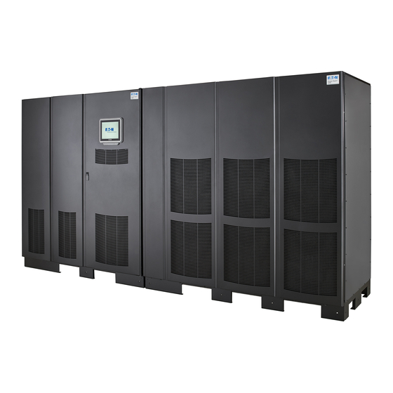
High Performance 300 kVA, 300 kW For use with Single UPM (200–300 kVA) and Plus 1 (200–300 kVA) UPS Models
Brand:
Eaton
| Category:
UPS
| Size: 3 MB
Table of Contents
Table of Contents
5
Introduction
11
Single UPM Configuration
11
Plus 1 Configuration
11
Figure 1-1. Single UPM and Plus 1 Configurations
12
UPS Standard Features
13
Installation Features
13
Control Panel
13
Customer Interface
13
Advanced Battery Management
13
Power Management Software
13
Options and Accessories
14
Integrated Battery Cabinets
14
Field Installed UPM
14
Sync Control
14
Single-Feed Kit
14
Distributed Bypass System
14
Input Output Module Configuration
15
Continuous Static Switch
15
Inherent Redundancy
15
Energy Saver and High Alert Modes
15
Variable Module Management System and High Alert Modes
16
Monitoring and Communication
16
Battery System
17
Using this Manual
18
Conventions Used in this Manual
18
Symbols, Controls, and Indicators
19
For more Information
20
Getting Help
20
Safety Warnings
21
Section I - Installation
25
UPS Installation Plan and Unpacking
27
Creating an Installation Plan
27
Preparing the Site
27
Environmental Considerations
27
Figure 3-1. ISBM with 1 UPM (Single UPM Configuration) Dimensions
30
Figure 3-2. ISBM with Two Upms (Two UPM Configuration) Dimensions
31
Figure 3-3. ISBM with 1 UPM + 1 FI-UPM (Plus 1 Configuration) Dimensions
32
UPS System Power Wiring Preparation
33
Distributed Bypass Power Wiring Preparation
41
Inspecting and Unpacking the UPS Cabinets
42
Figure 3-4. Single UPM Configuration as Shipped on Pallet (ISBM and UPM)
44
UPS System Installation
45
Preliminary Installation Information
45
Unloading the ISBM with UPM Section from the Pallet
45
Figure 4-1. Removing the ISBM Section Left Side Shipping Bracket
47
Figure 4-2. Removing the ISBM Section Right Side Shipping Bracket
48
Field Installed UPM Installation
49
Battery System Installation
49
Figure 4-4. ISBM and UPM Section Debris Shields
51
Figure 4-5. ISBM and UPM Section Conduit and Wire Entry Locations
52
Figure 4-6. ISBM Section Power Terminal Locations
54
Figure 4-7. ISBM Section Power Terminal Detail - Section AA
55
Figure 4-8. ISBM Section Power Terminal Detail BB - Common Battery
57
Figure 4-9. ISBM Section Interface Terminal Locations
59
Figure 4-10. Interface Terminal Detail
61
Figure 4-11. Typical Alarm Relay Connection
61
Figure 4-12. Terminal Blocks TB1, TB2, and TB3 Connector Assignments
62
Figure 4-13. Typical Battery Interface Connection - Common Battery System
64
Figure 4-14. Typical Battery Interface Connection - Separate Battery System
64
Figure 4-15. X-Slot Communication Bays
65
Figure 4-16. Remote EPO Switch Dimensions
66
Figure 4-17. REPO Switch
67
Figure 4-18. Normally-Open REPO Switch Wiring
68
Figure 4-19. Normally-Closed REPO Switch Wiring
69
Figure 4-20. Normally-Closed and Normally-Open REPO Switch Wiring
69
Figure 5-1. Hot Sync CAN Bridge Card
74
Figure 5-2. Hot Sync CAN Bridge Card Connections
75
Figure 5-3. Distributed Bypass System CAN and Pull-Chain Simplified Interface Wiring
77
Figure 5-4. Distributed Bypass System UPS CAN Wiring Without Mobs
77
Figure 5-5. Distributed Bypass Pull-Chain Wiring Without Mobs
78
Figure 5-6. Distributed Bypass Pull-Chain Wiring with Mobs
79
Figure 5-7. Remote Monitor Panel II and Relay Interface Module II Terminal Locations
82
Figure 5-8. Remote Monitor Panel II, Relay Interface Module II, or Supervisory Contact Module II Wiring
82
Figure 5-9. J1, J2, J3, and J4 15-Pin D-Sub Connectors
84
Figure 5-10. Supervisory Contact Module II Terminal Location
85
Figure 5-11. Supervisory Contact Module II TB2
86
Figure 5-12. Remote Monitor Panel II Dimensions
87
Figure 5-13. Relay Interface Module II Dimensions
88
Figure 5-14. Supervisory Contact Module II Dimensions
89
Figure 6-1. Main Elements of the UPS System
93
Figure 6-2. Path of Current through the UPS in Online Mode
95
Figure 6-3. Path of Current through the UPS in Bypass Mode
98
Figure 6-4. Path of Current through the UPS in Battery Mode
99
Figure 6-5. One UPM, Rectifier Feed, Battery System, Dual-Feed Configuration, Continuous Static Switch
102
Figure 6-6. One UPM, Common Rectifier Feed, Common Battery, Dual-Feed Configuration, Continuous Static Switch, FI-UPM
103
Figure 6-7. One UPM, Common Rectifier Feed, Separate Battery, Dual-Feed Configuration, Continuous Static Switch, FI-UPM
104
Figure 6-8. Two UPM, Common Rectifier Feed, Common Battery, Dual-Feed Configuration, Continuous Static Switch
105
Advertisement
Advertisement
Related Products
Eaton C-6000FC
Eaton C-6000FCL
Eaton C-6000F
Eaton C-6000FL
Eaton C-10000FC
Eaton C-10000FCL
Eaton C-10000F
Eaton C-10000FL
Eaton CA04801001E
Eaton Cutler-Hammer CA03310002E
Eaton Categories
UPS
Circuit breakers
Switch
Industrial Equipment
Industrial Electrical
More Eaton Manuals
Login
Sign In
OR
Sign in with Facebook
Sign in with Google
Upload manual
Upload from disk
Upload from URL