Sign In
Upload
Manuals
Brands
Eaton Manuals
UPS
93E UPS
Eaton 93E UPS Manuals
Manuals and User Guides for Eaton 93E UPS. We have
1
Eaton 93E UPS manual available for free PDF download: Installation And Operation Manual
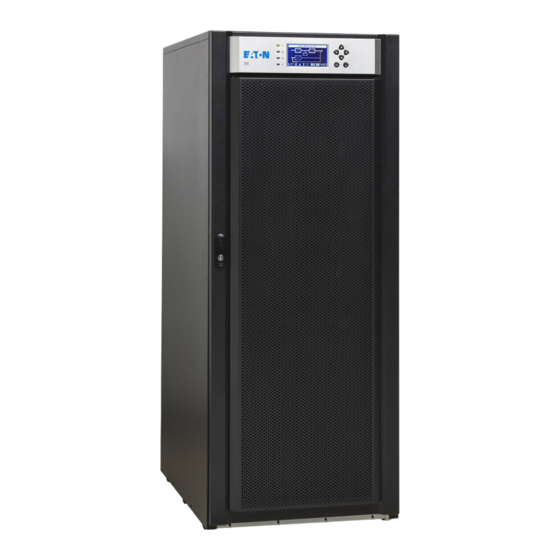
Eaton 93E UPS Installation And Operation Manual (110 pages)
15–80 kVA (380/400/415V)
Brand:
Eaton
| Category:
UPS
| Size: 6 MB
Table of Contents
Table of Contents
5
Introduction
13
Figure 1-1. Eaton 93E UPS (15-80 Kva)
13
UPS Standard Features
14
Installation Features
14
Control Panel
14
Customer Interface
14
High-Efficiency Mode
14
Advanced Battery Management
14
Maintenance Bypass
14
Options and Accessories
15
External Battery Cabinet
15
Parallel System
15
Monitoring and Communication
15
Dual Input
15
Battery System
16
Basic System Configurations
16
Using this Manual
16
Conventions Used in this Manual
16
Symbols, Controls, and Indicators
17
For more Information
17
Getting Help
17
Safety Warnings
19
Section 1-Installation
21
Ups Installation Plan and Unpacking
23
Creating an Installation Plan
23
Preparing the Site
23
Environmental and Installation Considerations
23
Table 3-1. UPS Cabinet Weights
24
Table 3-2. UPS Cabinet Clearances
25
Table 3-3. 93E Required Clearance
25
Table 3-4. Air Conditioning or Ventilation Requirements During Full Load Operation
26
Figure 3-1. UPS Cabinet Dimensions (93E 15-20 Kva Front and Right Side Views)
27
Figure 3-2. UPS Cabinet Dimensions (93E 30 Kva Front and Right Side Views)
28
Figure 3-3. UPS Cabinet Dimensions (93E 40 Kva Front and Right Side Views)
29
Figure 3-4. UPS Cabinet Dimensions (93E 60-80 Kva Front and Right Side Views)
30
Figure 3-5. UPS Cabinet Dimensions (Top and Bottom Views)
31
Figure 3-6. UPS Cabinet Centre of Gravity (93E 15-20 Kva)
32
Figure 3-7. UPS Cabinet Centre of Gravity (93E 30 Kva)
33
Figure 3-8. UPS Cabinet Centre of Gravity (93E 40 Kva)
34
Figure 3-9. UPS Cabinet Centre of Gravity (93E 60 Kva)
35
Figure 3-10. UPS Cabinet Centre of Gravity (93E 80 Kva)
36
UPS System Power Wiring Preparation
37
Table 3-5. Input /Output Ratings and External Wiring Requirements for the Eaton 93E 15-80 Kva
39
Table 3-6. UPS External Power Cable Terminations for the Eaton 93E 15-80 Kva
40
Table 3-7. Recommended Input Circuit Breaker Ratings
41
Table 3-8. Recommended Bypass and Output Circuit Breaker Ratings
41
Table 3-9. Recommended DC Input Circuit Breaker Rating
42
UPS System Interface Wiring Preparation
43
Inspecting and Unpacking the UPS Cabinets
44
Figure 3-11. UPS Cabinet as Shipped on Pallet
45
Ups System Installation
47
Preliminary Installation Information
47
Unloading the UPS Cabinet from the Pallet
47
Figure 4-1. Removing the Shipping Bracket
48
Figure 4-2. Attaching the Ramp to the Pallet
49
External Battery Cabinet Installation
50
External Power Wiring Installation
51
Figure 4-4. Power Terminal Locations 20-40 Kva
52
Figure 4-5. Power Terminal Locations 60-80 Kva
53
Installing Interface Connections
54
Installing Building Alarm Connections
54
Figure 4-6. Interface Terminal Locations
54
Figure 4-7. Interface Terminal Detail (Terminal Cover Removed)
55
Figure 4-8. Building Alarm Terminal Block Connector Assignments
55
Table 4-1. Building Alarm Connections
55
Figure 4-9. Interface Wiring Access
56
Installing Parallel Pull Chain and CAN Control Wiring and Connections
57
Figure 4-10. Pull Chain Terminal Block Connector Assignments
57
Table 4-2. Pull Chain Connections
57
Installing Mini-Slot Interface Connections
58
Figure 4-11. Parallel UPS Control Wiring
59
Figure 4-12. Parallel UPS System Connections
59
Installing a REPO Switch
60
Table 4-3. REPO Connections
60
Figure 4-14. Normally-Open REPO Switch Wiring
61
Initial Startup
62
Completing the Installation Checklist
62
Figure 4-15. Normally-Closed REPO Switch Wiring
62
Internal Battery Installation
64
Section 2-Operation
67
Understanding Ups Operation
69
UPS System Overview
69
Figure 5-1. Main Elements of the UPS System
69
Single UPS
70
Modes
70
Standard Normal Mode
70
High-Efficiency Mode
71
Figure 5-2. Path of Current through the UPS in Standard Normal Mode
71
Bypass Mode
72
Battery Mode
73
Single UPS Unit System Oneline Configurations
74
Figure 5-5. UPS System Oneline (Dual Input)
75
Figure 5-6. UPS System Oneline (Single Input)
76
Ups Operating Instructions
77
UPS Controls and Indicators
77
Control Panel
77
Figure 6-1. UPS Controls and Indicators
77
Figure 6-2. UPS Switches
78
Using the Control Panel
79
Status Indicators
79
Figure 6-3. UPS Control Panel
79
Table 6-1. Status Indicators
79
System Events
80
Using the LCD and Pushbuttons
81
Figure 6-4. Parts of the LCD
81
Using the Menu
82
MIMIC Screen
82
Figure 6-5. Main Menu and MIMIC Screen
82
Table 6-2. Display Function Menu Map
82
Display Menu Operation
83
Table 6-3. Display Menu Operation
83
System Controls
85
Figure 6-6. Typical Initial Setup Screen
85
Figure 6-7. Typical System Control Screen
86
Table 6-4. Command Menu Operation
86
Table 6-5. Typical System Status Messages
86
Single UPS Operation
87
Starting the UPS in Standard Normal Mode (Default Mode)
87
Starting the UPS in Bypass Mode
88
Transfer from Normal to Bypass Mode
88
Transfer from Bypass to Normal Mode
89
Transfer from Standard Normal Mode to HE Mode
89
Transfer from HE Mode to Standard Normal Mode
89
Transfer from Internal Maintenance Bypass to Normal Mode
90
UPS and Critical Load Shutdown
91
Charger Control
91
Battery Test
92
Using the UPS LOAD off Command
92
Using the Remote Emergency Power-Off Switch
93
Multiple UPS Parallel Operation
94
Starting the Parallel UPS in Standard Normal Mode (Default Mode)
94
Starting the Parallel UPS in Bypass Mode
95
Transfer from Normal to Bypass Mode
96
Transfer from Bypass to Normal Mode
96
Single UPS Shutdown
97
Single UPS Restart
97
UPS and Critical Load Shutdown
98
Charger Control
98
Battery Test
99
Using the UPS LOAD off Command
99
Using the Remote Emergency Power-Off Switch
100
Communication
101
Mini-Slot Cards
101
Building Alarm Monitoring
101
Figure 7-1. Optional Mini-Slot Cards
101
Ups Maintenance
104
Performing Preventative Maintenance
104
DAILY Maintenance
104
MONTHLY Maintenance
104
PERIODIC Maintenance
105
ANNUAL Maintenance
105
BATTERY Maintenance
105
Figure 8-1. Air Filter Location
105
Installing Batteries
106
Recycling the Used Battery or UPS
106
Maintenance Training
106
Product Specifications
107
Model Numbers
107
Specifications
107
UPS Environmental
107
UPS Input
108
UPS Output
108
Advertisement
Advertisement
Related Products
Eaton 93E-400/300
Eaton 93E 60ITC
Eaton 93E 60IAC-D
Eaton 93E-30/20
Eaton 93E-30/30
Eaton 93E-40
Eaton 93E-60/40
Eaton 93E MK2
Eaton 93E60KMBSN
Eaton 93E-300/300
Eaton Categories
UPS
Circuit breakers
Switch
Industrial Equipment
Industrial Electrical
More Eaton Manuals
Login
Sign In
OR
Sign in with Facebook
Sign in with Google
Upload manual
Upload from disk
Upload from URL