Sign In
Upload
Manuals
Brands
Deif Manuals
Controller
AGC-4 Mk II
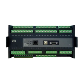
Deif AGC-4 Mk II Genset Controller Manuals
Manuals and User Guides for Deif AGC-4 Mk II Genset Controller. We have
3
Deif AGC-4 Mk II Genset Controller manuals available for free PDF download: Designers Handbook, Manual, Quick Start Manual
Deif AGC-4 Mk II Designers Handbook (196 pages)
Brand:
Deif
| Category:
Controller
| Size: 3 MB
Table of Contents
Table of Contents
2
1 Introduction
8
About the Designer's Handbook
8
General Purpose
8
Intended Users
8
Options
8
Parameter List
8
Glossary
8
Warnings, Legal Information and Safety
9
Warnings and Notes
9
Factory Settings
10
Automatic and Remote-Controlled Starts
10
Safety During Installation and Operation
10
Electrostatic Discharge Awareness
10
Legal Information and Disclaimer
10
2 Functions
11
Standard Functions
11
Operation Modes
11
Engine Control
11
Generator Protection (ANSI)
11
Busbar Protection (ANSI)
11
Display
11
M-Logic
12
AC Configuration
12
Three-Phase System
12
Split Phase System
13
Single Phase System
13
Nominal Settings
14
Switch between the Nominal Settings
14
Scaling
15
Applications
16
Applications and Genset Modes
16
AMF (no Back Synchronisation)
17
AMF (with Back Synchronisation)
17
Island Operation
18
Power Ramp
18
Q Ramp
20
Fixed Power/Base Load
20
Warm up Ramp
21
Peak Shaving
21
Load Takeover
23
Mains Power Export (Fixed Power to Mains)
24
Mains Power Transducer
25
Mains Reactive Power or Voltage Transducer
26
Running Modes
27
Semi-Auto Mode
27
Test Mode
27
Manual Mode
28
Block Mode
29
Single-Line Diagrams (no Power Management)
30
Automatic Mains Failure
30
Island Operation
31
Fixed Power/Base Load
31
Peak Shaving
31
Load Takeover
32
Mains Power Export
32
Multiple Gensets, Load Sharing (Hardware Option M12 Required)
33
Single-Line Diagrams with Power Management
33
Island Operation
33
Parallel to Mains
34
Multiple Mains
35
Automatic Transfer Switch
36
Energy Management System
37
Remote Maintenance
37
Flowcharts
37
Mode Shift
38
MB Open Sequence
39
Open Sequence
40
Stop Sequence
41
Start Sequence
42
MB Close Sequence
43
Close Sequence
44
Fixed Power
45
Load Takeover
46
Island Operation
47
Peak Shaving
48
Mains Power Export
49
Automatic Mains Failure
50
Test Sequence
51
Sequences
51
Start Sequence
52
Start Sequence Conditions
53
Running Feedback
54
Start-Up Overview
56
Start-Up Overview with Idle Run
58
Stop Sequence
58
Breaker Sequences
60
AMF Timers and Set Points
61
3 Standard Protections
64
General
64
Phase Sequence Error and Phase Rotation
65
Single DG Applications
65
Standard/Multiple Controller Applications
67
Loss of Excitation
69
Voltage-Dependent Over-Current
70
Unbalanced Current
71
Unbalanced Voltage
71
Over-Excitation
72
Voltage-Dependent (Restraint) Over-Current
72
Decision of Measurements
73
4 PID Regulator for Governor and AVR
75
Description of PID Controller
75
Controllers
75
Principle Drawing
76
Proportional Regulator
76
Speed Range
76
Dynamic Regulation Area
77
Integral Regulator
78
Derivative Regulator
78
Load Share Controller
79
Synchronising Controller
80
Relay Control
80
Relay Adjustments
81
Signal Length
82
Droop Mode
82
Principle and Setup
82
Voltage Droop Example
83
High Droop Setting
83
Low Droop Setting
84
Compensation for Isochronous Governors
84
5 Synchronisation
85
Synchronisation Principles
85
Dynamic Synchronisation
85
Close Signal
86
Load Picture after Synchronising
86
Adjustments
87
Static Synchronisation
88
Phase Controller
88
Close Signal
89
Load Picture after Synchronisation
89
Adjustments
89
Close before Excitation
90
Flowchart 1, GB Handling
91
Flowchart 2, TB Handling (Option G5)
92
Genset Start Actions
92
Breaker Sequence
93
Close before Excitation" Failure
94
Close before Excitation Without Voltage Control
94
Close before Excitation - Additional Control Parameters
94
Separate Synchronising Relay
96
Inhibit Conditions before Synchronising Mains Breaker
97
6 Additional Functions
99
Start Functions
99
Digital Feedbacks
99
Analogue Tacho Feedback
100
Oil Pressure
102
Double Starter
103
Running Output
103
Idle Running
104
Description
105
Examples
106
Configuration of Digital Input
106
Temperature-Dependent Idle Start-Up
107
Inhibit
108
Running Signal
108
Idle Speed Flowcharts
108
Analogue Load Sharing
110
Analogue Load Sharing Terminals
111
Working Principle
111
Island Ramp up with Load Steps
113
Freeze Power Ramp
113
Load Sharing Type
114
Load Sharing Modules
114
Selco T4800 Load Sharer
114
Cummins PCC
114
Ventilation
116
Max. Ventilation Alarm
116
Fan Logic
117
Fan Parameters
117
Input for Fan Control
117
Fan Start/Stop
118
Fan Output
119
Fan Start Delay
119
Fan Running Feedback
120
Fan Failure
120
Fan Priority (Running Hours)
121
Fan Priority Update
122
Derate Genset
122
Input Selection
123
Derate Parameters
123
Derate Characteristic
124
EIC Derate
124
Trip of Non-Essential Load (NEL)
125
Trip of NEL
125
Engine Heater
125
Engine Heater Alarm
126
Fuel Pump Logic
126
Fuel Fill Check
127
Fuel Tank Level and Volume
127
Service Menu
127
Service Timers
128
Command Timers
129
Oil Renewal Function
129
Breaker Functions
130
Breaker Types
130
Breaker Position Failure
131
Breaker Spring Load Time
131
Breaker Spring Load Time Principle
132
Racked out Breaker
132
Digital Mains Breaker Control
134
Overlap
134
Frequency- or Voltage-Dependent Droop
135
Power and Cos Phi Offsets
137
Power Offsets
137
Cos Phi Offsets
137
RRCR External Set Point Control
138
RRCR Configuration
138
Manual Governor and AVR Control
142
Manual Mode
142
Semi-Auto Mode
142
Auto and Test Mode
142
Fail Class
143
Engine Running
143
Engine Stopped
144
Fail Class Configuration
144
Alarm Inhibit
145
Run Status (6160)
146
Event Log
147
Logs
147
Display
147
Not in Auto
148
Connection TCP/IP and Network Parameters
148
M-Logic
150
Quick Setup
150
Parameter ID
151
Language Selection
151
Master Clock
151
Compensation Time
152
Summer/Winter Time
152
Access Lock
152
Battery Test
153
Input Configuration
154
Auto Configuration
155
Battery Asymmetry (6430 Batt. Asymmetry)
155
Internal Battery
157
Memory Backup
157
Switchboard Error
158
Block Swbd Error (Menu 6500)
158
Stop Swbd Error (Menu 6510)
159
Digital Inputs
159
Function Descriptions
160
Multi-Inputs
163
Input Function Selection
165
Wire Fail Detection
165
External Analogue Set Points
166
External Analogue Set Point Terminals
167
Other Sources of External Analogue Set Points
167
Outputs
167
Function Description
167
Limit Relay
168
Step-Up and Step-Down Transformer
169
Step-Up Transformer
169
Vector Group for Step-Up Transformer
170
Setup of Step-Up Transformer and Measurement Transformer
174
Vector Group for Step-Down Transformer
175
Setup of Step-Down Transformer and Measurement Transformer
176
Demand of Peak Currents
177
I Thermal Demand
177
I Max. Demand
177
AC Average
177
Differential Measurement
178
Counters
180
Pulse Input Counters
181
Kwh/Kvarh Counters
181
7 General Purpose PID
182
Introduction
182
General Purpose PID Analogue Loop
182
GP PID Interface in USW
182
Inputs
183
Dynamic Input Selection
185
Output
186
Explanation of Output Settings
186
Kp Gain Compensation
189
Introduction
189
Load Change Gain Compensation
190
Set Point Deviation Compensation
191
M-Logic
193
Introduction
193
Events
193
Commands
193
Example
193
Advertisement
Deif AGC-4 Mk II Manual (50 pages)
M-Logic Internal Logic Controller
Brand:
Deif
| Category:
Controller
| Size: 1 MB
Table of Contents
Table of Contents
2
General Information
5
About the Application Notes
5
General Purpose
5
Intended Users
5
Warnings, Safety and Legal Information
5
Symbols for Hazard Statements
5
Symbols for General Notes
5
Safety During Installation and Operation
6
Factory Settings
6
Legal Information and Disclaimer
6
General Description
7
Introduction
7
Introduction to M-Logic
7
Configuration
8
Starting
8
Starting the M-Logic
8
Read/Write
8
Save/Open
9
Basic Functions
9
Event Settings
10
Operators
10
Enable this Rule
10
Output Settings
11
Definitions
11
Examples
11
Virtual Events
11
Set/Reset Function
12
Configure an AOP LED
12
Controlling a Relay Output with a Single AOP Button
13
Power up in a Specific Mode
14
Flip Flop Function
14
List of Events
16
Alarms
16
CIO Alarms
16
Limits
16
CIO Limits
16
Events
17
Genset Controller Events
17
Mains Controller Events
20
Bus Tie Breaker Controller Events
22
Group Tie Breaker Controller Events
23
Plant Controller Events
24
Close before Excitation (CBE)
25
Redundancy Events
26
Maintenance Box
26
Command Timers
26
CAN Inputs
26
Display
26
PM Compatibility
26
Static Synchronisation Type
26
Logic
27
Digital Inputs
27
CIO Digital Inputs
27
Modes
27
Digital Outputs
29
Relays
29
CIO Digital Outputs
29
Virtual Events
30
AOP Buttons
30
Fail Class
30
Power Management
30
Heavy Consumers
31
EIC Events
31
DAVR Events
31
DAVR PSS Events
31
General Purpose PID
31
Flip Flops
32
Power Limit Outputs
32
Easy Connect
32
Grid Support
32
List of Outputs
33
Commands
33
Genset Controller Commands
33
Mains Controller Commands
36
Bus Tie Breaker Controller Commands
38
Group Tie Breaker Controller Commands
39
Plant Controller Commands
41
M-Logic and AOP Alarms
43
General Purpose PID Commands
43
Modes
43
Redundancy
44
Remote Maintenance
44
Quick Setup
44
Virtual Events
45
Digital Outputs
45
Relays
45
CIO Digital Outputs
46
Inhibits
46
BTB CMD
47
Fast TB Action and CBE
47
CAN Commands
48
Display
48
Static Synchronisation Type
48
GOV/AVR Control
48
EIC Commands
49
DAVR Commands
49
DAVR PSS Commands
49
Flip Flops
49
Easy Connect
49
Grid Support
50
Power Limit Inputs
50
Deif AGC-4 Mk II Quick Start Manual (10 pages)
Analogue controller and transducer outputs
Brand:
Deif
| Category:
Controller
| Size: 0 MB
Table of Contents
Table of Contents
2
Description of Options
3
ANSI Numbers
3
Software Version
3
Parameters
3
Option F1
3
Option EF5
3
Option EF6
4
Warnings, Legal Information and Safety
4
Warnings and Notes
4
Legal Information and Disclaimer
4
Safety Issues
5
Electrostatic Discharge Awareness
5
Factory Settings
5
Function Description
6
Analogue Outputs
6
Overview
6
Using an Analogue Output to Regulate a GOV/AVR
6
GOV/AVR Analogue Controller Offset
7
Using an Analogue Output as a Transducer
8
PWM Duty Cycle
9
Duty Cycle
9
Principle of Duty Cycles
10
Advertisement
Advertisement
Related Products
DEIF AGC 200 Series
Deif AGC 100
Deif AGC-4
Deif AGC-3
Deif AGC 150
Deif AGC PM
Deif AGC 200
Deif AWC 500
Deif ASC Series
Deif ASC-4
Deif Categories
Controller
Measuring Instruments
Control Unit
Monitor
Control Systems
More Deif Manuals
Login
Sign In
OR
Sign in with Facebook
Sign in with Google
Upload manual
Upload from disk
Upload from URL