Sign In
Upload
Manuals
Brands
Daikin Manuals
Air Compressor
RKXYQ5T7Y1B
Daikin RKXYQ5T7Y1B Manuals
Manuals and User Guides for Daikin RKXYQ5T7Y1B. We have
2
Daikin RKXYQ5T7Y1B manuals available for free PDF download: Installation And Operation Manual
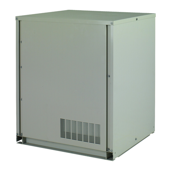
Daikin RKXYQ5T7Y1B Installation And Operation Manual (44 pages)
Compressor unit for indoor installation
Brand:
Daikin
| Category:
Air Compressor
| Size: 4.34 MB
Table of Contents
Table of Contents
4
About the Documentation
5
About this Document
5
For the Installer
5
About the Box
5
Compressor Unit
5
To Remove the Accessories from the Compressor Unit
5
To Remove the Transportation Stay
6
To Remove the Transportation EPS
6
About the Units and Options
6
About the Compressor Unit and Heat Exchanger Unit
6
System Layout
6
Combining Units and Options
6
Possible Options for the Compressor Unit and Heat Exchanger Unit
6
Preparation
7
Preparing Installation Site
7
Installation Site Requirements of the Compressor Unit
7
Preparing Refrigerant Piping
7
Refrigerant Piping Requirements
7
Refrigerant Piping Material
8
To Select the Piping Size
8
To Select Refrigerant Branch Kits
8
Refrigerant Piping Length and Height Difference
9
Preparing Electrical Wiring
9
About Electrical Compliance
9
Safety Device Requirements
9
Installation
10
Opening the Units
10
To Open the Compressor Unit
10
Mounting the Compressor Unit
10
Guidelines When Installing the Compressor Unit
10
Connecting the Refrigerant Piping
10
Using the Stop Valve and Service Port
10
To Remove the Pinched Pipes
11
To Connect the Refrigerant Piping to the Compressor Unit
12
Checking the Refrigerant Piping
13
About Checking the Refrigerant Piping
13
Checking Refrigerant Piping: General Guidelines
13
Checking Refrigerant Piping: Setup
13
To Perform a Leak Test
14
To Perform Vacuum Drying
14
To Insulate the Refrigerant Piping
14
Charging Refrigerant
15
Precautions When Charging Refrigerant
15
To Determine the Additional Refrigerant Amount
15
To Charge Refrigerant
15
Error Codes When Charging Refrigerant
16
To Fix the Fluorinated Greenhouse Gases Label
16
Connecting the Electrical Wiring
17
Field Wiring: Overview
17
Guidelines When Connecting the Electrical Wiring
17
To Connect the Electrical Wiring on the Compressor Unit
17
Finishing the Compressor Unit Installation
18
To Finish the Transmission Wiring
18
Configuration
18
Making Field Settings
18
About Making Field Settings
18
To Access the Field Setting Components
19
Field Setting Components
19
To Access Mode 1 or 2
20
To Use Mode 1 (and Default Situation)
20
To Use Mode 2
21
Mode 1 (and Default Situation): Monitoring Settings
21
Mode 2: Field Settings
23
To Connect the PC Configurator to the Compressor Unit
26
Commissioning
26
Precautions When Commissioning
26
Checklist before Commissioning
26
Checklist During Commissioning
27
About Test Run
27
To Perform a Test Run (7-Leds Display)
27
To Perform a Test Run (7-Segments Display)
27
Correcting after Abnormal Completion of the Test Run
28
Operating the Unit
28
Troubleshooting
28
Solving Problems Based on Error Codes
28
Error Codes: Overview
28
Technical Data
32
Piping Diagram: Compressor Unit and Heat Exchanger Unit
32
Wiring Diagram: Compressor Unit
33
For the User
34
10 About the System
34
System Layout
34
User Interface
34
Operation
34
Operation Range
34
Operating the System
34
About Operating the System
34
About Cooling, Heating, Fan Only, and Automatic Operation
35
About the Heating Operation
35
To Operate the System (WITHOUT Cool/Heat Changeover Remote Control Switch)
35
To Operate the System (with Cool/Heat Changeover Remote Control Switch)
35
Using the Dry Program
35
About the Dry Program
35
To Use the Dry Program (WITHOUT Cool/Heat Changeover Remote Control Switch)
36
To Use the Dry Program (with Cool/Heat Changeover Remote Control Switch)
36
Adjusting the Air Flow Direction
36
About the Air Flow Flap
36
Setting the Master User Interface
36
About Setting the Master User Interface
36
To Designate the Master User Interface (VRV DX)
37
13 Maintenance and Service
37
About the Refrigerant
37
After-Sales Service and Warranty
37
Warranty Period
37
Recommended Maintenance and Inspection
37
Troubleshooting
37
Error Codes: Overview
38
Symptoms that Are NOT System Malfunctions
39
Symptom: the System Does Not Operate
39
Symptom: Cool/Heat Cannot be Changed over
39
Symptom: Fan Operation Is Possible, but Cooling and Heating Do Not Work
39
Advertisement
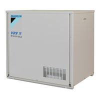
Daikin RKXYQ5T7Y1B Installation And Operation Manual (32 pages)
VRV IV compressor unit for indoor installation
Brand:
Daikin
| Category:
Air Compressor
| Size: 2.43 MB
Table of Contents
Table of Contents
3
About the Documentation
4
About this Document
4
For the Installer
4
About the Box
4
Compressor Unit
4
To Remove the Accessories from the Compressor Unit
4
To Remove the Transportation Stay
4
About the Units and Options
5
About the Compressor Unit and Heat Exchanger Unit
5
System Layout
5
Preparation
5
Preparing Installation Site
5
Installation Site Requirements of the Compressor Unit
5
Preparing Refrigerant Piping
5
Refrigerant Piping Requirements
5
Refrigerant Piping Material
5
To Select the Piping Size
6
To Select Refrigerant Branch Kits
6
Preparing Electrical Wiring
6
Safety Device Requirements
6
Installation
7
Opening the Units
7
To Open the Compressor Unit
7
Mounting the Compressor Unit
7
Guidelines When Installing the Compressor Unit
7
Connecting the Refrigerant Piping
7
Using the Stop Valve and Service Port
7
To Remove the Pinched Pipes
8
To Connect the Refrigerant Piping to the Compressor Unit
9
Checking the Refrigerant Piping
10
About Checking the Refrigerant Piping
10
Checking Refrigerant Piping: General Guidelines
10
Checking Refrigerant Piping: Setup
10
To Perform a Leak Test
11
To Perform Vacuum Drying
11
To Insulate the Refrigerant Piping
11
Charging Refrigerant
11
Precautions When Charging Refrigerant
11
To Determine the Additional Refrigerant Amount
12
To Charge Refrigerant
12
Error Codes When Charging Refrigerant
13
To Fix the Fluorinated Greenhouse Gases Label
13
Connecting the Electrical Wiring
13
Field Wiring: Overview
13
Guidelines When Connecting the Electrical Wiring
14
To Connect the Electrical Wiring on the Compressor Unit
14
Finishing the Compressor Unit Installation
15
To Finish the Transmission Wiring
15
Configuration
15
Making Field Settings
15
About Making Field Settings
15
To Access the Field Setting Components
15
Field Setting Components
15
To Access Mode 1 or 2
16
To Use Mode 1 (and Default Situation)
16
To Use Mode 2
17
Mode 1 (and Default Situation): Monitoring Settings
17
Mode 2: Field Settings
18
To Connect the PC Configurator to the Compressor Unit
20
Commissioning
20
Precautions When Commissioning
20
Checklist before Commissioning
20
Checklist During Commissioning
21
About Test Run
21
To Perform a Test Run (7-Leds Display)
21
Correcting after Abnormal Completion of the Test Run
22
Operating the Unit
22
Troubleshooting
22
Solving Problems Based on Error Codes
22
Error Codes: Overview
22
Technical Data
24
Piping Diagram: Compressor Unit and Heat Exchanger Unit
24
Wiring Diagram: Compressor Unit
24
For the User
25
10 About the System
25
System Layout
25
User Interface
25
Operation
25
Operation Range
25
Operating the System
26
About Operating the System
26
About Cooling, Heating, Fan Only, and Automatic Operation
26
About the Heating Operation
26
To Operate the System (WITHOUT Cool/Heat Changeover Remote Control Switch)
26
To Operate the System (with Cool/Heat Changeover Remote Control Switch)
26
Using the Dry Program
27
About the Dry Program
27
To Use the Dry Program (WITHOUT Cool/Heat Changeover Remote Control Switch)
27
To Use the Dry Program (with Cool/Heat Changeover Remote Control Switch)
27
Adjusting the Air Flow Direction
27
About the Air Flow Flap
27
Setting the Master User Interface
27
About Setting the Master User Interface
27
To Designate the Master User Interface (VRV DX)
28
13 Maintenance and Service
28
After-Sales Service and Warranty
28
Warranty Period
28
Recommended Maintenance and Inspection
28
Troubleshooting
28
Error Codes: Overview
29
Symptoms that Are Not Air Conditioner Troubles
30
Symptom: the System Does Not Operate
30
Symptom: Cool/Heat Cannot be Changed over
30
Symptom: Fan Operation Is Possible, but Cooling and Heating Do Not Work
30
Symptom: the Fan Strength Does Not Correspond to the Setting
30
Symptom: the Fan Direction Does Not Correspond to the Setting
30
Unit
30
Symptom: White Mist Comes out of a Unit (Indoor Unit, Heat Exchanger Unit)
30
Advertisement
Related Products
Daikin VRV IV RKXYQ5T8Y1B Series
Daikin RKXYQ-T8
Daikin RKXYQ-T
Daikin VRV IV RDXYQ5T8V1B Series
Daikin VRV IV RKXYQ8T7Y1B
Daikin RKS25E2V1B
Daikin RK35JV1NB
Daikin RKS60FVLT
Daikin RKD60JVE
Daikin RKC50QVM
Daikin Categories
Air Conditioner
Heat Pump
Remote Control
Chiller
Fan
More Daikin Manuals
Login
Sign In
OR
Sign in with Facebook
Sign in with Google
Upload manual
Upload from disk
Upload from URL