Sign In
Upload
Manuals
Brands
Daikin Manuals
Air Conditioner
FTKS25D3VML
Daikin FTKS25D3VML Remote Control Manuals
Manuals and User Guides for Daikin FTKS25D3VML Remote Control. We have
2
Daikin FTKS25D3VML Remote Control manuals available for free PDF download: Service Manual
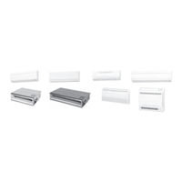
Daikin FTKS25D3VML Service Manual (355 pages)
super multi nx
Brand:
Daikin
| Category:
Air Conditioner
| Size: 15 MB
Table of Contents
Table of Contents
3
Introduction
6
Safety Cautions
6
Used Icons
10
Part 1 List of Functions
12
List of Functions
13
Cooling Only Models
13
Heat Pump Models
18
Part 2 Specifications
24
Indoor Units - Cooling Only
25
Outdoor Units - Cooling Only
34
Indoor Units - Heat Pump
35
Outdoor Units - Heat Pump
46
Part 3 Printed Circuit Board Connector Wiring Diagram
48
Printed Circuit Board Connector Wiring Diagram
49
Wall Mounted Type
49
Duct Connected Type
58
Floor / Ceiling Suspended Dual Type
60
Floor Standing Type
63
Ceiling Suspended Type
65
Outdoor Units
67
Part 4 Function and Control
70
Main Functions
71
Frequency Principle
71
Power-Airflow Dual Flaps, Wide Angle Louvers and Auto-Swing
73
Operation Starting Control
75
Fan Speed Control for Indoor Units
76
Programme Dry Function
77
Automatic Operation
78
Thermostat Control
79
Night Set Mode
80
ECONO Mode
81
INTELLIGENT EYE (Wall Mounted Type Only)
82
HOME LEAVE Operation
84
Inverter POWERFUL Operation
85
Other Functions
86
Function of Main Structural Parts
88
Main Structural Parts
88
Function of Thermistor
89
Control Specification
93
Mode Hierarchy
93
Frequency Control
94
Controls at Mode Changing / Start-Up
97
Compressor Protection Function
98
Discharge Pipe Control
99
Input Current Control
99
Freeze-Up Protection Control
100
Heating Peak-Cut Control
100
Fan Control
101
Liquid Compression Protection Function 2
101
Defrost Control
102
Electronic Expansion Valve Control
103
Malfunctions
107
Forced Operation Mode
108
Wiring-Error Check
109
Additional Function
111
Part 5 Operation Manual
114
System Configuration
115
Operation Instructions
115
Instruction
116
FTK(X)S, FTXG, CTXG, FDK(X)S, FLK(X)S Series
116
Safety Precautions
117
FVXS Series
192
Air Flow Selection
203
FHQ Series
223
Temperature Setting
229
Fan Speed Control
229
Part 6 Service Diagnosis
236
Caution for Diagnosis
237
Troubleshooting with Operation Lamp
237
Problem Symptoms and Measures
239
Service Check Function
240
Check Method 1
240
Check Method 2
242
Code Indication on the Remote Control
244
Error Codes and Description of Fault
244
Troubleshooting
245
Indoor Units
245
Outdoor Units
246
Indoor Unit PCB Abnormality
247
Freeze-Up Protection Control or High Pressure Control
248
Fan Motor or Related Abnormality
250
Thermistor or Related Abnormality (Indoor Unit)
253
Front Panel Open / Close Fault
254
Signal Transmission Error (between Indoor and Outdoor Unit)
255
Unspecified Voltage (between Indoor and Outdoor Units)
257
Freeze-Up Protection Control
258
Outdoor Unit PCB Abnormality
260
OL Activation (Compressor Overload)
261
Compressor Lock
262
DC Fan Lock
263
Input over Current Detection
264
Discharge Pipe Temperature Control
266
High Pressure Control in Cooling
267
Compressor Sensor System Abnormality
269
Position Sensor Abnormality
271
CT or Related Abnormality
272
Thermistor or Related Abnormality (Outdoor Unit)
274
Sienbe12
275
Electrical Box Temperature Rise
276
Radiation Fin Temperature Rise
278
Output over Current Detection
280
Insufficient Gas
282
Low-Voltage Detection or Over-Voltage Detection
284
Signal Transmission Error (on Outdoor Unit PCB)
285
Anti-Icing Function in Other Rooms / Unspecified Voltage
286
(Between Indoor and Outdoor Units)
286
Anti-Icing Function in Other Rooms / Unspecified Voltage (between Indoor and Outdoor Units)
286
Check
287
How to Check
287
Electronic Expansion Valve Check
288
Four Way Valve Performance Check
289
Installation Condition Check
291
Discharge Pressure Check
292
Power Supply Waveforms Check
293
Capacitor Voltage Check
294
Power Transistor Check
294
Main Circuit Electrolytic Capacitor Check
295
Hall IC Check
296
Part 7 Removal Procedure
298
Outdoor Unit
299
Removal of the Panels and Plates
299
Removal of the Electrical Box
303
Removal of the PCB
311
Removal of the Propeller Fan / Fan Motor
317
Removal of the Sound Blanket
319
Removal of Electronic Expansion Valve Coil, Four Way Valve Coil and Thermistor
323
Removal of the Distributor
326
Removal of the Four Way Valve
327
Removal of the Compressor
328
Part 8 Others
331
Others
331
Test Run from the Remote Control
331
Jumper Settings
332
Part 9 Appendix
334
Piping Diagrams
335
Indoor Units
335
Outdoor Units
341
Wiring Diagrams
342
Indoor Units
342
Outdoor Units
347
Index
348
Advertisement
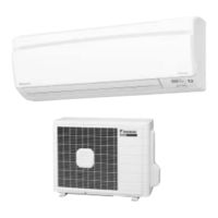
Daikin FTKS25D3VML Service Manual (228 pages)
Brand:
Daikin
| Category:
Air Conditioner
| Size: 14 MB
Table of Contents
Table of Contents
3
Introduction
6
Safety Cautions
6
Caution in Repair
6
Cautions Regarding Products after Repair
7
Inspection after Repair
8
Using Icons
9
Using Icons List
9
Part 1 List of Functions
10
List of Functions
11
Part 2 Specifications
16
Cooling Only
17
Heat Pump
30
Part 3 Printed Circuit Board Connector Wiring Diagram
48
Printed Circuit Board Connector Wiring Diagram
49
Indoor Unit
49
Outdoor Unit
51
Function and Control
54
Main Functions
55
Frequency Principle
55
Air Flow Direction Control
57
Fan Speed Control for Indoor Units
58
Programme Dry Function
59
Automatic Operation
60
Thermostat Control
61
NIGHT SET Mode
62
ECONO Mode
63
Intelligent Eye
64
Inverter POWERFUL Operation
66
Other Functions
67
Function of Thermistor
68
Heat Pump Model
68
Cooling Only Model
69
Control Specification
70
Mode Hierarchy
70
Frequency Control
71
Controls at Mode Changing / Start-Up
73
Discharge Pipe Control
74
Input Current Control
75
Freeze-Up Protection Control
76
Heating Peak-Cut Control
76
Fan Control
77
Liquid Compression Protection Function 2
77
Defrost Control
78
Electronic Expansion Valve Control
79
Malfunctions
82
Forced Operation Mode
83
Additional Function
83
Facility Setting Jumper (Cooling at Low Outdoor Temperature)
84
Part 5 System Configuration
86
System Configuration
87
Instruction
88
Safety Precautions
88
Installation Site
89
Electrical Work
89
Names of Parts
90
Remote Control
92
Preparation before Operation
93
To Set the Clock
95
AUTO · DRY · COOL · HEAT · FAN Operation
96
To Change the Air Flow Rate Setting
97
Adjusting the Air Flow Direction
98
POWERFUL Operation
100
OUTDOOR UNIT SILENT Operation
101
ECONO Operation
102
INTELLIGENT EYE Operation
103
TIMER Operation
105
To Use on Timer Operation
106
To Combine on Timer and off Timer
106
Care and Cleaning
107
Air Filter
108
Before a Long Idle Period
109
Troubleshooting
110
Check Again
111
Call the Service Shop Immediately
112
Fault Diagnosis
113
Part 6 Service Diagnosis
114
Caution for Diagnosis
115
Problem Symptoms and Measures
116
Service Check Function
117
Troubleshooting
120
Error Codes and Description
120
Indoor Unit PCB Abnormality
121
Freeze-Up Protection Control or High Pressure Control
122
Fan Motor (DC Motor) or Related Abnormality
124
Thermistor or Related Abnormality (Indoor Unit)
126
Signal Transmission Error (between Indoor and Outdoor Unit)
127
Unspecified Voltage (between Indoor and Outdoor Units)
128
Outdoor Unit PCB Abnormality
129
OL Activation (Compressor Overload)
130
Compressor Lock
131
DC Fan Lock
132
Input over Current Detection
133
Four Way Valve Abnormality
134
Discharge Pipe Temperature Control
136
High Pressure Control in Cooling
137
Compressor System Sensor Abnormality
139
Position Sensor Abnormality
140
DC Voltage / Current Sensor Abnormality
141
Thermistor or Related Abnormality (Outdoor Unit)
142
Electrical Box Temperature Rise
144
Radiation Fin Temperature Rise
146
Output over Current Detection
148
Insufficient Gas
150
Over-Voltage Detection
152
Check
153
How to Check
153
Fan Motor Connector Output Check
153
Electronic Expansion Valve Check
153
Four Way Valve Performance Check
154
Thermistor Resistance Check
155
Installation Condition Check
156
Discharge Pressure Check
156
Outdoor Unit Fan System Check
157
Power Supply Waveforms Check
157
Power Transistor Check
158
Part 7 Removal Procedure
160
Indoor Unit
161
Removal of Air Filter
161
Removal of Front Panel
163
Removal of Front Grille
165
Removal of Horizontal Blades and Vertical Blades
168
Removal of Electrical Box
171
Removal of PCB
174
Removal of Drain Pan Unit
180
Removal of Fan Motor
184
Removal of Heat Exchanger
186
Removal of Fan Rotor
189
Outdoor Unit
192
Removal of Panels and Fan Motor
192
Removal of Electrical Box
199
Removal of Reactor and Partition Plate
201
Removal of Sound Blanket
203
Removal of Four Way Valve
205
Removal of Compressor
207
Removal of PCB
209
Part 8 Others
212
Others
213
Test Run from the Remote Controller
213
Jumper Settings
214
Part 9 Appendix
216
Piping Diagrams
217
Indoor Units
217
Outdoor Units
218
Wiring Diagrams
220
Indoor Units
220
Outdoor Units
220
Index
222
Drawings & Flow Charts
226
Advertisement
Related Products
Daikin FTKS25D3VMW(L)
Daikin FTKS25D3VMW
Daikin FTKS25DVMW
Daikin FTKS25DVMW9
Daikin FTKS25DAVMW(L)
Daikin FTKS25D2(3)VMW(L)
Daikin FTKS25DVM
Daikin FTKS25DVMT
Daikin FTKS25D2VMW
Daikin FTKS25D(2)VMW(L)(9)
Daikin Categories
Air Conditioner
Heat Pump
Chiller
Remote Control
Air Handlers
More Daikin Manuals
Login
Sign In
OR
Sign in with Facebook
Sign in with Google
Upload manual
Upload from disk
Upload from URL