Sign In
Upload
Manuals
Brands
Covidien Manuals
Medical Equipment
Nellcor PM1000N
Covidien Nellcor PM1000N Manuals
Manuals and User Guides for Covidien Nellcor PM1000N. We have
1
Covidien Nellcor PM1000N manual available for free PDF download: Service Manual
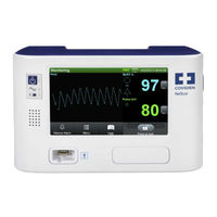
Covidien Nellcor PM1000N Service Manual (236 pages)
Bedside Respiratory Patient Monitoring System
Brand:
Covidien
| Category:
Medical Equipment
| Size: 2.72 MB
Table of Contents
Table of Contents
3
1 Introduction
13
Overview
13
Intended Audience
13
Safety Information
14
Safety Symbols
14
Warnings
14
Table 1-1. Safety Symbol Definitions
14
Cautions
16
Obtaining Technical Assistance
17
Technical Services
17
On-Screen Help
18
Related Documents
18
Warranty Information
18
2 Product Specifications
19
Overview
19
Physical Characteristics
19
Electrical Requirements
19
Power
19
Battery
20
Rating of Nurse Call Relay
20
Environmental Conditions
21
Operating
21
Transport and Storage
21
Sensor Accuracy and Ranges
22
Table 2-1. Nellcor™ Sensor Accuracy and Ranges
22
Sound Pressure
23
Product Compliance
23
Table 2-2. Nellcor™ Sensor Operating Range and Power Dissipation
23
Table 2-3. Sound Pressure in Decibels
23
Manufacturer's Declaration and Guidance
24
Electromagnetic Compatibility (EMC)
24
Table 2-4. Frequency Band, Output Power, and Modulation Type
24
Table 2-5. Electromagnetic Emissions Guidelines and Compliance
25
Electromagnetic Emissions
25
Table 2-6. Electromagnetic Immunity Guidelines and Compliance
26
Table 2-7. Recommended Separation Distance Calculations
27
Table 2-8. Recommended Separation Distances
28
Table 2-9. Sensor and Cable Length
29
Ground Integrity
30
Safety Tests
30
Table 2-10. Earth and Enclosure Leakage Current Specifications
30
Table 2-11. Patient Applied and Patient Isolation Risk Current
31
3 Theory of Operations
33
Overview
33
Block Diagram
33
Figure 3-1. Block Diagram
33
Theoretical Principles
34
Automatic Calibration
35
Functional Testers and Patient Simulators
35
Unique Technologies
36
Functional Versus Fractional Saturation
36
Measured Versus Calculated Saturation
36
Data Update Period, Data Averaging, and Signal Processing
37
Figure 3-2. Oxyhemoglobin Dissociation Curve
37
System Features
38
Nellcor™ Sensor Technology
38
Satseconds™ Alarm Management Parameter
39
Figure 3-4. First Spo 2 Event: no Satseconds Alarm
40
Figure 3-5. Second Spo 2 Event: no Satseconds Alarm
41
Oximax SPD™ Alert Parameter
43
Figure 3-7. Clinically Significant Desaturation Patterns
44
Pulse Rate Delay Alarm Management Parameter
45
4 Product Overview
47
Overview
47
Product Description
47
Indications for Use
47
List of Components
48
Synopsis
48
Table 4-1. Typical Packing List
48
Product Views
49
Front Panel
49
Figure 4-1. Front Panel
49
Monitoring Screen
50
Figure 4-2. Sample Monitoring Screen Elements
50
Rear Panel
52
Labeling Symbology
53
Table 4-2. Labeling Symbols and Descriptions
53
5 Installation
55
Overview
55
Safety Reminders
55
Product Setup
57
Mounting Options and Transport Considerations
57
Connection to an AC Power Source
57
Battery Insertion
58
Battery Charge
59
Battery Power Usage
60
Connection to Nellcor™ Sensors
61
Figure 5-1. Sensor Cable Insertion into Interface Cable
61
6 Operation
63
Overview
63
Power
63
AC Power
64
Battery Power
64
Table 6-1. Battery Power Status
65
Power up
66
System Resets
68
Automatic Shutdown and Power off
68
Figure 6-1. Sample POST Splash Screen
68
Nellcor™ Sensor Usage
69
Sensor Detection
69
Sensor Detection Failure
70
Figure 6-2. Sensor Type Message
70
User Interface
71
Default Monitoring Screen and Trend Data
71
Status Messages and Alarms in the Monitoring Status Field
71
Figure 6-3. Default Monitoring Screen Layout
71
Alarm Management and Status Messages
72
Figure 6-4. Sample User Prompt Message: READY
73
Figure 6-5. Sample Status Message: MONITORING
73
Figure 6-6. High Priority Alarm: BATTERY CRITICALLY LOW
73
Figure 6-7. Medium Priority Alarm: Spo 2 LOW
73
Figure 6-8. Low Priority Alarm: SENSOR off
74
Audible Alarm Management
75
Figure 6-9. Sample Alarm Limit Violations
75
Visual Alarm Management
77
HELP Option
78
Service Mode
78
Table 6-2. Possible User Interface Settings
78
Table 6-3. Possible Alarm Management Settings
79
Table 6-4. Possible Data Interface Settings
80
Table 6-5. Possible Service Functions
80
Figure 6-10. Prompt to Enter SERVICE MODE
81
Settings Menu
81
Alarm Limits
82
Alarm System
82
Display Settings
85
Figure 6-11. Default Monitoring Screen Layout
86
Logs Menu
93
Service Menu
93
Covidien Service Menu
94
About Monitor Menu
95
Parameter Activation Menu
95
7 Trend Data Access
97
Overview
97
Trend Data Management
97
Trend Data Basics
97
Data Port Connectivity
98
Overview
98
Table 7-1. Input and Output Configuration Options
98
Typical Equipment Used for Connectivity
99
Data Port Configuration Information
99
Table 7-2. Sample Equipment Types
99
Table 7-3. DB-15 Signal Pinouts
101
Figure 7-1. DB-15 Pin Layout
101
Table 7-4. RJ-45 Signal Pinouts
103
Figure 7-2. RJ-45 Receptacle
103
Figure 7-3. RJ-45 Pin Layout
103
Table 7-5. USB Signal Pinouts
104
Figure 7-4. USB Pin Layout
104
Table 7-6. Network Configuration Icons
105
Figure 7-5. New Network Connection Windows
107
Figure 7-6. New Network Connection Windows
108
Data Port Communications
110
Using the Nurse Call Interface
110
Nurse Call Feature
110
Table 7-7. Nurse Call Relay Pin States
111
Setting Nurse Call RS-232 Polarity
112
Figure 7-7. Nurse Call Polarity Screen
112
Calculating the Analog Voltage Output
113
Table 7-8. Analog Pinouts
113
8 Performance Considerations
115
Overview
115
Oximetry Considerations
115
Monitoring System Constraints
115
Nellcor™ Sensor Performance Considerations
115
Patient Conditions
117
Reducing EMI (Electromagnetic Interference)
118
9 Product Maintenance
121
Overview
121
Cleaning
121
Periodic Safety Checks
121
Service and Upgrades
122
Storage
122
Monitoring System Transport and Storage
122
Removed Battery Storage
122
10 Modification and Testing
123
Overview
123
Table 10-1. Possible User Interface Settings
124
Table 10-2. Possible Alarm Management Settings
125
Table 10-3. Possible Data Interface and Service Settings
126
Setting Institutional Defaults
127
Figure 10-1. Prompt to Enter SERVICE MODE
127
Performance Verification
130
Overview
130
Required Equipment
130
Table 10-4. Equipment and Descriptions
130
Safety Testing Standards
131
Battery Check
132
Battery Power
132
Battery Charge
132
Performance Tests
133
Power-On Defaults and Alarm Ranges
133
Operational Setup
139
Figure 10-2. Sample: Configuring Alarms
140
Figure 10-3. Sample: Configuring Alarms with Silenced Alarm
141
Overall Performance Check
144
Pulse Oximetry Functional Tests
146
Figure 10-4. Sensor Identification
146
Figure 10-5. SRC-MAX Functional Tester
147
Table 10-5. Functional Tests Options
148
Figure 10-10. MOD Test: BPM 60, Spo 2 75, and MOD Low
153
Figure 10-11. MOD Test: BPM 60, Spo 2 75, and MOD High
154
Figure 10-12. MOD Test: BPM 200, Spo 2 75, and MOD High
155
Figure 10-13. MOD Test: BPM 60, Spo 2 90, and MOD High
156
Figure 10-14. LIGHT Test: BPM 60, Spo 2 75, MOD Low, Light Low
157
Figure 10-15. LIGHT Test: BPM 60, Spo 2 75, MOD Low, Light High
158
Figure 10-16. LIGHT Test: BPM 200, Spo 2 75, MOD Low, Light High
159
Figure 10-17. LIGHT Test: BPM 60, Spo 2 90, MOD Low, Light High
160
Figure 10-18. LIGHT Test: BPM 60, Spo 2 90, MOD High, Light High
161
Setting Nurse Call
162
Test Data Sheet Form
164
Table 10-6. Performance and Functional Tests
164
Table 10-7. Electrical Safety Tests
165
Monitoring Screen Calibration
166
Figure 10-19. Initial Calibration Screen
166
Software and Firmware Upgrades
167
11 Troubleshooting
169
Overview
169
System Condition Categories
169
Figure 11-1. Ready Prompt
170
Figure 11-2. Sensor Disconnected Message and Help Screen
170
Figure 11-3. Stacked Alarm/Alerts
171
User Prompts and Messages
172
Alarms and Error Conditions
172
Alarms
172
Table 11-1. Common User Prompts and Messages
172
Table 11-2. Initial Alarm Priority for Errors
173
Figure 11-4. Sample Speaker Failure Message
176
Correctable Error Conditions
177
Table 11-3. Common Correctable Problems and Resolutions
177
Power Failure Issues
179
Table 11-4. Power Failure Issues
180
Monitoring Screen Issues
181
Alarm Issues
182
Communication Issues
184
Table 11-7. Common Prompts and Error Messages
184
Operational Performance Issues
185
Hardware Issues
185
Table 11-8. Common Operational Performance Issues
185
Table 11-9. Common Prompts and Error Messages
185
System Errors and Software Issues
187
Non-Correctable Failures
187
Figure 11-5. System Error
187
Product Return
188
12 Repair
189
Overview
189
Spare Parts List
189
Table 12-1. Available Spare Parts
189
Figure 12-1. Exploded View of Removable Components
191
Figure 12-2. Exploded View of Internal Components
192
Repair Prerequisites and Required Equipment
193
Basic Preventive Maintenance
194
Table 12-2. Required Equipment
194
Battery or Battery Access Door Replacement
195
Figure 12-3. External Fuse Removal
195
Fuse Removal and Replacement
195
Figure 12-4. Battery Removal
196
Rubber Feet Replacement
196
Figure 12-5. Rubber Feet Replacement
197
Chassis Disassembly and Reassembly
198
Parameter Module Replacement
198
Figure 12-6. Parameter Module Screw Removal
199
Figure 12-7. Parameter Module Tab Release
200
Figure 12-8. Parameter Module Assembly Removal
200
Figure 12-9. Parameter Module Disassembly
202
Figure 12-10. Parameter Board PCB and Oximetry Module Removal
204
Monitoring System Chassis Disassembly
205
Figure 12-11. Corner Chassis Screws Removal
206
Table 12-3. Main PCB Connections
207
Monitoring System Chassis Reassembly
208
Figure 12-12. Initial Chassis Disassembly
208
Power Components Replacement
209
Power Entry Module (PEM) Replacement
210
Right Power Cable Assembly Replacement
210
Figure 12-13. Right Power Cable Assembly Replacement
211
Battery Components Replacement
212
Figure 12-14. Battery Cradle Removal
213
Figure 12-15. Power Supply PCB Removal
215
Figure 12-16. Battery Interconnect PCB Removal
217
Figure 12-17. Cooling Fan Removal
218
Left Power Cable Assembly Replacement
219
Figure 12-18. Left Power Cable Assembly Replacement
219
Front Panel Components Replacement
220
Main PCB Components Replacement
221
Table 12-4. Main PCB Connections
221
Figure 12-19. Main PCB Connectors
222
Figure 12-20. Antennae PCB and UFL Connectors Removal
224
Figure 12-21. Single Board Computer (SBC) Removal
225
LCD Assembly with Overlay Replacement
227
Figure 12-22. LCD Assembly Removal
228
Return Authorization and Shipment
229
General Instructions for Return
229
Repackage in Original Carton
230
Figure 12-23. Components to Repackage in Original Carton
230
Repackage in an Alternate Carton
231
Index
233
Advertisement
Advertisement
Related Products
Covidien Nellcor PM100N
Covidien Nellcor PM10N
Covidien Nellcor PM1000N-RR
Covidien Nellcor OxiMax N-600x
Covidien Nellcor Series
Covidien Nellcor GR101704-RR
Covidien Nellcor GR101704
Covidien Nellcor FLEXMAX
Covidien Nellcor FLEXMAX-P
Covidien Nellcor
Covidien Categories
Medical Equipment
Accessories
Thermometer
Measuring Instruments
Water Pump
More Covidien Manuals
Login
Sign In
OR
Sign in with Facebook
Sign in with Google
Upload manual
Upload from disk
Upload from URL