Sign In
Upload
Manuals
Brands
Chery Manuals
Automobile
A1 2009
Chery A1 2009 Manuals
Manuals and User Guides for Chery A1 2009. We have
1
Chery A1 2009 manual available for free PDF download: Service Manual
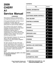
Chery A1 2009 Service Manual (1080 pages)
Brand:
Chery
| Category:
Automobile
| Size: 10.85 MB
Table of Contents
Vehicle Information
10
Table of Contents
10
Vehicle Identification Number (Vin)
11
VIN Location
11
VIN Identification Codes
12
International Symbols
14
Fastener Usage
15
Electrical Information
21
Connector Symbols
22
How to Read Electrical Schematics
22
Option Splices
23
Electrical Schematic - Example
24
Electrical Schematic Index
26
How to Locate Electrical Schematics in the Service Manual
26
Engine 02
30
1.3L Engine Mechanical
30
General Information
33
Description
34
Diagnosis & Testing
42
Engine Performance Diagnostics
42
Engine Mechanical Diagnostics
43
Cylinder Compression Pressure Test
44
Cylinder Head Gasket Test
44
Accessory Drive Belt
45
On-Vehicle Service
45
Removal & Installation
45
Air Cleaner Element
47
Air Cleaner Housing
47
Removal & Installation
47
Cylinder Head Cover
48
Removal & Installation
48
Camshaft
51
Removal & Installation
51
Cylinder Head
55
Removal & Installation
55
Front Crankshaft Oil Seal
57
Removal & Installation
57
Rear Crankshaft Oil Seal
58
Removal & Installation
58
Engine Mounts
60
Removal & Installation - Left Mount
60
Removal & Installation - Right Mount
60
Removal & Installation - Front Mount
61
Removal & Installation - Rear Mount
61
Engine Assembly
62
Removal & Installation
62
Engine Timing Belt
69
Removal & Installation
69
Exhaust Manifold
73
Removal & Installation
73
Intake Manifold
75
Removal & Installation
75
Oil Filter
78
Removal & Installation
78
Oil Pan
79
Removal & Installation
79
Oil Pump
80
Removal & Installation
80
Oil Strainer
81
Removal & Installation
81
Disassembly
82
Engine Block
82
Engine Unit Repair
82
Specifications
82
Assembly
84
Inspection
84
Pistons
85
Specifications
85
Disassembly
86
Inspection
87
Assembly
89
Connecting Rods
90
Disassembly
90
Specifications
90
Assembly
91
Inspection
91
Crankshaft
92
Disassembly
92
Specifications
92
Inspection
93
Assembly
94
Cylinder Head
95
Disassembly
95
Assembly
97
Inspection
97
Camshaft
98
Specifications
98
Disassembly
99
Inspection
99
Assembly
101
Disassembly
102
Specifications
102
Valve & Valve Guides
102
Inspection
103
Assembly
104
Specifications
105
Valve Springs
105
Disassembly
106
Assembly
107
Inspection
107
Electronic Engine Controls 03
108
Special Tools
113
Electrical Schematics
116
Diagnosis & Testing
128
Diagnostic Help
128
Ground Inspection
128
Intermittent DTC Troubleshooting
128
Diagnostic Trouble Code (DTC) List
129
Power Supply and Ground Circuit
133
Power Supply and Ground Circuit Test
133
Diagnostic Trouble Code (DTC) Tests
140
Position Correlation Error
140
High Input
160
Performance
220
P0506 - Idle Control System RPM Lower than Expected
247
P0562 - System Voltage Low Voltage P0563 - System Voltage High Voltage
249
P0602 - Control Module ECM Programming Error
254
P0604 - Internal Controller Module
256
P0605 - Internal Controller Module
256
ROM Test Error, P0606 - ECM
256
P0645 - A/C Clutch Relay Circuit
258
P1545 - Throttle Position Control Performance
262
P2138 - Pedal Position Sensor Performance
269
Description
276
Engine Coolant Temperature Sensor
276
On-Vehicle Service
276
Operation
276
Removal & Installation
276
Description
277
Knock Sensor
277
Operation
277
Oxygen Sensor
277
Removal & Installation
277
Upstream Oxygen Sensor
277
Downstream Oxygen Sensor
278
Removal & Installation - Downstream Oxygen Sensor
278
Removal & Installation - Upstream Oxygen Sensor
278
Camshaft Position Sensor
279
Crankshaft Position Sensor
279
Description
279
Operation
279
Removal & Installation
279
Description
280
Operation
280
Removal & Installation
280
Vehicle Speed Sensor
280
Accelerator Sensor
281
Description
281
Manifold Absolute Pressure Sensor
281
Operation
281
Removal & Installation
281
Accelerator Pedal Position Sensor
282
Description
282
Electronic Throttle Control Actuator
282
Operation
282
Removal & Installation
282
Description
283
Engine Control Module (ECM)
283
Operation
283
Removal & Installation
283
Removal & Installation
284
Engine Symptom Diagnosis
285
Diagnostic Help
286
General Troubleshooting Checks
286
Symptom Diagnostic Test List
286
Symptom Diagnostic Tests
286
Visual Inspection
286
Engine Cranks Normal but will Not Start
287
Engine will Not Crank
289
Hard Start / Long Crank / Erratic Start / Erratic Crank
291
Fast Idle
294
Lack / Loss of Power
295
Back Fires
298
Engine Poor Driveability
300
Low Idle / Stalls During Deceleration
304
Idle Speed Slow Return to Normal Idle
306
Ignition Control
307
Description
308
General Information
308
Operation
308
Specifications
308
Special Tools
309
Electrical Schematics
310
Description
311
Ignition Coil
311
On-Vehicle Service
311
Operation
311
Removal & Installation
311
Removal & Installation
312
Spark Plug Wire
312
Removal & Installation
313
Spark Plug
313
Evaporative Emissions
314
Description
315
General Information
315
Operation
315
Specifications
315
Special Tools
316
Electrical Schematics
317
Description
318
On-Vehicle Service
318
Operation
318
Removal & Installation
318
Vapor Canister Control Valve
318
Description
319
Operation
319
Vapor Canister
319
Fuel Delivery 04
320
Fuel Delivery System
324
General Information
324
Diagnosis & Testing
328
Fuel Pressure Test
328
Description
330
Fuel Pressure Relief Procedure
330
Fuel Pump
330
On-Vehicle Service
330
Operation
330
Relieving Fuel System Pressure
330
Removal & Installation
330
Fuel Pump Inspection
332
Description
333
Fuel Filter
333
Operation
333
Removal & Installation
333
Description
334
Fuel Injector Rail
334
Operation
334
Removal & Installation
334
Description
335
Fuel Injector
335
Operation
335
Removal & Installation
335
Description
337
Fuel Injector Inspection
337
Fuel Tank
337
Operation
337
Removal & Installation
337
Starting & Charging 05
340
Starting System
343
Charging System
350
Description
351
General Information
351
Operation
351
Special Tools
351
Specifications
351
Electrical Schematics
352
Diagnosis & Testing
353
Generator Noise
353
Generator
354
Generator Inspection
354
On-Vehicle Service
354
Removal & Installation
354
Cooling 06
355
Description
356
Operation
356
Cooling System
357
General Information
357
Cooling System Concentration Test
360
Cooling System Pressure Test
360
Diagnosis and Testing
360
Cooling System Troubleshooting Chart
361
Cooling System Draining and Filling
362
Cooling System Draining Procedure
362
On-Vehicle Service
362
Cooling System Filling Procedure
363
Description
363
Operation
363
Thermostat
363
Coolant Pump
364
Removal & Installation
364
Coolant Pump Inspection
365
Description
365
Operation
365
Radiator
365
Cooling Fan
366
Description
366
Operation
366
Cooling Fan Inspection
368
Exhaust 07
369
Description
370
Exhaust System
370
General Information
370
Operation
370
Specifications
371
Diagnosis and Testing
372
Exhaust System Diagnostic Chart
372
Exhaust Pipe Assembly
373
On-Vehicle Service
373
Removal & Installation
373
Muffler
374
Removal & Installation
374
Catalytic Converter
375
Description
375
Operation
375
Removal & Installation
375
Differential
412
Description
413
General Information
413
Operation
414
Special Tools
414
Specifications
414
Differential Carrier
415
Differential Unit Repair
415
Disassembly
415
Removal & Installation
415
Assembly
416
Inspection
416
Clutch System
418
Description
419
General Information
419
Operation
419
Specifications
419
Special Tools
420
Clutch and Pressure Plate
421
Clutch Assembly Service
421
Removal & Installation
421
Clutch Cable
423
Clutch Release Mechanism
423
Removal & Installation
423
Automated Manual Transaxle (Amt) Control System
425
Description
426
General Information
426
Operation
426
AMT Hydraulic Fluid Inspection
427
Specifications
427
Special Tools
428
Electrical Schematic
429
Automated Manual Transaxle (AMT) Control Module Connector Pin-Out Table
435
Diagnosis & Testing
436
Diagnostic Help
436
Diagnostic Tools
436
Ground Inspection
436
Intermittent DTC Troubleshooting
436
Procedure
437
AMT Re-Calibration and Self-Learning Procedure
438
Step 1: Stability Test
438
Step 2: Self-Learning Test
438
Step 3: Road Test
438
Automated Manual Transaxle DTC List
439
Diagnostic Trouble Code (DTC) List
439
Diagnostic Trouble Code (DTC) Tests
441
P0560 - Battery Voltage too Low
441
(Smp)
447
Main Micro Processor Error (MMP)
447
P0604 - Micro Processor Error, P060C
447
P0613 - Safety Micro Processor Error
447
P0715 - Clutch Speed
449
P0904 - Gear Position Sensor
455
P0914 - Shift Position Sensor
461
P0932 - Hydraulic Pressure Sensor
467
P2904 - Clutch Error
472
Automated Manual Transaxle (AMT) Electro-Mechanical Control Unit
478
On-Vehicle Service
478
Removal & Installation
478
Automated Manual Transaxle (AMT) Control Module
481
Automated Manual Transaxle (AMT) Gearshift Mechanism
481
Removal & Installation
481
Driveline & Axle 09
482
Rear Axle
489
Suspension 10
494
Description
495
General Information
495
Operation
496
Specifications
496
Diagnosis & Testing
498
Removal & Installation
499
Rear Suspension
520
Description
521
General Information
521
Operation
522
Specifications
522
Diagnosis & Testing
523
On-Vehicle Service
524
Description
526
Operation
526
Rear Shock Absorber
526
Rear Cross Stay
527
Alignment
531
Description
532
Front Axle
532
General Information
532
Operation
532
Pre-Wheel Alignment Inspection
532
Rear Axle
532
Specifications
533
Wheel Alignment Setup
533
Alignment
535
Diagnosis & Testing
535
Tire Wear
535
Tire Wear Chart
535
Vehicle Inspection
535
Alignment Troubleshooting Chart
536
Front Axle Toe-In Adjustment
537
Front Camber Adjustment
537
Front Wheel Alignment
537
On-Vehicle Service
537
Rear Toe-In & Rear Camber Adjustment
537
Rear Wheel Alignment
537
Wheels and Tires
538
General Information
538
Description
539
Operation
539
Specifications
539
Diagnosis & Testing
540
Tire and Wheel Vibration
540
Tire Wear Patterns
540
Wheel Out-Of-Round Inspection
540
Description
541
On-Vehicle Service
541
Repair Procedure
541
Replacement Procedure
541
Tire Replacement & Repair
541
Description
542
Description
543
Wheel Balance Procedure
543
Directional Tires
544
Non-Directional Tires
544
Operation
547
Steering Column
552
Disassembly
552
Description
553
General Information
553
Operation
553
Specifications
553
Diagnosis & Testing
555
Loose Steering / Vehicle Leads / Drifts Troubleshooting Chart
555
On-Vehicle Service
556
Inspection - Steering System
557
Steering Column Shroud
558
Steering Column
559
Steering Gear
564
General Information
565
Binding and Sticking Troubleshooting Chart
566
Diagnosis & Testing
566
Insufficient Assist / Poor Return to Center Troubleshooting Chart
566
On-Vehicle Service
567
Removal & Installation
567
Steering Gear - LHD
567
Removal & Installation
573
Steering Gear - RHD
573
Removal & Installation
578
Tie Rod
578
Inspection
580
Power Steering Pump
581
Description
582
General Information
582
Operation
582
Specifications
582
Diagnosis & Testing
583
Insufficient Assist / Poor Return to Center Troubleshooting Chart
583
Steering System Noise Troubleshooting Chart
583
On-Vehicle Service
584
Power Steering Pump
584
Removal & Installation
584
Power Steering Fluid Reservoir
586
Removal & Installation
586
Power Steering Pressure Line
588
Removal & Installation
588
Power Steering Return Line
589
Removal & Installation
589
Brakes 12
591
Description
592
General Information
592
Parking Brake
592
Special Tools
594
Electrical Schematics
595
Rear Wheel Cylinder
603
Removal & Installation
603
Front Brake Rotor
604
Inspection
604
Front Brake Pads
606
Rear Brake Shoes
608
Removal & Installation
608
Front Brake Caliper
611
Unit Repair
611
Inspection
612
Assembly
613
Parking Brake
670
General Information
671
Operation
671
Special Tools
671
Specifications
671
Parking Brake Adjustment
673
Parking Brake Operation
673
Parking Brake Warning Light
673
Parking Brake Cable
675
Parking Brake Lever
675
Air Distribution
696
Blower Motor Electrical Troubleshooting
699
Blower Motor Noise
699
Blower Motor Vibration
699
HVAC Housing
700
Blower Motor
703
Description
703
Operation
703
System Plumbing
705
General Information
706
Operation
706
Specifications
706
Special Tools
707
A/C Compressor Noise Testing
708
Refrigerant System Leaks
708
Refrigerant System Empty
709
Refrigerant System Low
709
A/C System Evacuation and Recharge
710
Connecting Refrigerant Recovery/Recycling Station
710
A/C System Evacuation
711
A/C System Recharge
711
A/C Compressor
712
Operation
712
Evaporator
714
Operation
714
Condenser
716
Operation
716
Accumulator
717
Operation
717
Description
718
Liquid Line
718
Operation
718
Description
719
Operation
719
Suction Line
719
Description
721
Heater Core
721
Operation
721
Table of Contents
771
Instrument Panel
837
Lower Console
843
Instrument Cluster
846
Diagnosis & Testing
855
Diagnostic Tools
855
Ground Inspection
855
Intermittent Troubleshooting
855
Instrument Cluster
856
On-Vehicle Service
856
Interior Lamps
858
Power Outlet
865
Power Windows
868
Power Window Motor
872
Power Window Motor Inspection
882
Rear Seat
884
Immobilizer Control Module
887
Diagnosis & Testing
890
Diagnostic Tools
890
Ground Inspection
890
Diagnostic Trouble Code (DTC) List
891
Immobilizer Control Module DTC List
891
B1000 - ECU Defect, Internal Errors
892
Diagnostic Trouble Code (DTC) Tests
892
Relay External Line Short Circuit to
902
B3055 - no Transponder Modulation or
907
B3060 - Unprogrammed Transponder
912
Disturbed or no Challenge/Response
912
On-Vehicle Service
917
No Response from Remote Keyless Entry (RKE) Transmitter
919
Remote Keyless Entry (RKE) Inoperative
919
Description
1053
General Information
1053
Operation
1053
Overview
1054
Body Fuse and Relay Box
1055
Description
1055
Operation
1055
Overview
1056
Vehicle Wiring Harness Layout
1057
Description
1058
General Information
1058
How to Read Harness Layout Diagrams
1058
Operation
1058
Vehicle Harness Layout
1059
Vehicle Harness Routing Maps
1059
Engine Control Harness
1060
Engine Room Harness
1062
Main Harness
1064
Body Harness
1066
Front Door LH Harness
1068
Front Door RH Harness
1069
Rear Door RH Harness
1070
Rear Door LH Harness
1071
Back Door Harness
1072
Restraints Harness
1073
Body SUB Harness and Parking Sonar Harness
1074
Advertisement
Advertisement
Related Products
Chery A1 2008
Chery Automobile
Chery A113
Chery A3
Chery A21
Chery A Series
Chery A5 2007
Chery A11 2003
Chery A21 2005
Chery Eastar
Chery Categories
Automobile
Engine
Rivet Tools
More Chery Manuals
Login
Sign In
OR
Sign in with Facebook
Sign in with Google
Upload manual
Upload from disk
Upload from URL