Sign In
Upload
Manuals
Brands
Burkert Manuals
Measuring Instruments
8076
Burkert 8076 Manuals
Manuals and User Guides for Burkert 8076. We have
4
Burkert 8076 manuals available for free PDF download: Operating Instructions Manual, Quick Start Manual
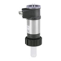
Burkert 8076 Operating Instructions Manual (180 pages)
Flow rate transmitter
Brand:
Burkert
| Category:
Transmitter
| Size: 7 MB
Table of Contents
English
5
Table of Contents
5
1 About this Manual
9
Symbols Used
9
2 Intended Use
10
Restraints
10
Foreseeable Misuse
10
3 Basic Safety Information
11
4 General Information
12
Contents of the Delivery
12
Warranty Conditions
12
Information on the Internet
12
Type 8026
12
5 Description
13
Area of Application
13
General Description
13
Construction of the 8026
13
Construction of the 8036
13
Construction of the 8076
14
Description of the Labels
14
Versions of the 8026 Available
14
Versions of the SE36 Electronic Module Available
15
6 Technical Data
16
Conditions of Use
16
Conforming to Standards and Directives
16
Conformities Common to the 8026 and the SE36
16
Conformity to the Pressure Directive of 8026 Transmitters and S030 and S070 Fittings
16
General Technical Data
16
Mechanical Data
16
General Data
20
Electrical Data
21
7 Assembly
22
Safety Instructions
22
Unscrew the Cover
22
Fitting the Cover
22
Fitting the Display Module (Available as an Accessory)
23
Removing the Display Module (Available as an Accessory)
23
8 Installation and Wiring
25
Safety Instructions
25
Installation Onto the Pipe
25
Recommendations on Installing an 8026 or an 8036 on a Pipe
25
Recommendations on Installing an 8076 on a Pipe
27
Electrical Wiring
27
Electrical Connections
27
Assembling the Male or Female Connector (Accessories: See Chap. 12)
28
Wiring a Version with an M12 Fixed Connector and an NPN Transistor Output and a Current Output
28
Wiring a Version with One M12 Fixed Connector and Two Transistor Outputs and a Current Output
29
Wiring a Version with Two M12 Fixed Connectors and Two Transistor Outputs and Two Current Outputs
31
9 Commissioning
34
Safety Instructions
34
10 Adjustment and Functions
35
Safety Instructions
35
Functions
35
Using the Browse Button
36
Example of a Numerical Value Input
38
Example of Browsing in a Menu
38
Description of the Display
39
Description of the Icons and Leds
39
When Switching on the Device
40
Read Mode
40
Programming Mode Access
41
Structure of the Programming Menus
42
Parameters Menu ("Param")
45
Transfer Certain Data from One Device to Another (Menu "System" - Function "Up/Download")
45
Modify the PARAM Menu Access Code (Menu "System" - Function "Code")
46
Restore the Default Parameters for Read Mode and Outputs (Menu "System" - Function "Factory Set")
46
Set the Parameters of the Data Displayed on Lines 1 and 2 in the Display Module (Menu "Display" - Functions "Line1" and "Line2")
46
Choose the Units for the Totalisers Displayed in Read Mode (Menu "Display" - Function "Totalisers")
48
Set the Parameters for the Display of the Minimum and Maximum Values Measured (Menu "Display" - Function "Min/Max")
48
Set the Parameters for the Reading Comfort Level of the Data Displayed ("Display" Menu)
48
Define the Output Connection Mode (Menu "Outputs" - Function "Hwmode")
49
Setting the Parameters for the Current Outputs (Menu "Outputs" - Functions "AC1" and "AC2")
49
Set the Parameters for the Transistor Outputs (Menu "Outputs" - Functions "TR1" and "TR2")
51
Calibration Menu ("Calib")
53
Activate/Deactivate the Hold Function (Menu "System" - Function "Hold")
53
Modify the Calibration Menu Access Code (Menu "System" - Function "Code")
53
Reset Totaliser 1 or Totaliser 2 Respectively (Menu "System" - Functions "Total1" and "Total2")
53
Adjust the Current Outputs ("Outputs" Menu)
54
Input the K Factor or Determine It with Teach-In ("Sensor" Menu)
54
Diagnostic Menu ("Diagnostic")
57
Modify the Diagnostic Menu Access Code ("System" Menu)
57
Monitor the Sensor Input Frequency (Menu "Sensor" - Function "Frequency")
57
Test Menu ("Test")
58
Modify the Test Menu Access Code ("System" Menu)
58
Check that the Outputs Are Working Correctly ("Outputs" Menu)
58
Check that the Outputs Are Behaving Correctly ("Sensor" Menu)
59
Information Menu ("Info")
59
11 Maintenance and Troubleshooting
60
Safety Instructions
60
Cleaning of the Transmitter
60
If You Encounter Problems
60
12 Spare Parts and Accessories
62
13 Packaging, Transport
62
14 Storage
62
15 Disposal of the Device
62
Deutsch
63
1 Die Bedienungsanleitung
67
Darstellungsmittel
67
2 Bestimmungsgemässe Verwendung
68
Beschränkungen
68
Vorhersehbarer Fehlgebrauch
68
3 Grundlegende Sicherheitshinweise
69
4 Allgemeine Hinweise
70
Lieferumfang
70
Gewährleistung
70
Informationen IM Internet
70
5 Beschreibung
71
Vorgesehener Einsatzbereich
71
Allgemeine Beschreibung
71
Aufbau des 8026
71
Aufbau des 8036
71
Aufbau des 8076
72
Beschreibung der Produktetiketten
72
Lieferbare Versionen des 8026
72
Lieferbare Versionen des Elektronikmoduls SE36
73
6 Technische Daten
74
Betriebsbedingungen
74
Einhaltung von Normen und Richtlinien
74
Vom 8026 und SE36 Eingehaltene Normen
74
Einhaltung der Druckgeräterichtlinie durch die Transmitter 8026 und Fittings S030 und S070
74
Allgemeine Technische Daten
74
Mechanische Daten
74
Allgemeine Daten
78
Elektrische Daten
79
7 Montage
80
Sicherheitshinweise
80
Abschrauben des Deckels
80
Anbringen des Deckels
80
Einbau des Anzeigemoduls (als Zubehör Erhältlich)
81
Ausbau des Anzeigemoduls (als Zubehör Erhältlich)
81
8 Installation und Verkabelung
83
Sicherheitshinweise
83
Anschluss an die Leitung
83
Hinweise für die Installation eines 8026 oder eines 8036 an einer Rohrleitung
83
Empfehlungen für die Installation eines 8076 an einer Rohrleitung
85
Elektrische Verkabelung
85
Elektrische Anschlüsse
85
Bauen Sie den Stecker Bzw. die Buchse Zusammen (Zubehör: Siehe Kap. 12)
86
Verkabelung einer Version mit M12-Steckverbindung und einem NPN- Transistorausgang und einem Stromausgang
86
Verkabelung einer Version mit M12-Verbinder und Zwei Transistorausgängen und einem Stromausgang
87
Und 2 Stromausgängen
89
9 Inbetriebnahme
92
Sicherheitshinweise
92
10 Bedienung und Funktion
93
Sicherheitshinweise
93
Funktion
93
Die Verwendung des Navigationsknopfes
94
Beispiel für die Eingabe eines Numerischen Werts
96
Beispiel bei der Navigation in den Menüs
96
Beschreibung der Anzeige
97
Beschreibung der Symbole und Lichtanzeigen
97
Anzeige nach Anschluss der Elektrischen Spannung
98
Lesebetrieb
98
Zugriff auf den Programmierbetrieb
99
Struktur der Programmiermenüs
100
Menü Parametrierung ("Param")
103
Übertragen Bestimmter Daten von einem Gerät zu einem anderen (Menü "System" - Funktion "Up/Download")
103
Änderung des Codes zum Zugriff auf das Menü PARAM (Menü "System" - Funktion "Code")
104
Die Standardparameter des Lesebetriebs und der Ausgänge wieder Herstellen (Menü "System" - Funktion "Factory Set")
104
Die in den Zeilen 1 und 2 des Anzeigemoduls Angezeigten Daten Einstellen (Menü "Display" - Funktionen "Line1" und "Line2")
104
Die Einheiten der IM Lesemodus Angezeigten Summenzähler Wählen (Menü "Display" - Funktion "Totalizers")
106
Die Anzeige der Gemessenen Minimal- und Maximalwerte Parametrieren (Menü "Display" - Funktion "Min/Max")
106
Parametrierung des Lesekomforts der Angezeigten Daten (Menü "Display")
106
Anschlussweise der Ausgänge Definieren (Menü "Outputs" - Funktion "Hwmode")
107
Parametrierung der Stromausgänge (Menü "Outputs" - Funktionen "AC1" und "AC2")
107
Parametrierung der Transistorausgänge (Menü "Outputs" - Funktionen "TR1" und "TR2")
109
Menü Kalibrierung ("Calib")
111
Aktivierung / Deaktivierung Derfunktion Hold (Menü "System" - Funktion "Hold")
111
Änderung des Codes zum Zugriff auf das Menü Calibration (Menü "System" - Funktion "Code")
111
Summenzähler 1 Bzw. Summenzähler 2 auf Null Stellen (Menü "System" - Funktionen "Total1" und "Total2")
111
Einstellung der Stromausgänge (Menü "Outputs")
112
Den K-Faktor Eingeben oder Mittels Teach-In Bestimmen (Menü "Sensor")
112
Menü Diagnose ("Diagnostic")
115
Änderung des Codes zum Zugriff auf das Menü Diagnose (Menü "System")
115
Die Eingangsfrequenz des Sensors Überwachen (Menü "Sensor" - Funktion "Frequency")
115
Menü Test ("Test")
116
Änderung des Codes zum Zugriff auf das Menü Test (Menü "System")
116
Kontrolle der Ordnungsgemäßen Funktionsfähigkeit der Ausgänge (Menü "Out- Puts")
116
Kontrolle des Ordnungsgemäßen Verhaltens der Ausgänge (Menü "Sensor")
117
Menü Information ("Info")
117
11 Wartung, Fehlerhabung
118
Sicherheitshinweise
118
Die Pflege des Transmitters
118
Problemlösung
118
12 Ersatzteile, Zubehör
120
13 Verpackung, Transport
120
14 Lagerung
120
15 Entsorgung
120
Français
121
1 A Propos de Ce Manuel
125
Symboles Utilisés
125
2 Utilisation Conforme
126
Restrictions
126
Mauvaise Utilisation Prévisible
126
3 Consignes de Sécurité de Base
127
4 Informations Générales
128
Contenu de la Livraison
128
Conditions de Garantie
128
Informations Sur Internet
128
5 Description
129
Secteur D'application
129
Description Générale
129
Construction du 8026
129
Construction du 8036
129
Construction du 8076
130
Description des Étiquettes Produit
130
Versions Disponibles du 8026
130
Versions Disponibles du Module Électronique SE36
131
6 Caractéristiques Techniques
132
Conditions D'utilisation
132
Conformité Aux Normes Et Directives
132
Conformités Communes Aux 8026 Et SE36
132
Conformité À la Directive Pression des Transmetteurs 8026 Et des Raccords S030 Et S070
132
Caractéristiques Techniques Générales
132
Caractéristiques Mécaniques
132
Caractéristiques Générales
136
Caractéristiques Électriques
137
7 Assemblage
138
Consignes de Sécurité
138
Dévisser Le Couvercle
138
Mettre en Place Le Couvercle
139
Mettre en Place Le Module D'affichage (Disponible en Accessoire)
139
Démonter Le Module D'affichage (Disponible en Accessoire)
140
8 Installation Et Câblage
141
Consignes de Sécurité
141
Installation Sur la Canalisation
141
Recommandations D'installation D'un 8026 Ou D'un 8036 Sur Une Canalisation
141
Recommandations D'installation D'un 8076 Sur Une Canalisation
143
Câblage Électrique
143
Raccordements Électriques
143
Assembler Le Connecteur Mâle Ou Femelle (Accessoires : Voir Chap. 12)
144
Câbler Une Version Avec Une Embase M12 Et Deux Sorties Transistor Et Une Sortie Courant
145
Câbler Une Version Avec Deux Embases M12 Et Deux Sorties Transistor Et Deux Sorties Courant
147
9 Mise en Service
150
Consignes de Sécurité
150
10 Réglage Et Fonctionnalités
151
Consignes de Sécurité
151
Fonctionnalités
151
Utiliser Le Bouton de Navigation
152
Exemple de Saisie D'une Valeur Numérique
154
Exemple de Navigation Dans un Menu
154
Description de L'afficheur
155
Description des Icones Et des Voyants
155
A la Mise Sous Tension de L'appareil
156
Mode Lecture
156
Accès Au Mode Programmation
157
Structure des Menus de Programmation
158
Menu Paramétrage («Param»)
161
Transférer Certaines Données D'un Appareil À L'autre (Menu «System» - Fonction «Up/Download»)
161
Modifier Le Code D'accès Au Menu PARAM (Menu «System» - Fonction «Code»)
162
Rétablir Les Paramètres Par Défaut du Mode Lecture Et des Sorties (Menu «System» - Fonction «Factory Set»)
162
Paramétrer Les Données Affichées Sur Les Lignes 1 Et 2 du Module D'affichage (Menu «Display» - Fonctions «Line1» Et «Line2»)
162
Choisir Les Unités des Totalisateurs Affichés Dans Le Mode Lecture (Menu «Display» - Fonction «Totalizers»)
164
Paramétrer L'affichage des Valeurs Minimum Et Maximum Mesurées (Menu «Display» - Fonction «Min/Max»)
164
Paramétrer Le Confort de Lecture des Données Affichées (Menu «Display»)
164
Définir Le Mode de Raccordement des Sorties (Menu «Outputs» - Fonction «Hwmode»)
165
Paramétrer Les Sorties Courant (Menu «Outputs» - Fonctions «AC1» Et «AC2»)
165
Paramétrer Les Sorties Transistor (Menu «Outputs» - Fonctions «TR1» Et «TR2»)
167
Menu Calibration («Calib»)
169
Activer/Désactiver la Fonction Hold (Menu «System» - Fonction «Hold»)
169
Modifier Le Code D'accès Au Menu Calibration (Menu «System» - Fonction «Code»)
169
Remettre À Zéro Le Totalisateur 1 Resp. Le Totalisateur 2 (Menu «System» - Fonctions «Total1» Et «Total2»)
169
Ajuster Les Sorties Courant (Menu «Outputs»)
170
Saisir Le Facteur K Ou Le Déterminer Par Teach-In (Menu «Sensor»)
170
Menu Diagnostic („Diagnostic")
173
Modifier Le Code D'accès Au Menu Diagnostic (Menu «System»)
173
Surveiller la Fréquence D'entrée du Capteur (Menu «Sensor» - Fonction «Frequency»)
173
Menu Test („Test")
174
Modifier Le Code D'accès Au Menu Test (Menu «System»)
174
Vérifier Le Bon Fonctionnement des Sorties (Menu «Outputs»)
174
Advertisement
burkert 8076 Quick Start Manual (128 pages)
Flowmeters with paddle wheel
Brand:
burkert
| Category:
Measuring Instruments
| Size: 3 MB
Table of Contents
English
2
Table of Contents
2
About The Quickstart
3
Intended Use
4
Basic Safety Information
4
General Information
6
Description Of The Name Plate
6
Technical Data
7
English
13
Installation And Wiring
17
Adjustment And Commissioning
27
Maintenance And Troubleshooting
40
Packaging, Transport
40
Disposal Of The Product
41
Deutsch
44
Über Den Quickstart
45
Bestimmungsgemässe Verwendung
46
Grundlegende Sicherheitshinweise
46
Allgemeine Hinweise
48
Beschreibung Des Typenschilds
49
Technische Daten
49
Installation Und Verkabelung
59
Bedienung, Inbetriebnahme
69
Verpackung, Transport
82
Wartung, Fehlerbehebung
82
Entsorgung
83
Type 8026
85
Français
86
À Propos Du Quickstart
87
Consignes De Sécurité De Base
88
Utilisation Conforme
88
Description De L'étiquette D'identification
90
Informations Générales
90
Caractéristiques Techniques
91
Installation Et Câblage
101
Réglage Et Mise En Service
111
Emballage Et Transport
124
Maintenance Et Dépannage
124
Élimination De L'appareil
125
Burkert 8076 Operating Instructions Manual (72 pages)
Flowmeters and Flow transmitters
Brand:
Burkert
| Category:
Measuring Instruments
| Size: 2 MB
Table of Contents
Operating Instructions
1
Table of Contents
3
1 About this Manual
6
Symbols Used
6
Definition Of The Word "Device
6
2 Intended Use
7
3 Basic Safety Information
8
4 General Information
10
Manufacturer's Address And International Contacts
10
Warranty Conditions
10
Information On The Internet
10
5 Description
11
Area Of Application
11
General Description
11
Construction of the 8026
11
Construction of the 8036
12
Construction of the 8076
12
Description Of The Name Plate
13
Available Versions Of Type 8026
14
Available Versions Of The Electronic Module Se36
15
6 Technical Data
16
Conditions Of Use
16
Conformity To Standards And Directives
16
Conformities Common to the 8026 and the SE36
16
Conformity to the Pressure Directive of Flowmeters 8026 and Fittings S030 and S070
16
General Technical Data
17
Mechanical Data
17
General Data
20
Electrical Data
21
7 Assembly
23
Safety Instructions
23
Unscrewing The Cover
23
Mounting The Cover
24
Mounting The Display Module
24
Dismounting The Display Module
25
8 Installation and Wiring
26
Safety Instructions
26
Installation Onto The Pipe
26
Recommendations on Installing an 8026 or an 8036 on a Pipe
27
Recommendations on Installing an 8076 on a Pipe
28
Wiring
29
Electrical Connections
29
Assembling the Male or Female Connector
29
Equipotentiality of the Installation
30
Wiring a Version with a Single M12 Fixed Connector and an NPN Transistor Output and a Current Output
31
Wiring a Version with a Single M12 Fixed Connector and Two Transistor Outputs and One Current Output
32
Wiring a Version with Two M12 Fixed Connectors and Two Transistor Outputs and Two Current Outputs
34
9 Adjustment and Commissioning
37
Safety Instructions
37
When Switching On The Device
37
Operating Levels
38
Using The Navigation Button
39
Using The Dynamic Functions
40
Example For The Input Of A Numerical Value
41
Example For Browsing In A Menu
41
Description Of Icons And Leds
42
Process Level
43
Accessing The Configuration Level
44
Structure Of The Configuration Menus
45
Parameters Menu
48
Transferring Data From One Device To Another
48
Modifying The Param Menu Access Code
50
Restoring The Default Parameters Of The Process Level And The Outputs
50
Setting The Data Displayed On Lines 1 And 2 Of The Display Module
50
Choosing The Units For The Totalizers Displayed In Process Level
52
Displaying The Lowest And Highest Values Measured
52
Setting The Parameters For The Reading Comfort Level Of The Data Displayed
53
Defining The Connection Mode Of The Outputs
53
Setting The Parameters Of The Current Outputs
53
Setting The Parameters Of The Transistor Outputs
55
Calibration Menu
57
Activating/Deactivating The Hold Function
57
Modifying The Calibration Menu Access Code
57
Resetting Totalizer 1 Or Totalizer 2 Respectively
58
Adjusting The Current Outputs
58
Entering The K Factor Or Determining It With Teach-In
59
Diagnostic Menu
62
Modifying The Diagnostic Menu Access Code
62
Monitoring The Sensor Input Frequency
62
Test Menu
63
Modifying The Test Menu Access Code
63
Checking The Outputs Functions
63
Checking The Outputs Behaviour
64
Information Menu
64
10 Maintenance and Troubleshooting
65
Safety Instructions
65
Cleaning The Device
65
If You Encounter Problems
65
11 Spare Parts and Accessories
68
12 Packaging, Transport
68
13 Storage
68
14 Disposal of the Product
69
Advertisement
Burkert 8076 Quick Start Manual (100 pages)
Flow rate transmitter
Brand:
Burkert
| Category:
Transmitter
| Size: 4 MB
Table of Contents
English
2
Table of Contents
2
About the Quickstart
3
Symbols Used
3
Intended Use
4
Basic Safety Information
5
Contents of the Delivery
6
Description
6
Technical Data
7
Installation and Wiring
12
Commissioning
19
Adjustment and Functions
20
Maintenance and Troubleshooting
28
Spare Parts and Accessories
31
Packaging, Transport, Storage
31
Disposal of the Device
32
Deutsch
34
Der Quickstart
35
Bestimmungsgemässe Verwendung
36
Grundlegende Sicherheitshinweise
37
Beschreibung
38
Lieferumfang
38
Technische Daten
39
Installation und Verkabelung
44
Inbetriebnahme
51
Bedienung und Funktion
52
Wartung, Fehlerhabung
60
Ersatzteile, Zubehör
63
Entsorgung
64
Français
66
Ce Quickstart
67
Symboles Utilisés
67
Utilisation Conforme
68
Consignes de Sécurité de Base
69
Contenu de la Livraison
70
Description
70
Caractéristiques Techniques
71
Installation Et Câblage
76
Mise en Service
83
Réglage Et Fonctionnalités
84
Maintenance Et Depannage
92
Emballage, Transport Et Stockage
95
Pièces de Rechange Et Accessoires
95
Elimination de L'appareil
96
Advertisement
Related Products
Burkert 8072
Burkert 8077
Burkert 8026
Burkert 8011
Burkert 8032
Burkert Flowave 8098
Burkert 8024
Burkert 8020
Burkert 8030-SE30 Series
Burkert 8071
Burkert Categories
Control Unit
Controller
Measuring Instruments
Transmitter
Accessories
More Burkert Manuals
Login
Sign In
OR
Sign in with Facebook
Sign in with Google
Upload manual
Upload from disk
Upload from URL