Sign In
Upload
Manuals
Brands
Brooks Manuals
Controller
GF Series
Brooks GF Series Manuals
Manuals and User Guides for Brooks GF Series. We have
2
Brooks GF Series manuals available for free PDF download: Installation And Operation Manual, Supplemental Manual
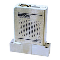
Brooks GF Series Installation And Operation Manual (62 pages)
High Performance Gas Flow Controllers
Brand:
Brooks
| Category:
Controller
| Size: 2 MB
Table of Contents
Table of Contents
5
Section 1 General Information
9
GF1XX Series High Performance Gas Flow Controller Analog and Digital
9
Notice and Caution Statements
10
Product Warranty
10
How to Order an Gf1Xx Device
10
Industry Standard References
10
GF1XX Gas Table
10
Glossary of Terms and Acronyms
11
Patents
12
Introduction
12
General Description
13
Intended Use
9
Introduction
9
Product Support References
9
Section 2 Product Description
12
GF1XX General Description
13
LED Display
13
Operating Principles
14
Specifications for GF Series Controller
15
Specifications for GF120XSD Series Controller
16
Specifications for GF120XSL Series Controller
16
Product Labeling
16
Mode Code Description
17
Standard Features
18
Mounting Attitude
18
Factory Setup Conditions
18
Calibration Traceability
18
Materials
18
Auto Shut-Off
19
LED Display
19
Optional Features
20
Control Valve Options
20
Flow Direction Option
20
Fittings Option
20
I/O Communication
20
Cable Connector Options
20
Section 3 Installation Instructions
21
Introduction
21
Flow Controller Installation Arrangement
21
Typical Gas Supply Arrangement with Non-PTI MFC
21
Typical Gas Supply Arrangement with PTI MFC
21
Purge the Gas Supply Line before GF1XX Installation
22
Unpack and Inspect the GF1XX Device
23
Position and Mount the GF1XX Device
23
GF1XX Mounting Attitude Positions
23
GF1XX Mounted to K1 Series Substrate Blocks
24
Perform a Leak Test
25
Mounting Screws Torque Pattern
25
Section 4 Multiflo Configurator
27
Introduction
27
Multiflo Configurator
27
Configure the Gas and Flow Range
28
Multiflo Cable Adapter
28
Diagnostic Port
28
Section 5 Performance Checks
29
Introduction
29
Zeroing Setup Process
29
Zeroing the GF1XX
30
Zeroing the GF1XX Pressure Transdcer from the LCD Display Panel
30
Display with PSI Reading
30
Zeroing the GF1XX Flow from LCD Display Panel
31
Display Reading Zero PSI
31
Display Set to %FS
31
Flow Display Set to Zero
31
Section 6 Maintenance Requirements
33
Introduction
33
Routine Maintenance
33
Factory Calibration and Service
34
On-Site Service
34
Section 7 System Troubleshooting
35
Introduction
35
OEM Tool Troubleshooting Checklist
35
Environmental Factors
35
GF1XX Troubleshooting Guide
36
Section 8 GF Series Device Removal and Return Instructions
41
Introduction
41
Purge Gas Lines before Removing the GF1XX
41
Remove and Replace the GF1XX
41
Package the GF1XX
42
Return Shipment of the GF1XX
42
Appendix A: Product Description Code
43
GF125 Product Description Code Table
43
GF100 Product Description Code Table
44
GF120 Product Description Code Table
45
Appendix B: Industry Standard References
49
Industry Standard References
50
Appendix C: GF Series Gas Table
51
GF1XX Gas Table
51
Appendix D: Misc. Drawings
55
Electrical Connections
55
D-1-1 Devicenet Connector
55
Dimensional Drawings
59
Advertisement
Brooks GF Series Supplemental Manual (54 pages)
EtherCAT Mass Flow Controllers and Meters
Brand:
Brooks
| Category:
Measuring Instruments
| Size: 1 MB
Table of Contents
Table of Contents
5
General Information
9
Introduction
9
Definition of Terms
10
Numbers
10
Table 1-1 - Definition of Terms
10
Quick Start
11
Master Hardware
11
Physical Interfaces
12
Power Supply
12
Figure 2-1 - Top View of GF Ethercat Device
12
Leds
13
Figure 2-2 - M8 Power Connector Location
13
Figure 2-3 - M8 Power Connector Drawing
13
Table 2-1 - RUN Indicator States
14
Table 2-2 - ERROR Indicator States
14
Exceptions Display Codes and Reporting
15
Table 2-3 - Display Code Summary
15
Slave Configuration
17
Introduction
17
Table 3-1 - Object Dictionary Structure
17
Process Data Object (PDO) Mapping
18
Rxpdo Mapping
18
Txpdo Mapping
19
Table 3-2 - Default Rxpdo (MFC/EMFC Profiles)
19
Table 3-3 - Default Rxpdo (MFM/EMFM Profiles)
19
Table 3-4 - Default Txpdo (EMFC Profile)
19
Table 3-5 - Default Txpdo (MFC Profile)
20
Table 3-6 - Default Txpdo (MFM Profile)
20
Table 3-7 - Default Txpdo (EMFM Profile)
20
Communication Specific Data
21
Table 3-8 - Communication Specific Data
21
Manufacturer Specific Data
22
Manufacturer Specific Inputs
23
Manufacturer Specific Configuration Data
23
Table 3-9 - Manufacturer Specific Inputs
23
Table 3-10 - Manufacturer Specific Configuration Data
23
SDP Device Type Specific Data
24
Input Data
24
Table 3-11 - Input Data
24
Output Data
25
Table 3-12 - Output Data
25
Configuration Data
26
Table 3-13 - Configuration Data
26
Information Data
27
Table 3-14 - Information Data
27
Semi Device Profile Area
29
Table 3-15 - Semi Device Profile
29
Value Range Setting
30
Exception Handling Data
30
Table 3-16 - Value Range Setting
30
Manufacturer Specific Device Data
32
Table 3-17 - Manufacturer Specific Device Data
32
SDP and CDP Device Specific Inputs
33
SDP and CDP Device Specific Information Data
33
Table 3-18 - SDP and CDP Device Specific Inputs
33
Table 3-19 - SDP and CDP Device Specific Information Data
33
SDP and CDP Command Objects
35
Table 3-20 - SDP and CDP Command Objects
35
Exceptions Implementation
41
Table 4-1 - Objects for Reporting and Controlling Exceptions
42
Table 4-2 - Device Errors
43
Table 4-3 - Manufacturer Errors
43
Error and Warning Condition Descriptions
44
Table 4-4 - Manufacturer Warnings
44
Non-Volatile Memory Failures (Display Codes 1,2,3)
45
Network Interface Failure (Display Code 4)
45
Selected Calibration Invalid (Display Code 5)
45
Identity Information Mismatch (Display Code 6)
45
Hardware Incompatibility (Display Code 7)
46
Flow Sensor Failure & Error (Display Code 10 and 110)
46
Flow Sensor Cooling Recovery (Display Code 111)
46
Excessive Drift (Display Code 112)
46
Process Flow out of Range (Display Codes 115 and 116)
46
Table 4-5 - User Specified Flow Limits
46
Pressure Sensor Error (Display Code 120)
47
Process Pressure out of Range (Display Codes 125 and 126)
47
Temperature Sensor Failure & Error (Display Code 130 and 10)
47
Table 4-6 - User Specified Pressure Limits
47
Temperature out of Range (Display Codes 135 and 136)
48
Excessive Leak-By (Display Code 142)
48
Control Deviation out of Limits (Display Code 145)
48
Table 4-7 - Control Deviation out of Limits
48
Temperature Stability (Display Code 230)
49
Mounting Orientation Alert (Display Code 251)
49
Voltage Input out of Limits (Display Code 260)
49
Totalizer Overflow Alert (Display Code 270)
49
Warm-Up (Display Code 299)
49
Device ID Switch Changed Alert (no Display Code)
50
Appendix
51
Ramping Feature
51
Figure 5-1 - Ramping Feature
52
Advertisement
Related Products
Brooks GF100 Series
Brooks GF1 Series
Brooks GF120XSD Series
Brooks GF120XSL Series
Brooks GF120 Series
Brooks GP200
Brooks GF125
Brooks GF121
Brooks GF135
Brooks GF101
Brooks Categories
Measuring Instruments
Controller
Laboratory Equipment
Security System
Robotics
More Brooks Manuals
Login
Sign In
OR
Sign in with Facebook
Sign in with Google
Upload manual
Upload from disk
Upload from URL