Sign In
Upload
Manuals
Brands
AirSep Manuals
Oxygen Equipment
AS-P
AirSep AS-P Manuals
Manuals and User Guides for AirSep AS-P. We have
2
AirSep AS-P manuals available for free PDF download: Instruction Manual
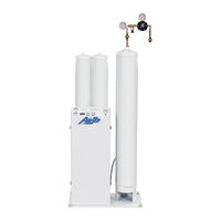
AirSep AS-P Instruction Manual (193 pages)
PSA Oxygen Generator
Brand:
AirSep
| Category:
Oxygen Equipment
| Size: 24.64 MB
Table of Contents
Airsep Representative
3
PSA Oxygen Generator
3
Table of Contents
5
List of Illustrations
7
1 Introduction
9
General
9
Warnings, Cautions, and Notes
9
References to Controls and Indicators with Tags or Labels
10
2 Safety
11
Potential Hazards
11
General
11
Safety Publications
12
3 System Description
15
General
15
4 Components Description
17
External Components
17
External Components — Front View
17
Figure 4.1: External Components - Front View
17
Adsorbers
18
Enclosure
18
Fuse Holder
18
Power Cord
18
Control Panel
19
Oxygen Outlet
19
Condensate Drain Outlet
19
On/Off Switch
19
Figure 4.2: Control Panel - AS-B and AS-D Models
19
Hour Meter (Not Available on AS-A Models)
20
Manifold Components
20
Manifold Components — AS-B Model
20
Figure 4.3: Manifold Components - AS-B Model
20
Manual Inlet Valve
21
Figure 4.4: Manifold Components - AS-L Model
21
Coalescing Filter
22
Feed Air Regulator
22
Filter Drain Valve
22
Particulate Filter (Not Available on AS-A Models)
22
Circuit Board/Plc
23
Pressure Switch
23
Relief Valves
23
Transformer
23
Accessory Kits
24
Air Hose
25
Regulator Kit/Assembly
25
Oxygen Hose
25
Magnalube-G
25
Additional Available Accessories
26
5 Installation
27
Handling and Unpacking
27
Pre-Installation Guidelines
28
Installation Instructions
29
Feed Air Connection Sizes and Hose Sizes
29
Figure 5.1: Typical Installation Arrangement
29
Oxygen Outlet Connection Sizes
30
6 Operation
33
Initial Start-Up
33
Shutdown
35
Normal Start-Up
35
Extended Shutdown
36
Start-Up after an Extended Shutdown
36
7 Maintenance
37
Daily Monitoring
37
Monthly Monitoring
37
Maintenance Chart
37
Removing the Front Cover of the Enclosure
38
Depressurizing the Filters
39
Figure 7.1: Interior View of AS-B Model
39
Changing Filter Elements
40
Depressurizing the Oxygen Generator
41
Adjusting the Feed Air Regulator
42
Adjusting the Pressure Switch
43
AS-A – AS-D Oxygen Generators
43
Signal Setting Chart
44
Figure 7.2: Pressure Switch for AS-A - AS-D
44
AS-D+ - AS-P Oxygen Generators
45
Technical Support
49
Troubleshooting Chart
49
Specifications
53
Figure A.1: Typical Pressure Profile and Valves Cycle Sequence
69
Figure A.2: Typical Installation Arrangement
70
Figure A.3: General Arrangement Drawing - AS-A
71
Flow Schematic – AS-A
72
Figure A.4: Flow Schematic - AS-A
72
Electrical Schematic – AS-A (120 V)
73
Figure A.5: Electrical Schematic - AS-A (120 V
73
Electrical Schematic – AS-A (240 V)
74
Figure A.6: Electrical Schematic - AS-A (240 V
74
Figure A.7: General Arrangement Drawing - AS-B
75
Figure A.8: General Arrangement Drawing - AS-D
76
Figure A.9: Flow Schematic - AS-B and AS-D
77
Electrical Schematic – AS-B and AS-D (120 V)
78
Figure A.10: Electrical Schematic - AS-B and AS-D (120 V
78
Electrical Schematic – AS-B and AS-D (240 V)
79
Figure A.11: Electrical Schematic - AS-B and AS-D (240 V
79
General Arrangement Drawing – AS-D+
80
Figure A.12: General Arrangement Drawing - AS-D
80
Flow Schematics – AS-D+
81
Figure A.13: Flow Schematics - AS-D
81
Figure A.14: General Arrangement Drawing - AS-E
82
Flow Schematic – AS-E
83
Figure A.15: Flow Schematic - AS-E
83
Figure A.16: General Arrangement Drawing - AS-G
84
Flow Schematic – AS-G
85
Figure A.17: Flow Schematic - AS-G
85
Figure A.18: General Arrangement Drawing - AS-J
86
Flow Schematic – AS-J
87
Figure A.19: Flow Schematic - AS-J
87
Figure A.20: General Arrangement Drawing - AS-K
88
Flow Schematic – AS-K
89
Figure A.21: Flow Schematic - AS-K
89
Figure A.22: General Arrangement Drawing - AS-L
90
Flow Schematic – AS-L
91
Figure A.23: Flow Schematic - AS-L
91
Figure A.24: General Arrangement Drawing - AS-N
92
Flow Schematic – AS-N
93
Figure A.25: Flow Schematic - AS-N
93
Figure A.26: General Arrangement Drawing - AS-P
94
Flow Schematic – AS-P
95
Figure A.27: Flow Schematic - AS-P
95
Figure A.28: Electrical Schematic - AS-D+ Thru AS-P - I
96
Electrical Schematic – AS-D+ Thru AS-P – II
97
Electrical Schematic – AS-D+ Thru AS-P – III
98
A Appendix Technical Data
99
B Appendix Warranty/Returns
99
Returning the Oxygen Generator or a Component for Service
100
Parts List
103
Component Literature
115
Programmable Relay
119
Enhanced Features
120
Other Versatile Functions
120
Analog Input
120
Twin-Timer Operation Added
120
Series Configuration
121
CPU Units
121
Expansion I/O Units
121
Power Supply Unit
121
Ratings
122
Warning
127
Important Maintenance
127
Microalescer Filter
129
Installation and Maintenance Sheet
133
Typical Installation
133
Repair Kits and Replacement Parts
133
General Information
145
Model Designation
145
Schematic
145
Principle of Operation
145
Capacity
146
Flow Capacity Formulas
146
Needle Valve Sizing
146
Flow Range Examples
146
Assembly of Switch and Transducer Units
153
Temperature Limitations
153
Positioning
153
Piping/Tubing
154
Direct Probe
154
Capillary and Bulb
154
Electrical Ratings
154
Preventive Maintenance
155
Causes of Improper Operation
155
Testing of Installation
155
Ordering Information
155
Adjustment of Limited Adjustable Deadband Switch
156
Open-Frame Switch Unit and Transducer Unit to be Assembled
156
UL Listings
158
Pressure Controls
159
Contact Ratings
159
Standard Contact Arrangement for Positive Pressure
159
Operating Range Adjustment
160
Differential Adjustment
160
Pilot Light Option
160
Bellows Life
160
Required Fastener Torque
163
Parts
163
Service Kits
164
Stem Nut Torque
164
Valve Size
164
Future Service Considerations
165
Push Type Manual Operator
165
Screw Type Manual Operator
165
Flow Metering Devices
165
Valve Reassembly
166
Piping
166
Valve Disassembly
166
Torque Chart
167
Disassembly and Reassembly of Stem/Lever Type Manual Operator
168
Stem/Lever Type Manual Operators
168
Advertisement
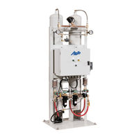
AirSep AS-P Instruction Manual (198 pages)
PSA Oxygen Generators (with touchscreen)
Brand:
AirSep
| Category:
Portable Generator
| Size: 22.95 MB
Table of Contents
Table of Contents
5
1 Introduction
11
General
11
Warnings, Cautions, and Notes
11
References to Controls and Indicators with Tags or Labels
11
2 Safety
13
General
13
Potential Hazards
13
Safety Publications
14
3 System Description
15
General
15
4 Components Description
17
External Components
17
Adsorbers
18
Connections
18
Manifold Components
19
Control Panel: External Components
21
Control Panel: Internal Components
28
Accessory Kits
29
5 Installation
33
Handling and Unpacking
33
Pre-Installation Guidelines
34
Installation Instructions
35
Initial Start-Up
38
Operation
40
Shutdown
40
Extended Shutdown
41
Start-Up after an Extended Shutdown
41
6 Maintenance
43
Daily Monitoring
43
Monthly Monitoring
43
Depressurizing the Filters
44
Changing Filter Elements
45
Depressurizing the Oxygen Generator
46
Adjusting the Feed Air Regulator
46
7 Troubleshooting
49
Technical Support
49
Troubleshooting Chart
49
Appendix Technical Data
55
Specifications
55
Drawings and Schematics
65
Electrical Schematics - As-D+ - As-P
83
Appendix Warranty/Returns
87
Product Warranty
87
Limits of Liability
88
Returning the Oxygen Generator or a Component for Service
88
Appendix Component Literature
91
Programmable Logic Controller
91
Touchscreen
108
Filters
116
Regulators
129
Valves
133
Advertisement
Related Products
AirSep AS-B
AirSep AS-D
AirSep AS-E
AirSep AS-J
AirSep AS-K
AirSep AS-80
AirSep AS-450
AirSep AS-1000
AirSep AS-D+
AirSep AS-G
AirSep Categories
Medical Equipment
Oxygen Equipment
Portable Generator
Air Compressor
Analytical Instruments
More AirSep Manuals
Login
Sign In
OR
Sign in with Facebook
Sign in with Google
Upload manual
Upload from disk
Upload from URL