Sign In
Upload
Manuals
Brands
Agilent Technologies Manuals
Test Equipment
InfiniiVision MSO-X 2012A
Agilent Technologies InfiniiVision MSO-X 2012A Manuals
Manuals and User Guides for Agilent Technologies InfiniiVision MSO-X 2012A. We have
2
Agilent Technologies InfiniiVision MSO-X 2012A manuals available for free PDF download: User Manual
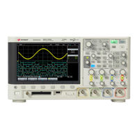
Agilent Technologies InfiniiVision MSO-X 2012A User Manual (352 pages)
Brand:
Agilent Technologies
| Category:
Test Equipment
| Size: 6.58 MB
Table of Contents
Safety Notices
2
Infiniivision 2000 X-Series Oscilloscopes-At a Glance
3
In this Guide
5
Getting Started
21
Inspect the Package Contents
21
Install the Optional LAN/VGA or GPIB Module
24
Tilt the Oscilloscope for Easy Viewing
24
Power-On the Oscilloscope
25
Connect Probes to the Oscilloscope
26
Maximum Input Voltage at Analog Inputs
26
Do Not Float the Oscilloscope Chassis
26
Input a Waveform
27
Recall the Default Oscilloscope Setup
27
Use Auto Scale
28
Compensate Passive Probes
29
Learn the Front Panel Controls and Connectors
30
Table of Contents
5
0 Chapter 3, “Vertical Controls,” Starting on Page 59
32
0 Chapter 4, “Math Waveforms,” Starting on Page 67
32
0 Chapter 5, “Reference Waveforms,” Starting on Page
32
0 Chapter 6, “Digital Channels,” Starting on Page 85
32
0 Chapter 7, “Serial Decode,” Starting on Page 15
32
0 Chapter 8, “Display Settings,” Starting on Page 111
32
0 Chapter 9, “Labels,” Starting on Page 117
32
0 Chapter 12, “Acquisition Control,” Starting on Page 153
32
0 Chapter 14, “Measurements,” Starting on Page 179
32
0 Chapter 15, “Mask Testing,” Starting on Page 199
32
0 Chapter 16, “Digital Voltmeter,” Starting on Page 211
32
Starting on
32
Decode," Starting on
34
Vertical Controls," Starting on
36
Digital Channels," Starting on
37
Front Panel Overlays for Different Languages
37
Learn the Rear Panel Connectors
39
Learn the Oscilloscope Display
41
Access the Built-In Quick Help
42
Horizontal Controls
46
To Adjust the Horizontal (Time/DIV) Scale
46
To Adjust the Horizontal Delay (Position)
47
Panning and Zooming Single or Stopped Acquisitions
48
To Change the Horizontal Time Mode (Normal, XY, or Roll)
49
XY Time Mode
50
To Display the Zoomed Time Base
52
To Change the Horizontal Scale Knob's Coarse/Fine Adjustment Setting
54
To Position the Time Reference (Left, Center, Right)
54
Triggers," Starting on
55
Searching for Events
55
To Set up Searches
55
Navigating the Time Base
56
To Navigate Time
56
To Navigate Search Events
56
To Navigate Segments
57
Vertical Controls
60
To Turn Waveforms on or off (Channel or Math)
60
To Adjust the Vertical Position
61
To Adjust the Vertical Scale
61
To Specify Channel Coupling
61
To Change the Vertical Scale Knob's Coarse/Fine Adjustment Setting
62
To Specify Bandwidth Limiting
62
Setting Analog Channel Probe Options
63
To Invert a Waveform
63
To Specify the Channel Units
64
To Specify the Probe Attenuation
64
To Specify the Probe Skew
65
Math Waveforms
67
To Display Math Waveforms
67
To Perform a Transform Function on an Arithmetic Operation
68
To Adjust the Math Waveform Scale and Offset
69
Units for Math Waveforms
69
Add or Subtract
70
Math Operators
70
Multiply or Divide
71
FFT Measurement
72
Math Transforms
72
Reference Waveforms
81
To Save a Waveform to a Reference Waveform Location
81
To Display a Reference Waveform
82
To Adjust Reference Waveform Skew
83
To Scale and Position Reference Waveforms
83
To Display Reference Waveform Information
84
To Save/Recall Reference Waveform Files To/From a USB Storage Device
84
Digital Channels
86
Probe Cable for Digital Channels
86
To Connect the Digital Probes to the Device under Test
86
Acquiring Waveforms Using the Digital Channels
89
To Display Digital Channels Using Autoscale
89
Interpreting the Digital Waveform Display
90
To Change the Displayed Size of the Digital Channels
91
To Change the Logic Threshold for Digital Channels
92
To Switch a Single Channel on or off
92
To Switch All Digital Channels on or off
92
To Switch Groups of Channels on or off
92
To Reposition a Digital Channel
93
To Display Digital Channels as a Bus
94
Digital Channel Signal Fidelity: Probe Impedance and Grounding
97
Input Impedance
98
Probe Grounding
100
Best Probing Practices
102
To Replace Digital Probe Leads
102
Serial Decode
105
Serial Decode Options
105
Lister
106
Searching Lister Data
108
Display Settings
111
To Adjust Waveform Intensity
111
To Set or Clear Persistence
113
To Clear the Display
114
To Select the Grid Type
114
To Adjust the Grid Intensity
115
To Freeze the Display
115
Labels
117
To Turn the Label Display on or off
117
To Assign a Predefined Label to a Channel
118
To Define a New Label
119
To Load a List of Labels from a Text File You Create
120
To Reset the Label Library to the Factory Default
121
Triggers
123
Adjusting the Trigger Level
124
Edge Trigger
125
Forcing a Trigger
125
Pattern Trigger
128
Hex Bus Pattern Trigger
130
Pulse Width Trigger
131
Video Trigger
133
To Trigger on a Specific Line of Video
137
To Trigger on All Sync Pulses
138
To Trigger on a Specific Field of the Video Signal
139
To Trigger on All Fields of the Video Signal
140
To Trigger on Odd or Even Fields
141
Serial Trigger
143
Trigger Mode/Coupling
145
To Select the Auto or Normal Trigger Mode
146
To Select the Trigger Coupling
148
To Enable or Disable Trigger HF Reject
149
To Enable or Disable Trigger Noise Rejection
149
External Trigger Input
150
To Set the Trigger Holdoff
150
Maximum Voltage at Oscilloscope External Trigger Input
151
Acquisition Control
153
Running, Stopping, and Making Single Acquisitions (Run Control)
153
Aliasing
155
Overview of Sampling
155
Sampling Theory
155
Oscilloscope Bandwidth and Sample Rate
156
Oscilloscope Rise Time
157
Oscilloscope Bandwidth Required
158
Memory Depth and Sample Rate
159
Selecting the Acquisition Mode
159
Normal Acquisition Mode
160
Peak Detect Acquisition Mode
160
Averaging Acquisition Mode
163
Acquiring to Segmented Memory
165
High Resolution Acquisition Mode
165
Infinite Persistence with Segmented Memory
167
Navigating Segments
167
Saving Data from Segmented Memory
168
Segmented Memory Re-Arm Time
168
To Make Cursor Measurements
170
Cursor Examples
173
To Make Automatic Measurements
180
Measurements Summary
181
Snapshot All
183
Voltage Measurements
183
Amplitude
184
Maximum
184
Minimum
184
Peak-Peak
184
Top
185
Base
186
Overshoot
186
Preshoot
187
Average
188
DC Rms
188
Ac Rms
189
Period
191
Time Measurements
191
Frequency
192
Duty Cycle
193
Fall Time
193
Rise Time
193
Width
193
Delay
194
Phase
195
Measurement Thresholds
196
Measurement Window with Zoom Display
198
Mask Testing
199
To Create a Mask from a "Golden" Waveform (Automask)
199
Mask Test Setup Options
201
Mask Statistics
204
To Manually Modify a Mask File
205
Building a Mask File
208
How Is Mask Testing Done
210
Digital Voltmeter
211
To Select Generated Waveform Types and Settings
215
Waveform Generator
215
Waveform Generator
218
To Output the Waveform Generator Sync Pulse
218
To Specify the Expected Output Load
219
To Use Waveform Generator Logic Presets
219
To Add Modulation to the Waveform Generator Output
220
To Add Noise to the Waveform Generator Output
220
To Set up Amplitude Modulation (AM)
221
To Set up Frequency Modulation (FM)
223
To Set up Frequency-Shift Keying Modulation (FSK)
224
To Restore Waveform Generator Defaults
225
Save/Recall (Setups, Screens, Data)
227
Saving Setups, Screen Images, or Data
227
To Save BMP or PNG Image Files
229
To Save Setup Files
229
To Save CSV, ASCII XY, or bin Data Files
230
Length Control
231
To Save Lister Data Files
232
To Save Masks
233
To Save Reference Waveform Files to a USB Storage Device
233
To Enter File Names
234
To Navigate Storage Locations
234
Recalling Setups, Masks, or Reference Waveforms
235
To Recall Setup Files
235
To Recall Mask Files
236
To Recall Reference Waveform Files from a USB Storage Device
236
Performing a Secure Erase
237
Recalling Default Setups
237
Print (Screens)
239
To Print the Oscilloscope's Display
239
To Set up Network Printer Connections
240
To Specify the Print Options
242
To Specify the Palette Option
243
I/O Interface Settings
245
Utility Settings
245
Setting up the Oscilloscope's LAN Connection
246
To Establish a LAN Connection
247
Stand-Alone (Point-To-Point) Connection to a PC
248
File Explorer
249
Setting Oscilloscope Preferences
251
To Choose "Expand About" Center or Ground
251
To Disable/Enable Transparent Backgrounds
252
To Load the Default Label Library
252
To Set up the Screen Saver
252
To Set Autoscale Preferences
253
Setting the Oscilloscope's Clock
254
Setting the Rear Panel TRIG out Source
254
Performing Service Tasks
255
To Perform User Calibration
256
To Perform Hardware Self Test
258
To Clean the Oscilloscope
259
To Display Oscilloscope Information
259
To Display the User Calibration Status
259
To Perform Front Panel Self Test
259
To Check Warranty and Extended Services Status
260
To Contact Agilent
260
To Return the Instrument
260
Chapter
261
Configuring the [Quick Action] Key
261
Adding an Annotation
262
Web Interface
266
Accessing the Web Interface
266
Browser Web Control
267
Real Scope Remote Front Panel
268
Simple Remote Front Panel
269
Browser-Based Remote Front Panel
270
Remote Programming Via the Web Interface
271
Remote Programming with Agilent IO Libraries
272
Save/Recall
273
Saving Files Via the Web Interface
273
Recalling Files Via the Web Interface
274
Get Image
275
Identification Function
276
Instrument Utilities
276
Setting a Password
277
Specifications and Characteristics
281
Measurement Category
281
Reference
282
Oscilloscope Measurement Category
282
Measurement Category Definitions
282
Transient Withstand Capability
283
Maximum Input Voltage at Analog Inputs
283
Maximum Input Voltage at Digital Channels
283
Environmental Conditions
283
Probes and Accessories
284
Passive Probes
284
Differential Probes
285
Current Probes
285
Accessories Available
286
Loading Licenses and Displaying License Information
287
Licensed Options Available
287
Other Options Available
288
Upgrading to an MSO
288
Software and Firmware Updates
289
Binary Data (.Bin) Format
289
Binary Data in MATLAB
290
Binary Header Format
290
Example Program for Reading Binary Data
293
Examples of Binary Files
293
CSV and ASCII XY Files
296
CSV and ASCII XY File Structure
297
Minimum and Maximum Values in CSV Files
297
Acknowledgements
298
CAN/LIN Triggering and Serial Decode
299
Setup for CAN Signals
299
CAN Triggering
301
CAN Serial Decode
303
Interpreting CAN Decode
304
CAN Totalizer
305
Interpreting CAN Lister Data
306
Searching for CAN Data in the Lister
307
Setup for LIN Signals
307
LIN Triggering
309
LIN Serial Decode
311
Interpreting LIN Decode
312
Interpreting LIN Lister Data
313
Searching for LIN Data in the Lister
314
I2C/SPI Triggering and Serial Decode
315
Setup for I2C Signals
315
I2C Triggering
316
I2C Serial Decode
320
Interpreting I2C Decode
321
Interpreting I2C Lister Data
322
Searching for I2C Data in the Lister
323
Setup for SPI Signals
324
SPI Triggering
327
SPI Serial Decode
329
Interpreting SPI Decode
331
Interpreting SPI Lister Data
332
Searching for SPI Data in the Lister
332
UART/RS232 Triggering and Serial Decode
335
Setup for UART/RS232 Signals
335
UART/RS232 Triggering
337
UART/RS232 Serial Decode
339
Interpreting UART/RS232 Decode
341
UART/RS232 Totalizer
342
Interpreting UART/RS232 Lister Data
343
Searching for UART/RS232 Data in the Lister
343
Measurements," Starting on
261
Advertisement
Agilent Technologies InfiniiVision MSO-X 2012A User Manual (296 pages)
Brand:
Agilent Technologies
| Category:
Test Equipment
| Size: 5.93 MB
Table of Contents
Safety Notices
2
Infiniivision 2000 X-Series Oscilloscopes-At a Glance
3
Table of Contents
5
In this Guide
5
Getting Started
19
Inspect the Package Contents
19
Install the Optional LAN/VGA or GPIB Module
22
Tilt the Oscilloscope for Easy Viewing
22
Power-On the Oscilloscope
23
Connect Probes to the Oscilloscope
24
Do Not Float the Oscilloscope Chassis
24
Maximum Input Voltage at Analog Inputs
24
Input a Waveform
25
Recall the Default Oscilloscope Setup
25
Use Auto Scale
26
Compensate Passive Probes
27
Learn the Front Panel Controls and Connectors
28
Horizontal Controls," Starting on
31
Vertical Controls," Starting on
34
Digital Channels," Starting on
35
Front Panel Overlays for Different Languages
35
Learn the Rear Panel Connectors
37
Learn the Oscilloscope Display
38
Access the Built-In Quick Help
40
Horizontal Controls
44
To Adjust the Horizontal (Time/DIV) Scale
44
To Adjust the Horizontal Delay (Position)
45
Panning and Zooming Single or Stopped Acquisitions
46
To Change the Horizontal Time Mode (Normal, XY, or Roll)
47
XY Time Mode
48
To Display the Zoomed Time Base
50
To Change the Horizontal Scale Knob's Coarse/Fine Adjustment Setting
52
To Position the Time Reference (Left, Center, Right)
52
Navigating the Time Base
53
To Navigate Time
53
To Navigate Segments
53
Vertical Controls
56
To Turn Waveforms on or off (Channel or Math)
56
To Adjust the Vertical Scale
57
To Adjust the Vertical Position
57
To Specify Channel Coupling
57
To Specify Bandwidth Limiting
58
To Change the Vertical Scale Knob's Coarse/Fine Adjustment Setting
58
To Invert a Waveform
59
Setting Analog Channel Probe Options
59
To Specify the Channel Units
60
To Specify the Probe Attenuation
60
To Specify the Probe Skew
61
Math Waveforms
63
To Display Math Waveforms
63
To Perform a Transform Function on an Arithmetic Operation
64
To Adjust the Math Waveform Scale and Offset
65
Units for Math Waveforms
65
Math Operators
66
Add or Subtract
66
Multiply or Divide
67
Math Transforms
68
FFT Measurement
68
Reference Waveforms
77
To Save a Waveform to a Reference Waveform Location
77
To Display a Reference Waveform
78
To Scale and Position Reference Waveforms
79
To Adjust Reference Waveform Skew
79
To Display Reference Waveform Information
80
To Save/Recall Reference Waveform Files To/From a USB Storage Device
80
To Connect the Digital Probes to the Device under Test
81
Digital Channels
82
Probe Cable for Digital Channels
82
Acquiring Waveforms Using the Digital Channels
85
To Display Digital Channels Using Autoscale
85
Interpreting the Digital Waveform Display
86
To Change the Displayed Size of the Digital Channels
87
To Switch a Single Channel on or off
88
To Switch All Digital Channels on or off
88
To Switch Groups of Channels on or off
88
To Change the Logic Threshold for Digital Channels
88
To Reposition a Digital Channel
89
To Display Digital Channels as a Bus
90
Digital Channel Signal Fidelity: Probe Impedance and Grounding
93
Input Impedance
94
Probe Grounding
96
Best Probing Practices
98
To Replace Digital Probe Leads
98
Display Settings
101
To Adjust Waveform Intensity
101
To Set or Clear Persistence
103
To Clear the Display
104
To Select the Grid Type
104
To Adjust the Grid Intensity
105
To Freeze the Display
105
Labels
107
To Turn the Label Display on or off
107
To Assign a Predefined Label to a Channel
108
To Define a New Label
109
To Load a List of Labels from a Text File You Create
110
To Reset the Label Library to the Factory Default
111
Triggers
113
Adjusting the Trigger Level
114
Forcing a Trigger
115
Edge Trigger
115
Pattern Trigger
118
Hex Bus Pattern Trigger
120
Pulse Width Trigger
121
Video Trigger
123
To Trigger on a Specific Line of Video
127
To Trigger on All Sync Pulses
128
To Trigger on a Specific Field of the Video Signal
129
To Trigger on All Fields of the Video Signal
130
To Trigger on Odd or Even Fields
131
Trigger Mode/Coupling
135
To Select the Auto or Normal Trigger Mode
136
To Select the Trigger Coupling
138
To Enable or Disable Trigger Noise Rejection
139
To Enable or Disable Trigger HF Reject
139
To Set the Trigger Holdoff
140
External Trigger Input
140
Maximum Voltage at Oscilloscope External Trigger Input
141
Acquisition Control
143
Running, Stopping, and Making Single Acquisitions (Run Control)
143
Overview of Sampling
145
Sampling Theory
145
Aliasing
145
Oscilloscope Bandwidth and Sample Rate
146
Oscilloscope Rise Time
147
Oscilloscope Bandwidth Required
148
Memory Depth and Sample Rate
149
Selecting the Acquisition Mode
149
Normal Acquisition Mode
150
Peak Detect Acquisition Mode
150
Averaging Acquisition Mode
153
High Resolution Acquisition Mode
155
Acquiring to Segmented Memory
155
0 Chapter 3, “Vertical Controls,” Starting on Page 55
155
0 Chapter 4, “Math Waveforms,” Starting on Page 63
155
0 Chapter 5, “Reference Waveforms,” Starting on Page
155
0 Chapter 6, “Digital Channels,” Starting on Page 81
155
0 Chapter 7, “Display Settings,” Starting on Page 11
155
0 Chapter 8, “Labels,” Starting on Page 17
155
Chapter
155
Triggers," Starting on
156
Chapter
156
Navigating Segments
157
Infinite Persistence with Segmented Memory
157
Segmented Memory Re-Arm Time
158
Saving Data from Segmented Memory
158
Cursors
159
To Make Cursor Measurements
160
Cursor Examples
163
Measurements
169
To Make Automatic Measurements
170
Measurements Summary
171
Snapshot All
173
Voltage Measurements
173
Peak-Peak
174
Maximum
174
Minimum
174
Amplitude
174
Top
175
Base
176
Overshoot
176
Preshoot
177
Average
178
DC Rms
178
Ac Rms
179
Time Measurements
181
Period
181
Frequency
182
Width
183
Duty Cycle
183
Rise Time
183
Fall Time
183
Delay
184
Phase
185
Measurement Thresholds
186
Measurement Window with Zoom Display
188
Mask Testing
189
To Create a Mask from a "Golden" Waveform (Automask)
189
Mask Test Setup Options
191
Mask Statistics
194
To Manually Modify a Mask File
195
Building a Mask File
198
Mask Testing
199
How Is Mask Testing Done
200
Digital Voltmeter
201
To Select Generated Waveform Types and Settings
205
17, "Save/Recall (Setups, Screens, Data
205
Waveform Generator
208
To Output the Waveform Generator Sync Pulse
208
To Specify the Expected Output Load
209
To Use Waveform Generator Logic Presets
209
To Add Noise to the Waveform Generator Output
210
To Add Modulation to the Waveform Generator Output
210
To Set up Amplitude Modulation (AM)
211
To Set up Frequency Modulation (FM)
213
To Set up Frequency-Shift Keying Modulation (FSK)
214
To Restore Waveform Generator Defaults
215
Save/Recall (Setups, Screens, Data)
217
Saving Setups, Screen Images, or Data
217
To Save Setup Files
219
To Save BMP or PNG Image Files
219
To Save CSV, ASCII XY, or bin Data Files
220
To Save ALB Data Files
221
Length Control
223
To Save Reference Waveform Files to a USB Storage Device
225
To Save Masks
225
To Navigate Storage Locations
226
To Enter File Names
226
Recalling Setups, Masks, or Reference Waveforms
227
To Recall Setup Files
227
To Recall Mask Files
228
To Recall Reference Waveform Files from a USB Storage Device
228
Recalling Default Setups
229
Performing a Secure Erase
229
Print (Screens)
231
To Print the Oscilloscope's Display
231
To Set up Network Printer Connections
232
To Specify the Print Options
234
To Specify the Palette Option
235
I/O Interface Settings
237
Utility Settings
238
Setting up the Oscilloscope's LAN Connection
238
To Establish a LAN Connection
239
Stand-Alone (Point-To-Point) Connection to a PC
240
File Explorer
241
Setting Oscilloscope Preferences
243
To Choose "Expand About" Center or Ground
243
To Disable/Enable Transparent Backgrounds
244
To Load the Default Label Library
244
To Set up the Screen Saver
244
To Set Autoscale Preferences
245
Setting the Oscilloscope's Clock
246
Setting the Rear Panel TRIG out Source
246
Performing Service Tasks
247
To Perform User Calibration
248
To Perform Hardware Self Test
250
To Perform Front Panel Self Test
251
To Display Oscilloscope Information
251
To Display the User Calibration Status
251
To Clean the Oscilloscope
251
To Check Warranty and Extended Services Status
252
To Contact Agilent
252
To Return the Instrument
252
Measurements," Starting on
253
Print (Screens)," Starting on
253
Configuring the [Quick Action] Key
253
Adding an Annotation
254
Web Interface
258
Accessing the Web Interface
258
Browser Web Control
259
Real Scope Remote Front Panel
260
Simple Remote Front Panel
261
Browser-Based Remote Front Panel
262
Remote Programming Via the Web Interface
263
Remote Programming with Agilent IO Libraries
264
Save/Recall
265
Saving Files Via the Web Interface
265
Recalling Files Via the Web Interface
266
Get Image
267
Identification Function
268
Instrument Utilities
268
Setting a Password
269
Reference
273
Specifications and Characteristics
273
Measurement Category
273
Oscilloscope Measurement Category
274
Measurement Category Definitions
274
Transient Withstand Capability
275
Maximum Input Voltage at Analog Inputs
275
Maximum Input Voltage at Digital Channels
275
Environmental Conditions
275
Probes and Accessories
276
Passive Probes
276
Differential Probes
277
Current Probes
277
Accessories Available
278
Loading Licenses and Displaying License Information
279
Licensed Options Available
279
Other Options Available
280
Upgrading to an MSO
280
Software and Firmware Updates
280
Binary Data (.Bin) Format
281
Binary Data in MATLAB
282
Binary Header Format
282
Example Program for Reading Binary Data
284
Examples of Binary Files
285
CSV and ASCII XY Files
287
CSV and ASCII XY File Structure
288
Minimum and Maximum Values in CSV Files
288
Acknowledgements
289
Advertisement
Related Products
Agilent Technologies 2000 X
Agilent Technologies 2000 X-Series
Agilent Technologies InfiniiVision MSO-X 2002A
Agilent Technologies InfiniiVision MSO-X 2022A
Agilent Technologies InfiniiVision MSO-X 2004A
Agilent Technologies InfiniiVision MSO-X 2014A
Agilent Technologies InfiniiVision MSO-X 2024A
Agilent Technologies 22A
Agilent Technologies ProBER 2
Agilent Technologies 16534A 2-GSa/s
Agilent Technologies Categories
Measuring Instruments
Laboratory Equipment
Test Equipment
Water Pump
Power Supply
More Agilent Technologies Manuals
Login
Sign In
OR
Sign in with Facebook
Sign in with Google
Upload manual
Upload from disk
Upload from URL