Sign In
Upload
Manuals
Brands
Advantech Manuals
I/O Systems
ADAM-5000/TCP Series
Advantech ADAM-5000/TCP Series Manuals
Manuals and User Guides for Advantech ADAM-5000/TCP Series. We have
1
Advantech ADAM-5000/TCP Series manual available for free PDF download: Manual
Advantech ADAM-5000/TCP Series Manual (341 pages)
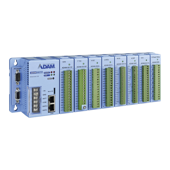
Distributed DA&C System Based on Ethernet
Brand:
Advantech
| Category:
I/O Systems
| Size: 2.99 MB
Table of Contents
Table of Contents
8
Chapter 1 Understanding Your System
15
Introduction
15
Major Features
16
Communication Network
16
Modbus/Tcp Protocol
16
Hardware Capacity & Diagnostic
16
Communicating Isolation
17
Completed Set of I/O Modules for Total Solutions
17
Built-In Real-Time os and Watchdog Timer
17
Software Support
17
Security Setting
18
UDP Data Stream
18
1-2-10 Modbus Ethernet Data Gateway
18
Technical Specification of ADAM-5000/TCP System
19
System
19
Ethernet Communication
19
1-3-3 Serial Communication
19
Power
20
Isolation
20
Mechanical
20
Environment
20
Dimensions
20
Figure 1-2: ADAM-5000/TCP System & I/O Module Dimensions
20
Basic Function Block Diagram
21
LED Status of ADAM-5000/TCP Main Unit
21
Figure 1-3: Function Block Diagram
21
Figure 1-4: ADAM-5000/TCP LED Indicators
21
Chapter 2 Selecting Your Hardware Components
24
Selecting I/O Module
25
Table 2-1: I/O Selection Guidelines
25
Figure 2-1: ADAM-5000 I/O Module Selection Chart
26
Table 2-2: I/O Modules Selection Guide
27
Selecting Power Supply
29
Table 2-3: Power Consumption of ADAM-5000 Series
29
Table2-4: Power Supply Specification Table
30
Selecting Link Terminal and Cable
31
Figure 2-2: Ethernet Terminal and Cable Connection
31
Table 2-5: Ethernet RJ-45 Port Pin Assignment
31
Figure 2-3 RS-485 Terminal and Cable Connection
32
Selecting Operator Interface
33
Chapter 3 Hardware Installation Guide
34
Determining the Proper Environment
35
Check the Content of Shipping Box
35
System Requirement
35
I/O Modules
35
Installing Your Main Unit and Module
36
Figure 3-1: Module Alignment and Installation
36
Figure 3-2: Secure the Module to the System
36
Mounting
37
Panel Mounting
37
DIN Rail Mounting
37
Figure 3-3: ADAM-5000/TCP Panel Mounting Screw Placement
37
Figure 3-4: ADAM-5000/TCP DIN Rail Mounting
38
Figure 3-5: Secure ADAM-5000/TCP System to a DIN Rail
38
Wiring and Connections
39
Power Supply Wiring
39
Figure 3-6: ADAM-5000/TCP Power Wiring
39
I/O Modules Wiring
40
Figure 3-7: ADAM-5000 I/O Module Terminal Block Wiring
40
System Network Connections
41
Figure 3-8: System Network Connection
41
Figure 3-9 Serial Network Connection
42
Assigning Address for I/O Modules
43
Figure 3-10: I/O Modules Address Mapping
43
Table 4-1 I/O Module Support List
45
Chapter 4 I/O Module Introduction
46
Chapter 5 System Hardware Configuration
47
System Hardware Configuration
47
Figure 5-1: Hardware Configuration
47
Install Utility Software on Host PC
48
ADAM-5000/TCP Windows Utility Overview
48
Main Menu
48
Figure 5-2: Operation Screen
48
Ethernet Network Setting
50
Figure 5-4: Network Setting
50
Figure 5-3: Tool Bar
50
Figure 5-5: Communication Testing Function
51
Figure 5-6: Define Device Name and Description
51
Figure 5-7: TCP/IP Network Setting
52
Add Remote Station
53
Figure 5-8: Adding ADAM-5000/TCP Screen
53
I/O Module Canfiguration
54
Figure 5-9: Digital I/O Module Configuration
54
Figure 5-11: Current Analog Input Status
55
Figure 5-10: Operating and Indicating Icons
55
Figure 5-12: Setting Range and Integration Time
56
Figure 5-13: Analog Module Configuration Screen
57
Figure 5-14: Counter/Frequency Module Configuration
57
Figure 5-15: Location of Counter/Frequency Module
58
Figure 5-16: Alarm Setting for Analog Input and Counter Modules
59
I/O Module Calibration
60
Figure 5-17: Zero Calibration
60
Figure 5-18: Span Calibration
60
Figure 5-19: CJC Calibration
61
Figure 5-20: Analog Output Module Calibration
61
Firmware Update
62
Figure 5-21: Firmware Upgrade
62
Security Setting
63
Figure 5-22: Password Setting
63
Terminal Emulation
64
Figure 5-23: Command Emulation
64
5-3-10 Data Stream
65
Figure 5-24: Data Stream Configuration
65
Figure 5-25: Data Stream Monitoring
66
5-3-11 Data Gateway Setting
67
Figure 5-26: RS-485 Modbus Network Setting
67
Chapter 6 Planning Your Application Program
68
Introduction
69
DLL (Dynamic Link Library) Driver
69
Index
69
6-2-2 Programming Flow
71
6-2-3 Function Descriptions
77
Return Codes
97
ADAM-5000/TCP Command
99
Command Structure
99
Figure 6-1: Request Comment Structure
99
Modbus Function Code Introduction
100
Figure 6-2: Response Comment Structure
100
Table 6-1: Response Comment Structure
100
Apply with ASCII Command for ADAM-5000/TCP System
106
Sytax of ASCII
106
Figure 6-3: ASCII Command Structure in ADAM-5000/TCP
106
System Command Set
107
Table 6-2: CPU Command Set Table
107
Table 6-3 Baud Rate Codes
109
Analog Input Command Set
115
Table 6-4: ADAM-5013 RTD Input Command Set Table
116
Table 6-5: ADAM-5017/5018 Analog Input Command Set Table
130
Figure 6-4: Data Format for 8-Bit Parameters
131
Table 6-7 Analog Input Alarm Command Set Table
157
Table 6-8 Analog Input Alarm Command Set Table
176
Analog Output Command Set
196
Table 6-9: Analog Output Command Set Table
196
Digital Input/Output Command Set
210
Table 6-10: Counter/Frequency Command Set Table
220
Appendix A Design Worksheets
300
Table A-1: I/O Data Base
302
Table A-2: Summary Required Modules
304
Table A-3: Table for Programming
305
Appendix B Data Formats and I/O Ranges
308
B.1 Analog Input Formats
309
Analog Input Ranges - ADAM-5017
311
Analog Input Ranges - ADAM-5018/5018P
312
Analog Input Ranges - ADAM-5017H/5017UH
317
B.5 Analog Output Formats
319
B.6 Analog Output Ranges
319
B.7 ADAM-5013 RTD Input Format and Ranges
320
Appendix C Grounding Reference
324
C.1 Grounding
326
Figure C-1: Think the EARTH as GROUND
326
Figure C-2: Grounding Bar
327
Figure C-3: Normal Mode and Common Modc
328
Figure C-4: Normal Mode and Common Modc
329
Figure C-5: the Purpose of High Voltage Transmission
330
Figure C-6: Wire Impedancc
331
Figure C-8: Single Point Grounding (2
333
C.2 Shielding
334
Figure C-9: Single Isolated Cable
334
Figure C-10: Double Isolated Cable
335
Figure C-11: System Shielding
336
Figure C-12: the Characteristic of the Cable
337
Figure C-13: System Shielding (1
338
Figure C-14:System Shielding (2
339
C.3 Noise Reduction Techniques
340
Figure C-15: Noise Reduction Techniques
340
C.4 Check Point List
341
Advertisement
Advertisement
Related Products
Advantech ADAM-5000 Series
Advantech ADAM-5000L/TCP
Advantech ADAM-5069
Advantech ADAM-5056S
Advantech ADAM-5055S
Advantech ADAM-5024
Advantech ADAM-5018P
Advantech ADAM-5053S
Advantech ADAM-5030
Advantech ADAM-5057S
Advantech Categories
Motherboard
Computer Hardware
Desktop
Touch Panel
PCI Card
More Advantech Manuals
Login
Sign In
OR
Sign in with Facebook
Sign in with Google
Upload manual
Upload from disk
Upload from URL