
Related Manuals for Delta 36-475


Summary of Contents for Delta 36-475
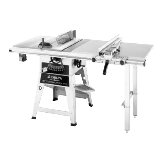
- Page 1 Platinum Edition 10"Contractor s Saw fi with 30" Unifence (Model 36-475) REVISED 6-14-99 PA RT NO. 422-19-651-0042 'Delta International Machinery Corp. 1999...
-
Page 2: Table Of Contents
TA B L E O F C O N T E N T S SAFETY RULES ....................................3 ADDITIONAL SAFETY RULES F O R CIRCULAR S AW S . -
Page 3: Safety Rules
If you have any questions relative to a particular applica- tion, DO N O T use the machine until you have first contacted Delta to determine if it can or should be performed on the product. -
Page 4: Additional Safety Rules For Circular S Aw S
Labor OSHA 1910.213 Regulations. recommended by Delta m a y r e s u l t i n r i s k o f i n j u r i e s . 2 2 . S AV E THESE INSTRUCTIONS. Refer to them fre- 1 3 . -
Page 5: U N Packing A N D Cleaning
U N PACKING A N D CLEANING Carefully unpa c k t h e table saw and all loose items from the shipping containers. Remove the protective coating from the machined surfaces of the saw. This coating may be removed with a soft cloth moistened with kerosene (do not use acetone, gasoline or lacquer thinner for this purpose). - Page 6 1 . Combination Dust Chute/ Support Panel 2 . Motor Pulley 3 . Motor 4 . Pulley Guard 5 . Drive Belt 6 . Spring 7 . Pins (2) for Mounting Motor 8 . Motor Mounting Plate 9 . Lockwashers (4) 1 0 .
-
Page 7: A S S E M B Ly Instructions
A S S E M B LY INSTRUCTIONS ASSEMBLING SAW STA N D 1 . Assemble the dust chute and support panel (A) F i g . 5 , t o t h e i n s i d e o f t h e f r o n t s tand panel (B) with three F i g . -
Page 8: Assembling Saw To St And
ASSEMBLING S AW TO STA N D 1 . F i g . 8 , i l l u s t r a t e s t h e s tand (B) completely assem- b l e d . 2 . Assemble rubber foot (A) Fig. 8, onto the end of each stand leg (B). -
Page 9: Motor
M O TO R The motor shipped with your saw is a 1-1/2 H.P., Ball Bearing, Capa c i t o r St art/Capacitor Run, 115/230 Volt motor. This motor has been specially selected to best supply power to your machine and the relative safety of the machine is enhanced by its use. -
Page 10: Assembling Motor Pulley,B E L T And Pulley Guard, And Drive Belt
ASSEMBLING M O TO R PULLEY, BELT A N D PULLEY GUARD, A N D DRIVE BE LT W ARNING: W H E N ASSEMBLING M O TO R PULLEY, BELT A N D PULLEY GUARD, A N D DRIVE BELT, MAKE C E R TAIN T H E M O TO R I S D I S C O N N E C T E D F R O M THE P O W E R SOURCE. -
Page 11: Connecting Motor Cord To Switch Assembly
7 . L i ft the motor and assemble the drive belt (H) Fig. 20, to the arbor pulley and motor pulley (B). The weight of the motor will provide the correct belt tension. Fig. 20 8 . W ARNING: IMMEDIATELY AFTER ASSEMBLING THE BELT, RAISE THE S AW B L A D E TO ITS M A X I M U M HEIGHT A N D TILT THE S AW BLADE TO 45 DEGREES. -
Page 12: Assembling Blade Guard And Sp L I T T E R Assembly
2 . Fig. 24, illustrates the motor cord connected to the switch assembly. Fig. 24 ASSEMBLING B L A D E GUARD A N D SPLITTER A S S E M B LY W ARNING: M A K E C E R TAIN T H E S AW I S DISCON- NECTED F R O M THE P O W E R S O U R C E. - Page 13 5 . If an alignment is necessary, loosen the two screws ( F ) Fig. 28, align bracket (D) with the arbor flange (E) and tighten screws (F). 6. Loosely assemble large washer and screw (C) F i g . 2 8 , t o t h e i n s i d e s p l i t t e r b r a c k e t .
- Page 14 9 . W ith the blade guard (L) Fig. 32, in the raised posi- tion, assemble the saw blade (K) on the saw arbor with two arbor wrenches supplied. Fig. 32 1 0 . Using a straight edge, check to see if the saw blade is aligned with the rear of the splitter (G), as shown in Figs.
-
Page 15: Assembling Extension Wing
ASSEMBLING EXTENSION WING 1 . Assemble extension wing (A) Fig. 36, to the saw t able using three 7/16-20 x 1-1/4† screws (B) and lock- washers (C) as shown in Fig. 37. Fig. 36 2 . W ith a straight edge (D) Fig. 36, make certain the extension wing (A) is level with the saw table before tightening three screws (B) F i g . -
Page 16: Assembling Table Mounting Brackets To Saw Table
ASSEMBLING TABLE MOUNTING BRACKETS TO S AW TABLE 1 . Assemble Z-brackets ( A ) F i g . 4 0 , t o t h e t h r e e tapped holes at the inside edge on the right side of saw ta b l e ( B ) , using three 7/16-20 x 3/4†hex head screws (C) with flat washers and lockwashers. -
Page 17: Assembling Table Legs And Front Table Support
ASSEMBLING TA B L E L E G S AND FRONT TABLE SUPPORT Fig.45 1 . The table board supplied will require thirteen 1/8† diameter x 3/8†deep holes to be drilled in the bottom of t h e table board at the locations illustrated in Fig. 45. 2 . - Page 18 4 . Insert foot adapter (T) Fig. 48, into the bottom of each leg (A). Assemble the 3/8† jam nut (V) Fig. 48, approximately 3/4 of the way onto leveling screw (W) and place a flat washer (X) on the level- ing screw.
-
Page 19: Assembling Unifence Table To Saw
ASSEMBLING UNIFENCE TA B L E TO S AW 1 . P o s i t i o n table board (A) Fig. 51, onto angle brackets ( B ) . Fig. 51 2 . While holding table board firmly against the saw t a b l e , f a s t e n table to three angle brackets ( B ) F i g . -
Page 20: Assembling Unifence Guide Rail
ASSEMBLING UNIFENCE GUIDE RAIL 1 . Locate the cardboard template (A) Fig. 56, from the packing material of the Unifence. 2 . Place two 3/8† -24 hex nuts, one of which is shown at ( B ) F i g . 5 6 , i n p o s i t i o n o n t h e t w o tabs of the template (A). 3 . -
Page 21: Assembling Cursor To Unifence Body
7 . Move the square (H) Fig. 60, to the end of the Unifence table and check to make certain the same dis- t ance is kept from the top surface of the extension table (K) to the top surface of the guide rail (C). Move the front t able support (L) Fig. -
Page 22: Assembling Unifence Body To Guide Rail
ASSEMBLING UNIFENCE B O D Y TO GUIDE RAIL 1 . Turn fence body (A) Fig. 65, upside down and lay it o n a table or bench. Push handle (B) in against fence body. Make certain the surface (C) of clamp bracket is parallel to the face (D) of the fence body, and that the inside edge (E) of the clamp bracket is pa r a l l e l t o s u r f a c e ( F ) of the fence body. -
Page 23: Assembling Fence To Unifence Body
ASSEMBLING UNIFENCE TO UNIFENCE B O D Y 1 . The fence (A) can be assembled to clamp plate (B) Fig. 69 in either the horizontal position as shown in Fig. 69, or the vertical position as shown in Fig. 70. Make certain the two lock knobs (C), are loose and slide fence (A) onto clamp plate (B) as shown. -
Page 24: Extension Cords
EXTENSION C O R D S TO TA L LENGTH O F G A G E O F EXTENSION C O R D IN FEET C O R D TO U S E Use proper extension cords. Make sure your extension cord is in good condition and is a 3-wire extension cord 120 VOLT 240 VOLT... -
Page 25: 240 Volt, Single Phase Operation
240 volts and the rated current of the saw as illustrated to an outlet having the same configuration as the plug in Fig. 75. Conta c t y o u r l o c a l Authorized Delta Service illustrated in Fig. 75. No adapter is available or should be Center or qualified electrician for proper procedures to used with the 240 Vo l t p l u g . -
Page 26: Overload Protection
OVERLOAD PROTECTION The motor recommended for use with your saw is equipped with a reset overload relay button (A) F i g . 7 9 . I f the motor shuts o ff o r f a i l s t o s tart due to overloading (cutting stock too fast, using a dull blade, using the saw beyond its capa c i t y, e t c . -
Page 27: Backlash Adjustments For Blade Raising And Blade Tilting Mechanisms
B A C K L A S H ADJUSTMENTS F O R B L A D E RAISING A N D BLADE TILTING MECHANISMS A fter a period of extended use, if any play is detected in the blade raising or blade tilting mechanisms, the follow- ing adjustments should be made. -
Page 28: Adjusting Table Insert
ADJUSTING TA B L E INSERT M A K E C E R TAIN T H E MACHINE I S DISCONNECTED F R O M THE P O W E R SOURCE. Place a straight edge across the table at both ends of the t able insert as shown in F i g . -
Page 29: Storing The Miter Gage, Rip Fence, And Arbor Wrenches
STORING TH E MITER GAGE, RIP FENCE, AND A R B O R W R E N C H E S 1 . When not in use, the miter gage (A) Fig. 90, can be stored through the hole located at the front side of the s tand as shown. -
Page 30: Adjusting Fence Parallel To Miter Gage Slots
4 . To move the fence along the guide rail, simply lift u p clamp lever (A), as shown in Fig. 94, slide fence to desired position on the rail, and push down on clamp lever (A) to lock fence in place. Fig. -
Page 31: Adjusting Fence 90 Degrees To Table
ADJUSTING FENCE 90 DEGREES TO TA B L E The fence must be adjusted so that the face of fence (A) Fig. 98, is 90 degrees to the ta b l e . To check if the fence is 90 degrees to the table, place a square (B) on the table with one end of the square against the fence, as shown. -
Page 32: O P E R Ations
O P E R ATIONS Common sawing operations include ripping and cross-cutting plus a few other standard operations of a fundamenta l n a t u r e . As with all power tools, there is a certain amount of hazard involved with the operation and use of the tool. Using the tool with the respect and caution demanded as far as safety precautions are concerned, will considerably lessen the possibility of personal injury. -
Page 33: Using The Fence As A Cut-Off Gage
. The saw blade guard must be used. On Delta saws, the guard has anti-kickback fingers to prevent kickback and a split- ter to prevent the saw kerf from closing and binding the blade. -
Page 34: Ripping On Left Side Of Saw Blade
Fig. 108 Fig. 109 If the ripped work is less than 4 inches wide, a push stick should always be used to complete the feed, as shown i n F i g . 1 0 8 . The push stick can easily be made from scrap material as explained in the section C O N- STRUCTING PUSH STICK. -
Page 35: Using Accessory Moulding Cutterhead
USING A C C E S S O RY MOULDING CUTTERHEAD Moulding is cutting a shape on the edge or face of the work. Cutting mouldings with a moulding cutterhead in the circular saw is a fast, safe and clean operation.The many different knife shapes available make it possible for the operator to produce almost any kind of mouldings, such as various styles of corner moulds, picture frames,... -
Page 36: Using Accessory Dado Head
It is necessary when using the moulding cutterhead to add wood-facing (C) to the face of the rip fence, as shown in Fig. 11 7 . The wood-facing is attached to the fence with wood screws through holes which must be drilled in the fence. -
Page 37: Using Auxiliary Wood Facing On The Rip Fence
The dado head set (D) Fig. 121, is assembled to the saw arbor as shown. IMPORTA N T:The blade guard and splitter assembly cannot be used when dadoing and must be removed or swung to the rear of the saw as explained previously in this manual. -
Page 38: Constructing A Push Stick
CONSTRUCTING A PUSH STICK When ripping work less than 4 inches wide, a push stick should be used to complete the feed and could easily be made from scrap material by following the pattern shown in Fig. 124. -
Page 39: Parts, Service Or Wa R R A N T Y Assista N C E
Delta s t o l l - f r e e service stations listed in your owner s manual. To h o t l i n e number. -
Page 40: W A R R A N T Y
Delta Machinery D e l ta w i l l r e pa i r o r r e p l a c e , a t i ts expense and at its option, any Delta machine, machine part, or machine...
Need help?
Do you have a question about the 36-475 and is the answer not in the manual?
Questions and answers