Table of Contents
Advertisement
Available languages
Available languages
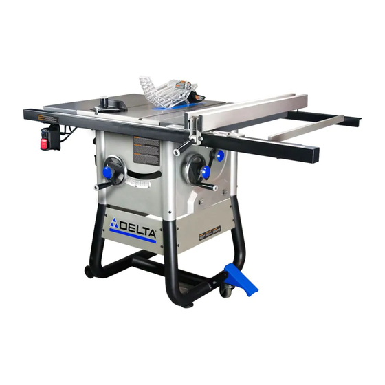
10-Inch contractor table Saw
Scie de table de 10 pouces
(254 mm) pour entrepreneurs
Sierra de mesa de 10 pulgadas
(254 mm) para contratista
Français (32)
Español (63)
www.DeltaMachinery.com
Instruction Manual
Manuel d'utilisation
Manual de instrucciones
INSTRUCTIVO DE OPERACIÓN, CENTROS
DE SERVICIO Y PÓLIZA DE GARANTÍA.
LÉASE ESTE INSTRUCTIVO
ANTES DE USAR EL PRODUCTO.
To reduce risk of serious injury, thoroughly read and comply with all warnings and instructions in
this manual and on product.
KEEP THIS MANUAL NEAR YOUR SAW FOR EASY REFERENCE AND TO INSTRUCT OTHERS
36-725
Advertisement
Table of Contents

Related Manuals for Delta 36-725


Summary of Contents for Delta 36-725
- Page 1 Manuel d’utilisation Manual de instrucciones INSTRUCTIVO DE OPERACIÓN, CENTROS DE SERVICIO Y PÓLIZA DE GARANTÍA. 36-725 LÉASE ESTE INSTRUCTIVO ANTES DE USAR EL PRODUCTO. To reduce risk of serious injury, thoroughly read and comply with all warnings and instructions in this manual and on product.
-
Page 2: Table Of Contents
Checking Fence Alignment ..........19 SPANISH ................... 65 FUNCTIONAL DESCRIPTION ® The DELTA #36-725 10-inch Contractor Table Saw is SPECIFICATIONS designed for portability and high quality performance. It includes: basic machine, sturdy tubular steel stand, ® integral dust chute, a T-Square... -
Page 3: Important Safety Instructions
If you have any questions or concerns relative to the use of your tool or the contents of this manual, stop using the tool and contact DELTA ® Power Equipment Corporation Customer Care at 1-800-223-7278. -
Page 4: Save These Instructions
GENERAL POWER TOOL SAFETY RULES 18. USE RECOMMENDED ACCESSORIES. Consult 24. SERVICE PARTS. Use only identical replacement manual for recommended accessories. Use of parts when servicing your tool. inappropriate accessories may cause personal 25. WEAR PROPER APPAREL. Do not wear loose injury or property damage. -
Page 5: Table Saw Safety Rules
TABLE SAW SAFETY RULES Failure to follow these rules may result in serious personal injury. • SEE GENERAL POWER TOOL SAFETY SECTION OF THIS MANUAL. Read entire instruction manual before operating saw. Learning the saw's proper applications, limitations, and specific potential hazards will greatly minimize the possibility of accidents and injury. -
Page 6: Making A Push Stick
TABLE SAW SAFETY RULES (continued) 15. AVOID AWKWARD OPERATIONS AND HAND 21. BEFORE LEAVING THE SAW , wait for the blade to POSITIONS where a sudden slip could cause a come to a complete stop, then disconnect from the hand to move into a saw blade. Operate with table power source, clean the table and work area, and at or near waist level for maximum balance and lock out switch to prevent unauthorized use. -
Page 7: Power Connections
TABLE SAW SAFETY RULES (continued) KICKBACKS Kickbacks can cause serious injury. A kickback occurs the nearest authorized service center for repair. when a part of the workpiece binds between the saw • Plastic and composite materials (like hardboard) may blade and the rip fence, or other fixed object, and be cut on your saw. -
Page 8: Extension Cords
POWER CONNECTIONS (continued) Check with a qualified electrician or service personnel 3-conductor receptacles that accept the machine’s if the grounding instructions are not completely plug, as shown in Figure A, or a properly grounded understood, or if in doubt as to whether the machine is receptacle with a grounding means adaptor, as shown properly grounded. -
Page 9: Unpacking
• Prior to tool assembly and use, read this manual any parts are missing, damaged or preassembled, do thoroughly to familiarize yourself with proper ® not assemble. Instead, call DELTA Customer Care at assembly, maintenance and safety procedures. 1-800-223-7278 for assistance. -
Page 10: Hardware Package
UNPACKING (continued) HARDWARE PACKAGE 11. 1/4"-20 x 1/2" hex button head screw with 1/4" spring washer (7) 12. Front rail union plate(1) DESCRIPTION (QTY) 13. M5 x16mm shoulder bolt (2) 1. M8 x 70mm carriage bolt (1) 14. M5 nylock nut (2) 2. -
Page 11: Fixed Wheels And Stationary Feet
ASSEMBLY (continued) FIXED WHEELS AND STATIONARY FEET 1. Attach the two fixed wheels (A) to the two left leg, opposite the pivot caster, using the carriage shoulder bolt as in Figure 2. 2. Screw the adjustable feet (C) into the threaded inserts in the right leg, next to the pivot caster. -
Page 12: Front And Rear Rails
ASSEMBLY (continued) FRONT AND REAR RAILS 1. Attach the front rail halves (2” X 2” angles 36 ¾” and 20” long) to the table front and extension wings. Align the holes (A) in the front of the table top with the holes (B) in the left (short) and right (long) sections of the front rail, as shown in Figure 5, and attach using four 5/16-18 x 1 1/8-inch flat... -
Page 13: Throat Plate
ASSEMBLY (continued) THROAT PLATE 1. To install throat plate, lower blade below tabletop, then carefully feed the throat plate, slotted end first, from the front of the table to the rear, keeping the blade centered within the slot on the throat plate. -
Page 14: Blade Guard
RIP FENCE ON-BOARD STORAGE Attach the handle to the fence cam The Delta #36-725 contractor table saw comes with on-board storage for the provided miter gauge, arbor The rip fence slides onto the rear fence rail so that the wrench, push stick and fence. There is also on-board hook is under the rear rail and rides on the front guide storage for spare saw blades (sold separately). -
Page 15: Adjusting The 90° And 45° Positive Bevel Stops
ASSEMBLY (continued) ADJUSTING 90° AND 45° POSITIVE BEVEL STOPS There are positive stops at each end of the bevel 5. Rotate the blade tilt wheel counterclockwise until range. To ensure accurate cuts, the positive stops it rests on the 45° stop. Then repeat Steps 4 and must be positioned at exactly at 90°... -
Page 16: Preparing To Cut
PREPARING TO CUT ASSEMBLY (continued) RAISING AND LOWERING THE BLADE For most applications, it is recommended that you raise the blade 1/8-inch (3.2mm) to 1/4-inch (6.4mm) above the top surface of the workpiece. Raise or lower the blade with the hand wheel (A) located on the front of the saw (See Figure 12). -
Page 17: Selecting And Storing Saw Blades
PREPARING TO CUT ASSEMBLY (continued) SELECTING AND STORING SAW BLADES Riving knives must be matched to saw blade Use only saw blades designed for maximum safe dimensions in order to function effectively. operating speeds of 3,600 RPM or greater. The saw blade furnished with your new saw is a Saw blades should always be kept sharp. -
Page 18: Height Settings
PREPARING TO CUT (continued) RIVING KNIFE HEIGHT 1. Release lever and pull on riving knife to make sure it is properly seated in the raised or lowered position. SETTINGS 2. Securely clamp riving knife by pushing riving knife clamping lever back down to the horizontal The height of the riving knife should be adjusted based position. -
Page 19: Using The Miter Gauge
PREPARING TO CUT (continued) USING THE MITER GAUGE The miter gauge is equipped with adjustable index stops at 90°, 75°, 60°, 45° and 30°. To set the miter for an angled cut, see Figure 18 and: 1. Loosen the handle (A). 2. -
Page 20: Operation
2. The use of attachments and accessories not recommended by DELTA® Power Equipment Corporation may result in injury. STARTING AND STOPPING THE SAW The POWER switch (Figure 20) is located underneath the front left extension wing. -
Page 21: Overload Protection
OPERATION (continued) OVERLOAD PROTECTION Your saw is supplied with overload protection. If the reset button (B), on the motor under the saw, shown in motor shuts off or fails to start due to overloading Figure 20, and restart the saw. (cutting stock too fast, using a dull blade, using the NOTICE: If the motor continually shuts off due to saw beyond its capacity, etc.) or low voltage, let the... -
Page 22: Rip Cuts
OPERATION (continued) RIP CUTS 12. Use the push stick and any other cutting aids, as needed, to hold the workpiece against the table and fence, and push the workpiece past the 1. Remove miter gauge blade. A push stick is included with this saw, and 2. -
Page 23: Cross-Cuts
OPERATION (continued) CROSSCUTTING face, For instructions about making auxiliary faces, see Cutting Aids section on page 26 of this manual. 7. Make sure the workpiece is clear of the blade - at least 1 inch or 25mm away - before starting the saw. •... -
Page 24: Compound Miter Cuts
OPERATION (continued) COMPOUND MITER CUTS This is a combination of bevel crosscutting and mitering. Refer to Figure 25 and follow the instructions for both bevel crosscutting and mitering. Remember to use the right miter slot for all bevel cuts. LARGE PANEL CUTS Place workpiece supports at the same height as the saw table behind saw to support the cut workpiece, and alongside (s) of saw, as needed. -
Page 25: Dado Cuts
OPERATION (continued) MAKING A DADO CUT Dado blades are stacked blades that can be used when making non-through cuts including through cut slots. Dado blades require a special throat plate. Dado blades and throat plates are all sold separately. • Carefully follow the instructions accompanying the dado blade for proper installation, set up and operation. -
Page 26: Push Blocks
CUTTING AIDS AND ACCESSORIES (continued) AUXILIARY RIP FENCE FACING Use an auxiliary rip fence facing when needed for special cuts, such as ripping material that is thin enough to slide under the rip fence provided with your saw, or when a taller rip fence is necessary to complete your cut. -
Page 27: Featherboards
CUTTING AIDS AND ACCESSORIES (continued) FEATHERBOARD Select a solid piece of lumber approximately Featherboards are used to keep the work in contact with the fence and table (Figure 32), and help prevent ¾-inch thick, 2 ½-inches wide and 12-inches long. kickback. -
Page 28: Alignment
ALIGNMENT RIVING KNIFE ALIGNMENT 18). Then verify that the riving knife is perpendicular to table and in-line with the blade face. WITH THE BLADE 11. If needed, use the set screws (D) to align the riving knife with blade face and the square. Alignment between the riving knife and blade is set at the factory and, in most cases, will not need to 12. -
Page 29: Aligning Fence Parallel To Miter Slot
ALIGNMENT (continued) ALIGNING FENCE PARALLEL TO ALIGNING FENCE MITER SLOT PERPENDICULAR TO THE TABLE 1. Move fence adjacent to right miter gauge and secure to the guide tube by lowering the fence 1. Move fence over the cast iron table and secure clamping lever. -
Page 30: Volt Single Phase Operation
120 volt operation. It can be converted for 240 volt operation. For conversion from 120 volt to 240 volt, please call ahead to DELTA Customer Care at 1-800-223-7278. Use the following instructions to convert your saw to 240 volts... -
Page 31: Maintenance
Since accessories other than those offered by DELTA have not been tested with this product, ® use of such accessories could be hazardous. For safest operation, only DELTA recommended ® accessories should be used with this product. -
Page 32: Warranty
Five Year Limited New Product Warranty DELTA will repair or replace, at its expense and at its option, any new DELTA machine, machine part, or machine accessory which in normal use has proven to be defective in workmanship or material, provided that the customer returns the product prepaid to a DELTA factory service center or authorized service station with proof of purchase of the product within five years and provides DELTA with reasonable opportunity to verify the alleged defect by inspection. -
Page 33: French
Si tiene cualquier duda o inquietud en relación al uso de su herramienta o al contenido de este manual, detenga el uso ® de la herramienta y comuníquese con atención al cliente de DELTA Power Equipment Corporation al 1-800-223-7278. LOGOTIPOS DE SEGURIDAD Las siguientes definiciones describen el nivel de gravedad de cada palabra de alarma. - Page 34 REGLAS GENERALES DE SEGURIDAD PARA HERRAMIENTAS ELéCTRICAS atmósferas gaseosas o explosivas. Los motores e antes de conectar el cable de la herramienta. interruptores de estas herramientas pueden crear 17. No toque las puntas de metal del enchufe chispas y encender los gases. cuando desconecte o conecte el cable.
- Page 35 REGLAS GENERALES DE SEGURIDAD PARA HERRAMIENTAS ELéCTRICAS 27. PROTECCIÓN DE OÍDOS. Todas las personas en lejos del rostro y el cuerpo. Siempre opere la herramienta en un área con buena ventilación y el área de trabajo deben usar protección de oídos adecuada consistente con los niveles y exposición proporcione una eliminación de polvo adecuada.
- Page 36 REGLAS DE SEGURIDAD DE LA SIERRA DE MESA No seguir estas reglas puede provocar graves lesiones personales. • CONSULTE LA SECCIÓN DE SEGURIDAD GENERAL PARA HERRAMIENTAS ELéCTRICAS EN ESTE MANUAL. Lea todo el manual de instrucciones antes de operar la sierra. Conocer las aplicaciones adecuadas, limitaciones y riesgos potenciales específicos de la sierra minimizará...
- Page 37 REGLAS DE SEGURIDAD DE LA SIERRA DE MESA (continuación) usar, inspeccione la hoja para comprobar que no 20. NUNCA REALICE TRABAJOS DE DISEÑO, tenga grietas ni dientes rotos. No use una hoja ENSAMBLE O PREPARACIÓN SOBRE LA MESA dañada o sin filo. Siempre use la hoja dentro del O ÁREA DE TRABAJO cuando la sierra esté...
- Page 38 REGLAS DE SEGURIDAD DE LA SIERRA DE MESA (continuación) CONTRAGOLPES la máquina al centro de servicio autorizado más cercano para su reparación. Los contragolpes pueden ocasionar lesiones graves. • Los materiales de plástico y compuestos (como Un contragolpe ocurre cuando una parte de la pieza madera prensada) pueden cortarse en la sierra.
- Page 39 CONEXIONES A LA FUENTE DE PODER (continuación) Verifique con un electricista calificado o personal de debidamente conectados a tierra que puedan servicio si las instrucciones de conexión a tierra no se conectar el enchufe de la máquina, como se muestra entienden por completo o si tiene dudas acerca de si en la Figura A, o un tomacorriente debidamente la máquina está...
- Page 40 Si falta alguna pieza, o está con atención este manual para familiarizarse con dañada o preensamblada, no ensamble la sierra. En los procedimientos adecuados de ensamblado, lugar de ello, llame al servicio al cliente de DELTA ® mantenimiento y seguridad. 1-800-223-7278 para solicitar ayuda.
- Page 41 DESEMPAQUE (continuación) PAQUETE DE TORNILLERÍA 11. Tor nillo de botón de cabeza hexagonal de 1/4"-20 x 1/2" con arandela de resorte 1/4" (7) 12. Placa de unión del riel frontal (1) DESCRIPCIÓN (CANTIDAD) 13. Perno de tope M5 x 18 mm (2) 1.
- Page 42 ENSAMBLE (continuación) RUEDAS FIJAS Y PATAS ESTACIONARIAS 1. Sujete las dos ruedas fijas (A) a las dos patas izquierdas, al lado opuesto de la rueda pivotante, usando el perno de cabeza redonda de tope como en la Figura 2. 2. Atornille las patas ajustables (C) en los insertos roscados de la pata derecha, junto a la rueda pivotante.
- Page 43 ENSAMBLE (continuación) RIELES FRONTALES Y POSTERIORES 1. Sujete las mitades del riel frontal (ángulos de 2" X 2" de 36 ¾” y 20” de largo) al frente de la mesa y las alas de extensión. Alinee los orificios (A) en el frente de la parte superior de la mesa con los orificios (B) en la sección izquierda (corta) y derecha (larga) del riel frontal, como se muestra en la...
- Page 44 ENSAMBLE (continuación) PLACA DE GARGANTA 1. Para instalar la placa de garganta, baje la hoja hasta abajo de la parte superior de la mesa, luego con cuidado deslice la placa de garganta, primero el extremo ranurado, desde la parte frontal de la mesa hasta la parte posterior, manteniendo la hoja centrada dentro de la ranura en la placa de garganta.
- Page 45 TOPE GUÍA PARA CORTE ALMACENAMIENTO INCLUIDO AL HILO La sierra de mesa para contratista Delta #36-725 incluye un almacenamiento para la galga de inglete, Sujete la agarradera a la leva de la guía llave de eje, empujador y tope guía proporcionados.
- Page 46 ENSAMBLE (continuación) AJUSTE DE LOS TOPES BISELADOS POSITIVOS DE 90° Y 45° Hay topes positivos en cada extremo del rango de que la hoja esté a 90 grados cuando se regresa a biselado. Para garantizar cortes exactos, los topes la posición de tope. positivos deben colocarse exactamente a 90°...
- Page 47 PREPARACIÓN PARA CORTES ENSAMBLE (continuación) ELEVACIÓN Y DESCENSO DE LA HOJA En la mayoría de las aplicaciones, se recomienda que eleve la hoja 1/8 pulg. (3.2 mm) a 1/4 pulg. (6.4 mm) por encima de la superficie superior de la pieza de trabajo. Suba o baje la hoja con la rueda manual (A) situada en la parte frontal de la sierra (consulte la Figura 12).
- Page 48 PREPARACIÓN PARA CORTES ENSAMBLE (continuación) SELECCIÓN Y ALMACENAMIENTO DE LAS HOJAS DE SIERRA Los separadores deben coincidir con las dimensiones Use solo hojas de sierra diseñadas para las máximas de la hoja de sierra para poder funcionar eficazmente. velocidades de operación segura de 3,600 RPM o más. La hoja de sierra proporcionada con la sierra nueva Las hojas de sierra siempre deben mantenerse es una hoja de combinación de 10 pulgadas (254 mm)
- Page 49 PREPARACIÓN PARA CORTES (continuación) AJUSTES DE ALTURA 1. Suelte la palanca y jale del separador para asegurarse de que está correctamente colocado DEL SEPARADOR en la posición elevada o descendente. La altura del separador debe ajustarse en base al tipo 2.
- Page 50 PREPARACIÓN PARA CORTES (continuación) USO DE LA GALGA DE INGLETE La galga de inglete está equipada con topes divisores ajustables a 90°, 75°, 60°, 45° y 30°. Para preparar el inglete para un corte en ángulo, consulte la Figura 18 y: 1.
- Page 51 • ¿Es necesario tener auxiliares de corte? Si es así, ¿están instalados o al alcance para su uso correcto? 2. El uso de aditamentos y accesorios no recomendados por DELTA® Power Equipment Corporation pudiera resultar en lesiones. ARRANQUE Y PARO DE LA SIERRA El interruptor POWER (encendido) (Figura 20) se encuentra abajo del ala de extensión izquierda frontal.
- Page 52 FUNCIONAMIENTO (continuación) el botón rojo de restablecimiento (B) en el motor PROTECCIÓN CONTRA debajo de la sierra, que se muestra en la Figura 20 y SOBRECARGAS vuelva a encender la sierra. AVISO: Si el motor se apaga continuamente debido La sierra se proporciona con protección contra a una sobrecarga, comuníquese con un electricista sobrecargas.
-
Page 53: Cortes Al Hilo
FUNCIONAMIENTO (continuación) CORTES AL HILO 12. Use el empujador y cualquier otro auxiliar de corte, según sea necesario, para sujetar la pieza de trabajo contra la mesa y la guía, y empuje la 1. Retire la galga de inglete pieza de trabajo hasta que pase por la hoja. Un 2. -
Page 54: Corte Transversal
FUNCIONAMIENTO (continuación) CORTE TRANSVERSAL a la galga de inglete y sujete la pieza de trabajo a la parte frontal del auxiliar, para instrucciones sobre cómo hacer auxiliares, consulte la sección auxiliares de corte en la página 89 de este manual. •... - Page 55 FUNCIONAMIENTO (continuación) CORTES DE INGLETE COMPUESTOS Este es una combinación de corte transversal biselado e ingletes. Consulte la Figura 25 y siga las instrucciones para corte transversal biselado e ingletes. Recuerde usar la ranura de inglete derecho para todos los cortes biselados. CORTES DE PANEL LARGOS Coloque los soportes de la pieza de trabajo a la misma altura que la mesa de sierra atrás de la sierra para...
- Page 56 FUNCIONAMIENTO (continuación) REALIZAR UN CORTE DE RANURA Las hojas para ranurar son hojas apiladas que pueden usarse para realizar cortes sin traspaso incluyendo ranuras de corte completo. Las hojas para ranurar requieren de una placa de garganta especial. Las hojas para ranurar y las placas de garganta se venden por separado.
- Page 57 AUXILIARES Y ACCESORIOS DE CORTE (continuación) REFRENTADO DEL TOPE GUÍA PARA CORTE AL HILO AUXILIAR Use un refrentado del tope guía para corte al hilo auxiliar cuando sea necesario para cortes especiales, tales como material de corte al hilo que es suficientemente delgado para deslizarse por debajo del tope guía proporcionado con la sierra o cuando se necesita un tope guía más alto para terminar el...
- Page 58 AUXILIARES Y ACCESORIOS DE CORTE (continuación) TABLAS DE CUÑA Seleccione un trozo sólido de madera de Las tablas de cuña se usan para mantener el trabajo aproximadamente ¾ de pulgada de grosor, 2 ½ en contacto con la guía y la mesa (Figura 32) y ayudan a prevenir los contragolpes.
- Page 59 ALINEACIÓN ALINEACIÓN DEL SEPARADOR el separador esté perpendicular a la mesa y en línea con la parte frontal de la hoja. CON LA HOJA 11. De ser necesario, use los tornillos de fijación (D) para alinear el separador con la parte frontal de la La alineación entre el separador y la hoja se fija hoja y la escuadra.
- Page 60 ALINEACIÓN (continuación) ALINEACIÓN PARALELA DE ALINEACIÓN PERPENDICULAR LA GUÍA CON LA RANURA DE LA GUÍA CON LA MESA DEL INGLETE 1. Mueva la guía sobre la mesa de hierro fundido y asegúrela al tubo de guía bajando la palanca de 1.
- Page 61 120 voltios. Puede convertirse para operar a 240 voltios. Para la conversión de 120 a 240 voltios, por favor llame con anticipación a Servicio al Cliente de DELTA al 1-800- 223-7278. Use las siguientes instrucciones para convertir la sierra a 240 voltios.
- Page 62 Para solicitar ayuda con su máquina, visite nuestro sitio web en para obtener www.DeltaMachinery.com ® una lista de los centros de servicio o llame a atención al cliente de DELTA Power Equipment al 1-800-223-7278. LA SIERRA NO ARRANCA Si su máquina no arranca, verifique que las puntas del enchufe tengan un buen contacto con el tomacorriente y verifique el botón de restablecimiento en el alojamiento del interruptor de alimentación.
- Page 63 DELTA o a una estación de servicio autorizada con el comprobante de compra del producto en un plazo de cinco años y le proporcione a DELTA la oportunidad razonable...
- Page 64 1924 Pearman Dairy Rd., Anderson, SC 29625 1-800-223-7278 www.DeltaMachinery.com Copyright © 2013 DELTA Power Equipment Corporation DPEC002778 - 9/25/2013 ®...
Need help?
Do you have a question about the 36-725 and is the answer not in the manual?
Questions and answers